Note: Descriptions are shown in the official language in which they were submitted.
File number. 12807-025
Title of the Invention
Replaceable thread insert with external friction surface and method
Cross-Reference to Related Applications
[0001] The present patent application claims the benefits of priority of
United States
Provisional Patent Application No. 62/703,277, entitled "REPLACEABLE THREAD
INSERTS WITH EXTERNAL FRICTION SURFACE AND METHOD", and filed at the
United States Patent and Trademark Office on July 25, 2018.
Field of the Invention
[0002] The present invention generally relates to attachment of wood cutting
apparatus.
Particularly, the present invention relates to attachment of wood cutting
knife, knife
holder, knife assembly and method of using the same.
Background of the Invention
[0003] The knife assembly are held by a bolt. The bolt is screwed into threads
in the
chipping head or chipping assembly. The bolt, for this type of application, is
screwed
with a high initial torque. Due to the nature of the mounting and use, the
replacement of
the bolts is required periodically. The threads in the chipping head work pair
with the
bolt. The use of existing thread inserts (threads on the inside diameter and
threads on the
outside diameter) requires regular maintenance and the existing thread inserts
need to be
replaced or repaired periodically. Eventually this maintenance will damage the
threads in
the chipping head.
Summary of the Invention
[0004] As opposed to the existing method of replaceable thread insert, threads
on the
inside diameter (ID) and threads on the outside diameter (OD), the invention
does not
require any threads on the outside surface.
[0005] The outer section of the replaceable thread inserts 60 with external
friction surface
consists of one or more inclined or tapered planes. The inner section of the
part can be
threaded or designed to receive a stud or any kind of nut that would allow the
replaceable
thread inserts 60 to be maintained in place with the use of a bolt 50 or a nut
70.
- 1 -
CA 3050585 2019-07-25
File number 12807-025
[0006] The knife assembly and method according to the present invention aims
at
facilitating the manufacturing of the chipping head.
[0007] Also, in relationship to the maintenance, this invention allows to
replace worn or
damaged threads without having to machine the chipping head.
[0008] One or more inclined or tapered planes allow to hold the replaceable
threads with
no other hardware or assembly.
[0009] Friction in relation to the surfaces in contact on the exterior walls
of the
replaceable thread inserts 60 ensures its good maintenance while allowing a
simple
dismantling without damage.
[0010] Given the limited access to the rear of the assembly, the replaceable
thread inserts
60 in connection with this invention does not require mechanical assembly
involving a
retaining part or a bolt. Only friction ensures its solid and faithful
holding.
[0011] Some of the advantages of a replaceable thread inserts comprise having
treaded
surface that is strong enough to be mounted and/or dismounted from a chipping
assembly, ease the manufacturing as the thread inserts dimensions have a
higher tolerance
to errors, the metal, typically steel, used to make the inserts and the
chipping assembly
may be different, the force applied by the bolt against the frustoconical
inserts
strengthens the assembly instead of collapsing and the area of the external
surface of the
inserts is greater than the area of the internal threaded surface.
[0012] In one aspect of the invention, a replaceable threaded insert for
mounting a tool to
a chipping assembly is provided. The replaceable threaded insert comprises a
first
extremity defining a first area, the first extremity comprising a passage
adapted to receive
a body portion of a bolt, a second extremity defining a second area, the
second area being
greater than the first area and an external tapered surface delimited by the
first and second
extremities, the external slanted surface being adapted to be pressed against
an internal
surface of an aperture of the chipping assembly.
[0013] The passage of the replaceable threaded insert may be threaded and the
body
portion may be screwed into the threaded passage of the replaceable threaded
insert. The
bolt may extend from the passage of the replaceable threaded and being mounted
with a
- 2 -
CA 3050585 2019-07-25
File number 12807-025
nut. A threaded bolt may extend from the first extremity of the threaded
insert and may
be adapted to slide in an aperture of the tool.
[0014] The angle of the tapered opening of the chipping head being between
0.01 and 15
degrees and the internal surface of the aperture of the chipping head may be
tapered. The
angle of the tapered opening of the chipping head may be about equal to the
angle of the
external tapered surface of the replaceable thread insert.
[0015] The tool may be a knife holder and the chipping assembly may be a
chipping
head.
[0016] In another aspect of the invention, a method for removably mounting a
tool to a
chipping assembly is provided. The method comprises sliding a tapered insert
in an
opening of the chipping assembly, positioning a bolt in an opening of the tool
aligned
with the opening of the chipping assembly and pressing the tapered insert in
the opening
of the chipping assembly by tightening the bolt to contact the tool against
the chipping
assembly.
[0017] The pressing of the tapered insert in the opening of the chipping
assembly may
removably hold the tapered insert in the opening of the chipping assembly. The
pressing
of the tapered insert in the opening may create friction between an internal
surface of the
opening of the chipping assembly and an external surface of the tapered
insert.
[0018] Increasing torque on the bolt may further press the tapered insert to a
tapered
inside surface of the aperture of the chipping assembly.
[0019] The method of claim 10, the tool being a knife holder and the chipping
assembly
being a chipping head.
[0020] In yet another aspect of the invention, a method for removing a tool
mounted to a
chipping assembly is provided. The method comprises removing a bolt from an
aperture
of a threaded tapered insert, the bolt holding the tool to the chipping
assembly, removing
the unmounted knife holder from the chipping assembly and applying a force on
a top
portion of a tapered insert positioned in the aperture of the chipping
assembly to dislodge
the tapered insert from the aperture of the chipping assembly.
- 3 -
CA 3050585 2019-07-25
File number 12807-025
[0021] A removing tool may be used to apply the force on the top portion of
the tapered
insert. The removing tool may comprise an elongated member adapted to be slid
in the
aperture of the threaded tapered insert and to contact and apply the force on
the top
portion of the threaded tapered insert. The force applied on the top of the
threaded
tapered insert may dislodge the threaded tapered insert from the aperture of
the chipping
assembly. The elongated member may further comprise an edge adapted to apply
force
on the top of the threaded tapered insert.
[0022] The tool may be a knife holder and the chipping assembly may be a
chipping
head.
[0023] Other and further aspects and advantages of the present invention will
be obvious
upon an understanding of the illustrative embodiments about to be described or
will be
indicated in the appended claims, and various advantages not referred to
herein will occur
to one skilled in the art upon employment of the invention in practice.
Brief Description of the Drawings
[0024] The above and other aspects, features and advantages of the invention
will
become more readily apparent from the following description, reference being
made to
the accompanying drawings in which:
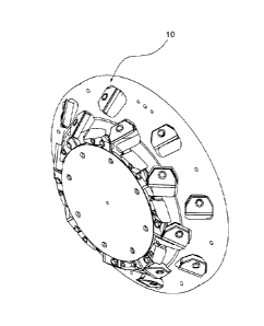
[0025] FIG. 1 is a perspective view of a complete chipping assembly using an
embodiment of replaceable thread inserts in accordance with the principles of
the present
invention.
[0026] FIG. 2 is a side view of an exemplary clamping assembly to be installed
on a
chipping assembly and using an embodiment of replaceable thread inserts in
accordance
with the principles of the present invention.
[0027] FIG. 3 is an exploded perspective view of the knife assembly bolt of
FIG. 2.
[0028] FIG. 4 is a sectional side view of the knife assembly bolt of FIG. 2 as
mounted on
a chipping assembly.
[0029] FIG. 5 is a front view of another exemplary clamping assembly installed
on a
chipping assembly and using an embodiment of replaceable thread inserts in
accordance
with the principles of the present invention.
- 4 -
CA 3050585 2019-07-25
File number 12807-025
[0030] FIG. 6 is a sectional front view of the knife assembly of FIG. 5
showing a knife
holder and a chipping assembly.
[0031] FIG. 7 is a front view of the knife assembly of FIG. 5 showed with the
bolt being
outside of the opening.
[0032] FIG. 8 is a front section view of the knife assembly of FIG. 7 showed
with the
bolt being outside of the opening.
[0033] FIG. 9 is a sectional side view of another embodiment of the knife
assembly bolt
of FIG. 2 as mounted on a chipping assembly.
[0034] FIGS. 10A to 10C are perspective views showing 3 embodiments of a
replaceable
inserts with external friction surface inserts in accordance with the
principles of the
present invention.
[0035] FIG. 11 is a sectional side view of an embodiment of a thread inserts
shown being
inserted in a chipping assembly in accordance with the principles of the
present
invention.
[0036] FIG. 12 is a side view of an embodiment of a tool for removing a thread
inserts
from a chipping assembly in accordance with the principles of the present
invention.
[0037] FIG. 13 is a side section view of the tool of FIG. 12 shown when
pushing on a
thread inserts within the opening of a chipping assembly.
Detailed Description of the Preferred Embodiment
[0038] A novel replaceable thread inserts 60 with external friction surface
and method
will be described hereinafter. Although the invention is described in terms of
specific
illustrative embodiments, it is to be understood that the embodiments
described herein are
by way of example only and that the scope of the invention is not intended to
be limited
thereby.
[0039] As a preliminary matter, it will readily be understood by one having
ordinary skill
in the relevant art ("Ordinary Artisan") that the invention has broad utility
and
application. Furthermore, any embodiment discussed and identified as being
"preferred"
is considered to be part of a best mode contemplated for carrying out the
invention. Other
- 5 -
CA 3050585 2019-07-25
File number 12807-025
embodiments also may be discussed for additional illustrative purposes in
providing a full
and enabling disclosure of the invention. Furthermore, an embodiment of the
invention
may incorporate only one or a plurality of the aspects of the invention
disclosed herein;
only one or a plurality of the features disclosed herein; or combination
thereof. As such,
many embodiments are implicitly disclosed herein and fall within the scope of
what is
regarded as the invention.
[0040] Accordingly, while the invention is described herein in detail in
relation to one or
more embodiments, it is to be understood that this disclosure is illustrative
and exemplary
of the invention, and is made merely for the purposes of providing a full and
enabling
disclosure of the invention. The detailed disclosure herein of one or more
embodiments is
not intended, nor is to be construed, to limit the scope of patent protection
afforded the
invention in any claim of a patent issuing here from, which scope is to be
defined by the
claims and the equivalents thereof. It is not intended that the scope of
patent protection
afforded the invention be defined by reading into any claim a limitation found
herein that
does not explicitly appear in the claim itself.
[0041] Thus, for example, any sequence(s) and/or temporal order of steps of
various
processes or methods that are described herein are illustrative and not
restrictive.
Accordingly, it should be understood that, although steps of various processes
or methods
may be shown and described as being in a sequence or temporal order, the steps
of any
such processes or methods are not limited to being carried out in any
particular sequence
or order, absent an indication otherwise. Indeed, the steps in such processes
or methods
generally may be carried out in various different sequences and orders while
still falling
within the scope of the invention. Accordingly, it is intended that the scope
of patent
protection afforded the invention is to be defined by the issued claim(s)
rather than the
description set forth herein.
[0042] Additionally, it is important to note that each term used herein refers
to that which
the Ordinary Artisan would understand such term to mean based on the
contextual use of
such term herein. To the extent that the meaning of a term used herein¨as
understood by
the Ordinary Artisan based on the contextual use of such term¨differs in any
way from
- 6 -
CA 3050585 2019-07-25
File number 12807-025
any particular dictionary definition of such term, it is intended that the
meaning of the
term as understood by the Ordinary Artisan should prevail.
[0043] With regard solely to construction of any claim with respect to the
United States,
no claim element is to be interpreted under 35 U.S.C. 112(f) unless the
explicit phrase
"means for" or "step for" is actually used in such claim element, whereupon
this statutory
provision is intended to and should apply in the interpretation of such claim
element.
With regard to any method claim including a condition precedent step, such
method
requires the condition precedent to be met and the step to be performed at
least once
during performance of the claimed method.
[0044] Furthermore, it is important to note that, as used herein, "a" and "an"
each
generally denotes "at least one," but does not exclude a plurality unless the
contextual use
dictates otherwise. Thus, reference to "a picnic basket having an apple"
describes "a
picnic basket having at least one apple" as well as "a picnic basket having
apples." In
contrast, reference to "a picnic basket having a single apple" describes "a
picnic basket
.. having only one apple."
[0045] When used herein to join a list of items, "or" denotes "at least one of
the items,"
but does not exclude a plurality of items of the list. Thus, reference to "a
picnic basket
having cheese or crackers" describes "a picnic basket having cheese without
crackers", "a
picnic basket having crackers without cheese", and "a picnic basket having
both cheese
and crackers." When used herein to join a list of items, "and" denotes "all of
the items of
the list." Thus, reference to "a picnic basket having cheese and crackers"
describes "a
picnic basket having cheese, wherein the picnic basket further has crackers,"
as well as
describes "a picnic basket having crackers, wherein the picnic basket further
has cheese."
[0046] The detailed disclosure herein refers to the concept of chipping. In
the present
disclosure, chipping refers to the operation of removing chunks from a log as
opposed to
shredding which refers to reducing or cut into very small strips or reducing
to shreds. In
the present disclosure, chipping may also refer to grinding, which means
rubbing or
wearing an external surface of the wood log, to cutting and/or to reducing.
- 7 -
CA 3050585 2019-07-25
File number 12807-025
[0047] Referring now to FIG. 1, an exemplary chipping head or chipping
assembly 10 is
illustrated. The chipping head or chipping assembly 10 is typically used in a
log chipping
line to create substantially flat surfaces on logs.
[0048] Referring now to FIGS. 2 to 4, an exemplary knife assembly 15 is shown.
In such
an embodiment, the knife assembly 15 comprises a knife holder 30, a knife
clamp 20 and
a knife 40. Broadly, the knife assembly 15 is adapted to mount yet dismount
the knife 40.
The knife assembly 15 is adapted to be mounted on the chipping assembly 10.
[0049] Referring now to FIG. 4, an embodiment of a knife holder 30 is shown
mounted
to the chipping assembly 10. In such an embodiment, the lower portion of the
knife
holder 30 is supported by the chipping assembly 10 on both sides of the
aperture 12.
[0050] Referring now to FIG. 9, another embodiment of a knife holder 30 is
shown. In
such an embodiment, the lower portion of the knife holder 30 is supported only
on one
side of the aperture 12 of the chipping assembly 10. The clamping portion 20
of the knife
assembly 15 being supported by the chipping assembly 10 on the other side of
the
aperture 12.
[0051] Now referring to FIGS. 5 to 8 an embodiment of knife holder 30 adapted
to
receive a bolt 50 to mount the knife holder 30 on the chipping assembly 10 is
shown. In
such an embodiment, the knife holder 30 and the clamp 20 each comprises an
opening 32
and 22 respectively adapted to receive a bolt 50. Understandably, the openings
32 and 22
are shaped to slidingly receive the bolt 50.
[0052] As shown in Figure 8, the bolt 50 first passes through the opening 22
within the
clamp 20 and then in the opening 32 of the knife holder 30. In the embodiments
shown in
FIGS. 5 to 8, the opening 22 of the clamp 20 may comprises an enlarged portion
24
adapted to hold the bolt head 52. The enlarged portion 24 may be slanted,
tapered or may
form a lip or an edge to retain the bolt head 52. When the bolt 50 is inserted
in the
openings 22 and 32, the clamp portion 20 and the knife holder 30 hold the
knife 40 in
position by catching the knife 40 in a vice.
[0053] Referring back to FIG. 2, an exemplary of a knife assembly 15 is shown.
In such
an embodiment, the knife assembly 15 comprises a knife holder 30 having an
opening 32
- 8 -
CA 3050585 2019-07-25
File number 12807-025
substantially perpendicular to the bottom 31 of the knife holder or
substantially vertical.
Such configuration allows accommodating the passage of the bolt 50 through the
knife
holder 30.
[0054] The chipping assembly 10 further comprises one or more inclined or
tapered
plane openings 12 adapted to receive a lower body 54 of the bolt 50. Thus, the
bolt 50
passes through the clamp 20, the knife holder 30 and chipping assembly 10.
[0055] Referring now to FIGS. 5 to 8, the tapered opening 12 of the chipping
assembly
is adapted to receive a tapered insert 60. Understandably, in a typical
embodiment, the
insert 60 comprises a threaded aperture or opening 62 adapted to receive the
threaded
10 body portion 54 of the bolt 50. In some embodiments, the threaded insert
60 has an
external tapered or slanted portion 64 adapted to be received by the tapered
opening 12.
As the threaded body portion 54 of the bolt 50 is tightened in the threaded
opening 62 of
the threaded insert 60, the external tapered surface 64 is pushed again the
mating
receiving tapered opening 12. Such pression creates a force capable of holding
the knife
40 between clamp 20 and the knife holder 30.
[0056] One skilled in the art shall understand that an insert 60 as disclosed
here may be
used in the mounting of any tool or implement adapted to be mounted to the
chipping
assembly 10 and is not limited to mount an exemplary knife holder or knife
assembly to
the chipping assembly 10. Understandably, any other type of tool or implement
known in
the art may be used without limiting the scope of the present invention.
[0057] In other embodiments, as shown in FIGS. 10A to 10C, a nut 70 is adapted
to be
mounted on the one end of the bolt 50 which extends below the threaded insert
60.
[0058] The external surface 64 of the threaded insert 60 and the internal
surface of the
opening 12 are typically shaped or made to allow the threaded insert 60 to
slide in or out
of the opening 12.
[0059] The knife 40 is then held in position by a bolt 50 screwed into the
holder or by a
nut 70 (figure 7) screwed onto the stud 61 (figure 7).
[0060] Referring now to FIGS. 10A to 10C, different embodiments of replaceable
thread
inserts 60 are shown. Referring to FIG. 1, the insert 60 comprises an inside
threaded
- 9 -
CA 3050585 2019-07-25
Ftle number 12807-025
surface 62 and an inclined or tapered outside surface 64. As explained above,
the outside
surface is typically not threaded.
[0061] Referring now to FIG. 10B, a second embodiment of a replaceable thread
insert
160 is shown. The thread insert 160 comprises a threaded stud, pin or shaft
166
protruding from the inside portion 162 of the insert 160. The insert 160 also
comprises an
inclined or tapered plane on the outside surface 164.
[0062] Referring now to FIG. 10C, a third embodiment of a replaceable thread
insert 260
with external friction surface 264 comprises a nut 70 mounted to the bottom
portion of
the insert 260. In some embodiment, the nut 70 is welded to the bottom portion
of the
insert 260. The nut 70 comprises a threaded opening which is substantially
aligned with
the lower opening 262 of the insert 260. The insert 260 further comprises an
inclined or
tapered plane on the outside surface 264.
[0063] Referring now to FIG. 11, an exemplary threaded insert 60 is shown
inserted in
the opening 12 of the chipping assembly 10. In such an embodiment, the angle
of the
inclined or tapered plane openings 12 of the chipping assembly 10
substantially
correspond to the angle of the outside surface 64 of the replaceable thread n
60.
[0064] Preferably, the angle of the inclined or tapered outside plane openings
664, 164
and 264 of the replaceable thread insert 60, 160, 269 ranges between 0.01 and
15 degrees.
[0065] Referring back to FIG. 8, the body portion 54 of the bolt 50 is
preferably screwed
.. into a threaded opening 62 of the replaceable thread insert 60.
[0066] In use, the replaceable thread insert 60, 160, 260 is slid into an
inclined or tapered
plane opening, preferably in an opening 12 of the chipping assembly 10, as
shown in
FIGS. 5 and 6. The knife holder 30 sits on or is received by the chipping
assembly 10.
The knife 40 and the clamp 20 are then positioned. The bolt 50 or the nut 70
can then be
.. inserted on the replaceable thread insert 60, 160, 260.
[0067] A minimum initial torque is then applied on the bolt 50 so the friction
allows the
surface 62, 162, 262 to retain the replaceable thread insert with external
friction surface
60, 160, 260 as shown in FIGS. 6.
- 10 -
CA 3050585 2019-07-25
File number 12807-025
[0068] Once the assembly has been completed, the nominal torque is applied to
the bolt
50 or the nut 70. After nominal torque is applied, the knife assembly 15 may
be loosened
to replace or turn the knife 40 to obtain a new cutting edge.
[0069] The replaceable thread insert 60, 160, 260 will remain in position
during changes
of knife 40.
[0070] The replaceable thread insert 60, 160, 260 may be completely removed
from the
opening 12 to complete its maintenance.
[0071] To remove the replaceable thread insert 60, 160, 260, one may remove
the bolt 50
or the nut 70 by untightening it. Once the bolt 50 or nut 70 is removed, the
replaceable
thread insert 60, 160, 260 is generally stuck or retained within the opening
12 of the
chipping assembly 10. By being maintained in the opening 12, the insert 60,
160, 260
may drop or fall being the chipping assembly. After the bolt 50 or nut 70 is
removed, the
clamp 20 is removed from the top of the knife 40. The released knife 40 may
then be
removed followed by the knife holder 30.
[0072] When the bolt 50, the clamp 20, the knife 40 and the knife holder 30
are removed,
the replaceable thread insert 60, 160, 260 may be disengaged. In some
embodiments, the
bolt 50 or the nut 70 are threaded along the entire length of the body 54. A
blunt mass or
any tool to provide an impact force is used to hit the head 52 of bolt 50 or
the nut 70 to
disengage the replaceable thread insert 60, 62 from the chipping assembly 10.
One skilled
in the art shall understand that when the bolt 50 or nut 70 is loosened, some
space is
created between the head 52 and the receiving portion 24 of the clamp 20.
[0073] When an insert 160 is used, it is then necessary to hit the stud 160
with a blunt
mass to disengage the replaceable thread insert 61 from the chipping assembly
10.
[0074] One may then use the previous method to install a new replaceable
thread insert
60, 160, 260 on the chipping assembly 10.
[0075] Preferably the material used for making the replaceable thread insert
with external
surface 60, 160, 260 may be selected from corresponding material family to the
head 52.
The selected material generally aims at creating a frictional jamming between
the insert
60, 160, 260 and the opening 12.
- 11 -
CA 3050585 2019-07-25
File number 12807-025
[0076] Referring now to Figures 12 and 13, a tool 300 for dislodging a thread
insert 60 is
shown. The tool 300 generally comprises a main body 320 and elongated member
330
extending within the said body 320. The elongated member 330 is shaped to fit
within the
opening or passage 62 of a thread insert 60 at one end and to tit within the
opening 12 of
the chipping assembly 10 at another end. The elongated member 330 comprises a
top
portion 333, and a lower portion 334. The top portion is shaped to fit within
the opening
12 of the chipping assembly. The lower portion is shaped to fit within the
opening or
passage 62 of a thread insert 60. Understandably, the top portion is wider
than the lower
portion. The width or diameter of the top portion of the elongated member 330
must be
smaller than the opening 12 of the chipping assembly 10 but greater than the
opening 62
of the insert 60. In some embodiments, the elongated member 330 is shaped as a
cylinder.
The elongated member 330 generally comprises a lip or edge formed between the
top
portion and the lower portion. Such edge allows the elongated member 330 to be
pushed
against the top portion of the insert 60.
[0077] The tool 300 further comprises a butt 350 at one extremity. The butt
350 is
adapted to receive a strike from any type of hammer, mallet or the like. In
some
embodiments, the butt 350 is a disk attached to the top portion of the
elongated member
330. In the embodiment as shown in FIG. 12, the butt 310 is welded to the top
portion of
the elongated member 330.
[0078] In some embodiments of the tool 300, a casing or handle 320 is provided
to
slidingly receive the elongated member 330. The casing 320 may further
comprises a
dampening portion 350, such as an 0-ring, adapted to absorb the shock of the
310 against
the casing. Understandably, the casing may have any shape suited to be used
with the
particulars of chipping assemblies 10.
[0079] The elongated member 330 may comprise a retaining portion 340 at its
extremity.
The retaining portion is adapted to hold on the dislodged insert 60 to avoid
losing it under
the chipping assembly 10. In some embodiments, the retaining portion 340 is a
spring pin
340 generally adapted to have a length or width being greater than the width
or diameter
of the opening 62 of the thread insert 60. Typically, the spring pin 340 is
inserted in an
aperture or passage across the elongated member 330. Understandably, any other
- 12 -
CA 3050585 2019-07-25
File number 12807-025
mechanism known in the art to allow the thread insert 60 to be held on the
elongated
member 330 after being dislodged may be used with the present invention.
[0080] In use, the elongated member 330 of the tool 300 is inserted within the
apertures
12 and 62 of the chipping assembly 10 until the edge contacts the top portion
of the insert
60, the lower portion of the elongated member being inserted in the aperture
62 of the
insert 60 only. In a typical embodiment, prior to inserting the tool 300, the
knife assembly
is removed from the chipping assembly 10 as it is not longer held by the bolt
50. After
being inserted, a hammering tool is used to hit the butt 350 of the tool 300.
Such an
impact dislodges the insert 60 from the aperture 12 of the chipping assembly
10.
10 .. [0081] In other embodiments, after being inserted, the retaining member
340 is installed
on the extremity of the lower portion being outside of the aperture 62 of the
insert 60.
[0082] In yet other embodiments, a user may hold the tool 300 by having the
casing 320
in hand and hitting on the butt 350 of the tool. Such impacts force the
elongated member
330 to slide within the casing 320 to provide a force to dislodge the insert
60.
15 [0083] While illustrative and presently preferred embodiments of the
invention have been
described in detail hereinabove, it is to be understood that the inventive
concepts may be
otherwise variously embodied and employed and that the appended claims are
intended to
be construed to include such variations except insofar as limited by the prior
art.
- 13 -
CA 3050585 2019-07-25