Note: Descriptions are shown in the official language in which they were submitted.
CA 03050617 2019-07-17
WO 2018/134591 PCT/GB2018/050136
1
URINARY CATHETER
This invention relates to urinary catheters.
Urinary catheters are used to assist or control the flow of urine from the
bladder of a
patient. When a patient needs to use a catheter for an extended period of
time, they
may use an indwelling urinary catheter. An indwelling urinary catheter has a
tube
which is introduced through the patient's urethra or directly via an abdominal
incision
(supra-pubic catheter). Once the distal tip of the catheter is in the bladder
it is retained
in position by means such as a balloon inflated within the bladder. A lumen
extending
through the catheter can then drain urine from the bladder.
A common design of indwelling urinary catheter is the Foley catheter. In the
Foley
catheter, the balloon is toroidal in shape and is located proximally of the
catheter tip.
A drainage opening which communicates with the lumen is located between the
catheter tip and the balloon. Catheters of this design suffer from a number of
problems. The tip of the catheter is exposed and can irritate the bladder
wall. Material
of the bladder wall can become drawn into the drainage opening, causing
discomfort
and mucosal damage. The drainage opening is spaced from the base of the
bladder
by the balloon, which prevents the bladder draining completely leading to a
residual
pool of urine that can become infected.
WO 2015/028786 discloses one approach to addressing at least some of these
problems. It provides a urinary catheter having an inflatable balloon which
extends
over the tip of the catheter. WO 2007/005734 discloses another design of
urinary
catheter, in which the drainage opening extends proximally of the inflatable
balloon.
There is a need for an improved design of urinary catheter.
According to one aspect of the present invention there is provided a catheter
comprising: a shaft having a proximal end and a distal end, the distal end
terminating
CA 03050617 2019-07-17
WO 2018/134591 PCT/GB2018/050136
2
in a tip; a drainage opening located at the distal end of the shaft, the
drainage opening
communicating with a drainage lumen of the shaft; a balloon located at the
distal end
of the shaft, the balloon comprising a first region secured to the shaft, a
second region
secured to the shaft and an elastic-walled and/or flexible-walled conduit
extending
between the first region and the second region, the elastic-walled conduit
extending
over the tip.
At least part of the first region may be located proximally of the drainage
opening. At
least part of the second region may be located proximally of the drainage
opening.
At least a part of the balloon is in the form of an elongate tube. That part
may comprise
the elastic- and/or flexible-walled conduit.
The first region may be at one end of the tube and the second region may be at
the
other end of the tube.
The catheter may be such that: the balloon is in its uninflated state; the
tube has
lateral edges; the balloon comprises an outer layer defining the exterior of
the balloon
in its uninflated state; and the balloon is folded so that the lateral edges
are located
between the outer layer and the shaft of the catheter. In a state of the
catheter prior
to inflation and/or use, lateral edges of the conduit may be sandwiched
between a
central portion of the conduit and the shaft of the catheter, for example
between the
central portion of the conduit and a part of the catheter shaft that is any
one or more
of (i) a distal part of the shaft of the catheter, (ii) the tip of the
catheter, and (iii) a lateral
portion of the shaft of the catheter.
The first and second regions may overlap.
The first region and/or the second region may span an arc of greater than 90
degrees
around the longitudinal axis of the catheter.
CA 03050617 2019-07-17
WO 2018/134591 PCT/GB2018/050136
3
The first region and/or the second region may span an arc of greater than 180
degrees
around the longitudinal axis of the catheter.
The catheter may comprise an inflation opening located at the distal end of
the shaft.
The inflation opening may communicate with an inflation lumen of the shaft and
with
the interior of the balloon.
The balloon may comprise two walls where it extends over the tip. The region
between
the walls may communicate with the inflation opening. There may be additional
layers
of elastic or inelastic material externally of the balloon.
The balloon may be configured such that when inflated an exterior wall of the
balloon
is located distally of and spaced from the tip of the catheter.
The balloon may be configured such that when inflated an interior wall of the
balloon
bears against the tip of the catheter.
The drainage opening may be located on a side of the catheter shaft. The
balloon
may be configured such that, when it is inflated, regions of the exterior of
the balloon
are located laterally outward of that side of the catheter shaft on either
side of the
drainage opening.
The balloon may be configured such that, when it is inflated, regions of the
exterior of
the balloon are located radially outward of the catheter shaft proximally of
the most
proximal part of the drainage opening.
The balloon may be configured such that, when it is inflated, regions of the
exterior of
the balloon extend radially outward with respect to the longitudinal axis of
the catheter
shaft around the majority of the or each drainage opening.
The balloon may be formed of a material that has a tendency to adhere to
itself.
CA 03050617 2019-07-17
WO 2018/134591 PCT/GB2018/050136
4
The ratio of (i) the mean diameter of the catheter shaft immediately distal of
the
drainage opening to (ii) the distance from the most distal part of the first
region to the
tip of the catheter may be in the range from 0.8:1 to 3:1 alternatively from
1:1 to 2.5:1,
alternatively from 1.2:1 to 2:1, alternatively from 1:2 to 2:1.
The material forming the wall of the balloon may be of uniform elasticity
across its
area, or of non-uniform elasticity across its area. The wall of the balloon
may comprise
one or more thickened regions such as ribs for reducing the elasticity of the
wall
adjacent thereto.
The balloon may be secured to the shaft at the first and second regions by a
mechanical fixing clamping the balloon to the shaft. The mechanical fixing
may, for
example, be a collar surrounding the shaft. The balloon may in addition be
attached
to the shaft by adhesive.
The balloon may be configured so that when the balloon is inflated, a wall of
the
balloon facing the tip is spaced from the tip. The drainage opening may open
distally
from the tip.
When the balloon is in its uninflated state, material of the balloon may be
stowed in
the drainage lumen.
According to a second aspect of the present invention there is provided a
method for
manufacturing a catheter comprising: providing a shaft having a proximal end
and a
distal end, the distal end terminating in a tip, a drainage opening located at
the distal
end of the shaft, the drainage opening communicating with a drainage lumen of
the
shaft and an inflation opening located at the distal end of the shaft, the
inflation opening
communicating with an inflation lumen of the shaft; providing an elastic-
walled conduit
having an access opening to the interior thereof; securing a wall of the
conduit to the
shaft around the inflation opening; introducing a tool through the access
opening;
piercing the wall of the conduit with the tool at the location of the
inflation opening; and
closing the access opening.
CA 03050617 2019-07-17
WO 2018/134591 PCT/GB2018/050136
The method may further comprise: locating the elastic-walled conduit over the
tip of
the catheter; and securing a wall of the conduit to the shaft on the opposite
side of the
shaft to the inflation opening.
The conduit may be attached to the shaft of the catheter such that the
interior of the
of the conduit communicates in a fluid-tight manner with the inflation lumen.
The
conduit may be fluid-tight except for an aperture to the inflation opening A
valve may
be located in the inflation lumen. The valve may be capable of resisting flow
of fluid
from the distal end of the shaft to the proximal end of the shaft.
The catheter may be a urinary catheter. The catheter may be an indwelling
urinary
catheter.
Parts of the elastic-walled conduit may be inelastic.
The conduit may be located distally of the tip. In an inflated state of the
balloon a wall
of the conduit immediately distal of the tip may contact or may be spaced from
the tip.
When the balloon is in an inflated state, the tip may be in contact with
material of the
balloon or may be exposed.
The conduit may be integral with the first and second regions.
The shaft may be an elongate shaft.
The present invention will now be described by way of example with reference
to the
accompanying drawings. In the drawings:
Figure 1 is an isometric view of a urinary catheter without a balloon in
place.
Figure 2 is a cross-section of the shaft of the catheter of figure 1 on line A-
A.
CA 03050617 2019-07-17
WO 2018/134591 PCT/GB2018/050136
6
Figure 3 is a cross-section of the distal part of catheter of figure 1 on line
B-B, with a
partially inflated balloon in place.
Figure 4 is a cross-section of the distal part of the catheter of figure 1 on
the line C-C
of figure 3, with a partially inflated balloon in place.
Figure 5 is an isometric view of the distal part of the catheter of figure 1,
with a partially
inflated balloon in place.
Figure 6 is a cross-section of the distal part of catheter of figure 1 on line
B-B, with a
fully inflated balloon in place.
Figure 7 is a side view of the distal part of catheter of figure 1, with an
uninflated
balloon in place.
Figure 8 is an isometric view of the distal part of a catheter with a T-shaped
balloon.
Figures 9 and 10 show steps in the manufacture of a balloon for a catheter.
Figure 11 is a cross-section of the distal part of catheter of figure 1 on
line B-B, with
an uninflated balloon of a first design in place.
Figure 12 is a cross-section of the distal part of catheter of figure 1 on
line B-B, with
an uninflated balloon of a second design in place.
Figure 13 is an isometric view of an alternative embodiment of catheter.
Figure 1 shows a urinary catheter having a shaft 1. The catheter shaft has a
proximal
end 2. The proximal end is intended to sit outside the body when the catheter
is in
use. The catheter has a distal end 3. The distal end is intended to sit in the
bladder
of a user when the catheter is in use. The distal end of the catheter
terminates in a tip
4. Two openings are defined in the distal end of the catheter. An inflation
opening 5
CA 03050617 2019-07-17
WO 2018/134591 PCT/GB2018/050136
7
is intended for inflating a balloon which can be attached to the catheter. The
inflation
opening communicates with an inflation lumen 6 which runs along the shaft. A
drainage opening 7 is intended for draining urine from the bladder of a user.
The
drainage opening communicates with a drainage lumen 8 which runs along the
shaft.
There may be multiple drainage openings in the distal end of the catheter.
Preferably
each drainage opening communicates with the drainage lumen 8. Figure 2 shows a
cross-section of the shaft on line A-A of figure 1, illustrating the lumens 6,
8. At the
proximal end of the shaft, the inflation opening communicates with an
inflation port 9
and the drainage opening communicates with a drainage port 10. Fluid can be
introduced through the inflation port 9 to then pass through the inflation
opening 5.
Urine received through drainage opening 7 can be collected through drainage
port 10.
A collecting vessel can be attached to the drainage port.
In the examples shown in the figures, the inflation opening 5 and the drainage
openings 7 overlap in the longitudinal axis of the catheter. There could be
multiple
inflation openings. The or each inflation opening could be distal of the
drainage
opening, or of a subset of the drainage openings or of all the drainage
openings. The
or each inflation opening could be proximal of the drainage opening, or of a
subset of
the drainage openings or of all the drainage openings. Configuring the
catheter shaft
so that the inflation opening(s) do/does not overlap the drainage opening(s)
in a
longitudinal direction may help to improve the strength of the shaft.
The entirety of the distal end may taper to the tip, or the distal part of the
distal end
may taper to the tip; or the distal end may be of constant diameter about the
longitudinal axis of the catheter, in which case the tip may be generally
hemispherical.
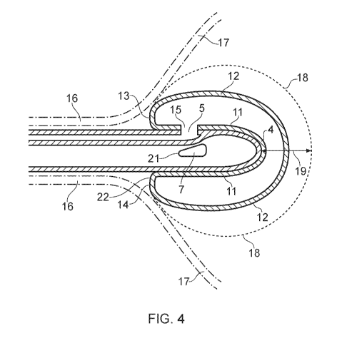
Figure 3 is a cross-section of the distal part 3 of the shaft on line B-B of
figure 1, with
a partially inflated balloon (not shown in figure 1) installed on the shaft.
Figure 4 is a
cross-section on line C-C of figure 3, and figure 5 is an isometric view
showing the
partially inflated balloon. The catheter of figure 2 has two drainage openings
7. The
balloon is generally in the form of a tube having an internal wall 11 and an
external
wall 12. The tube is generally elongate, extending between ends 13, 14. The
balloon
CA 03050617 2019-07-17
WO 2018/134591 PCT/GB2018/050136
8
is made of an elastic sheet material. The tube constitutes a conduit part or
all of whose
walls are elastic and/or flexible. The balloon is sealed except for an
aperture 15 near
one of its ends (end 13), by which the interior of the balloon communicates
with the
inflation opening 5. The balloon is sealed to the shaft 1 of the catheter
around the
inflation opening. As a result, the balloon can be inflated by introducing
fluid such as
water or air into the balloon through the aperture 15. The tube-like form of
the balloon
extends over the tip 4 of the catheter. The balloon is bent around the tip 4.
The end
14 of the balloon remote from the aperture 15 is also attached to the distal
end of the
catheter shaft. This holds the balloon bent over the tip.
Figure 4 is a cross-section of the distal part of the catheter on line C-C.
Figure 4 shows
the balloon in its partially inflated state. Figure 4 shows in chain-dotted
lines the
urethra 16 and bladder wall 17 of a person into whom the catheter has been
inserted;
and dotted line 18 indicates the exterior form of the balloon in its fully
inflated state. It
should be noted that in its fully inflated state the balloon might be capable
of further
inflation (i.e. over-inflation). The fully inflated state is the state in
which it would
normally be left indwelling in a patient's bladder. In its fully inflated
state, the size of
the balloon, whose outer wall extends radially outward from the shaft of the
catheter,
resists withdrawal of the catheter through the urethra. This retains the
distal end of
the catheter in the bladder. The balloon can also form a seal at the base of
the bladder
to resist leakage of urine past the catheter.
Before the catheter is used, a reservoir containing a predetermined volume of
fluid can
be engaged with the inflation port. The reservoir could be a syringe or a bag.
Once
the tip of the catheter is in place in the bladder, the fluid can be squeezed
from the
reservoir into the balloon. The predetermined volume of fluid can be such as
to cause
the balloon to be fully inflated when the reservoir is fully evacuated. A
valve may be
provided exists in the inflation lumen to resist fluid flow in the inflation
lumen towards
the proximal end of the catheter. This can help the balloon to remain
inflated.
As noted above, the balloon is in the form of an elongate tube folded over the
tip of
the catheter. The ends of the tube are attached to the catheter shaft on
either side of
CA 03050617 2019-07-17
WO 2018/134591 PCT/GB2018/050136
9
the distal end of the catheter. In this example, the attachment points are
proximal of,
and on either side of, the drainage opening. In other embodiments the
attachment
points may overlap the drainage opening(s) or be distal to them. The balloon
is formed
of an elastic sheet material. When the balloon is inflated, the sheet material
stretches.
This arrangement of the balloon may provide any one or more of the following
effects.
1. When the balloon is inflated, the outer skin of the balloon is extended
distally of the
distal tip 4 of the catheter shaft, along the longitudinal axis of the
catheter shaft, as
indicated at 19 in figure 4. This can help to cushion the wall of a patient's
bladder
against contact with the tip. The fact that the balloon tube folds over the
tip of the
catheter means that there are two walls of the balloon overlying the tip. When
the
balloon is inflated the interior wall of the balloon contacts the tip, forcing
the exterior
wall to be spaced from the tip.
2. When the balloon is inflated, the inner wall of the balloon is pressed
against the tip
and the distal side walls of the catheter. Because the exterior of the
catheter is convex
where it contacts the balloon, the contact between the catheter and the
balloon
introduces a concavity to the interior wall of the balloon. This engagement
between
the catheter and the balloon can help to resist the balloon slipping off the
tip when the
balloon is inflated. This can avoid the need to adhere the balloon to the
shaft over the
balloon's whole length of contact with the shaft. Preferably the balloon is
unadhered
to the shaft distally of the most distal point of the or each drainage
opening. Preferably
the balloon is unadhered to the shaft distally of the most proximal point of
the or each
drainage opening.
3. Figure 6 is a cross-section of the distal part of the catheter on the plane
of figure 3,
showing the balloon in its fully inflated state. When the balloon is inflated,
the outer
skin of the balloon is extended laterally of the drainage opening as indicated
at 20.
This can help to protect the patient's bladder wall against being drawn into
the
drainage opening. This effect can be promoted by the fact that the balloon
tube is
attached to the catheter shaft proximally of and on either side of the
drainage opening.
4. When the balloon is inflated, the proximal end 21 of the drainage opening 7
is close
in the longitudinal direction of the catheter shaft to the most proximal point
22 at which
the balloon's outer wall is extended laterally from the catheter shaft. That
point is
capable of being located substantially at the neck of the bladder. As a
result, the
CA 03050617 2019-07-17
WO 2018/134591 PCT/GB2018/050136
drainage opening itself can be located close to the neck of the bladder. This
means
that there is little scope for undrained urine to pool at the base of the
bladder.
Various configurations for the balloon will now be described in more detail.
The balloon has an uninflated state. This may be the balloon's state when the
catheter
is packaged for supply to a user. The catheter having the balloon applied
thereto in
its uninflated state may be packaged in a sealed package whose interior is
sterile.
In its uninflated state, the balloon may take the form of a tube, for instance
a flattened
tube, having a greater length than its width. The balloon may be of uniform
width, or
it may vary in width along its length.
The shaft of the catheter may be formed of a material such as polyurethane, a
silicone
elastomer or latex. A polyurethane catheter shaft can be more rigid than
comparable
rubber catheter shafts. This can allow the shaft to have a larger urine
carrying capacity
without sacrificing rigidity for insertion.
The exterior and/or interior surfaces of the shaft and/or the drainage
openings may be
coated with a hydrogel coating. Such coatings are produced, for example, by
Covalon
Technologies Ltd. The application of such a coating to the interior surfaces
may result
in a smoother interior surface which may reduce encrustation. Alternative
coatings
may for example contain silver or Nitrofurantoin.
The walls of the balloon may be formed of a material such as polyurethane, a
silicone
elastomer or latex. The walls of the balloon may be elastic or flexible or
both. The
walls of the balloon may include one or more regions of greater elasticity
and/or
flexibility than one or more other regions of the walls. The exterior surface
of the
balloon may be coated with an antimicrobial agent such as an inert hydromer.
The
walls may be uniformly elastic across their area, or their Young's modulus may
vary
across their area. The walls may be uniformly biaxially elastic, or regions of
the walls
may have different Young's moduli in different directions. Varying the Young's
CA 03050617 2019-07-17
WO 2018/134591 PCT/GB2018/050136
11
modulus of the walls across their area can allow the shape of the balloon as
it expands
to be controlled. The walls of the balloon may be of uniform thickness or they
may be
provided with thickened regions such as ribs. Such thickened regions may
influence
the shape of the balloon as it expands.
In its uninflated state the balloon extends over the distal tip of the
catheter. One or
more regions of the balloon may be attached to the shaft of the catheter. One
region
of attachment may surround the inflation opening 5. The balloon may have an
aperture
in its wall facing the inflation opening. The aperture may communicate with
the
inflation opening. In this way the balloon can be sealed around the inflation
opening
to permit pressure in the balloon to be increased by fluid flow through the
inflation
opening.
In a first configuration, as shown in figure 5, the balloon is in the form of
a tube which
curves over the tip of the catheter. The tube defines legs 23 which extend
along the
sides of the shaft of the catheter. The balloon is attached to the shaft of
the catheter
on either side of the tip. Preferably the regions of attachment are
diametrically
opposite each other with respect to the shaft, but they may be offset.
Preferably the
regions of attachment are equidistant from the tip of the catheter, but they
could be at
different distances from the tip. The balloon may be attached to the shaft by
adhesive,
by welding (e.g. thermal welding) or by a mechanical fixing such as a collar
configured
to clamp the balloon to the exterior of the catheter shaft. The collar may
serve the
purpose of securing to the balloon to the shaft. It may be supplemented by
adhesive
or welding between the balloon and the shaft. The collar may serve the purpose
of
improving the inflation of the balloon. The collar may surround the balloon
proximally
of the or each inflation opening, thereby inhibiting inflation of the proximal
parts of the
balloon. This may improve the shape of the inflated balloon. Figure 7
illustrates one
arrangement. The legs 23 of the balloon are attached to the shaft of the
catheter
proximally of the drainage opening 7, in region 24. The lateral edge of a
first one of
the legs is denoted at 25. The lateral edge of the other one of the legs is
denoted at
26. In this example, the first leg overlaps the other leg in the region of
attachment 24.
This can help to promote the balloon adopting, when inflated, a passageway
between
CA 03050617 2019-07-17
WO 2018/134591 PCT/GB2018/050136
12
the edges 25, 26, around the drainage opening, of a size that permits the flow
of urine
into the drainage opening but is sufficiently small that it helps keep the
bladder wall
from being drawn into the drainage opening. In another embodiment the two legs
of
the balloon meet on both sides along the circumference. In another embodiment
the
two legs meet at opposite edges of one or two urine draining ports. These
port(s) might
extend more distally than the attachments of the legs to enhance urine
drainage.
There may be one, two or more drainage openings. Preferably, there is a
drainage
opening between each leg of the balloon as it extends along the side of the
catheter
shaft.
There may be one, two or more inflation openings. The balloon may be inflated
from
a single end or from more than one end.
It is desirable for the outer surface of the balloon, when the balloon is
fully inflated, to
have the following properties.
(i) To be spaced from the catheter shaft around the or each drainage opening,
to resist
the bladder wall being drawn into the drainage openings.
(ii) To define, for the or each drainage opening, a passage located outboard
of that
drainage opening through which urine can flow from the volume of the bladder
into the
drainage opening.
It has been found that these characteristics are promoted if the regions where
the
balloon is adhered to the catheter shaft have any one or more of the following
properties:
- they are each located wholly or partially proximally of the proximal end
of the drainage
opening that lies between them;
- they overlap proximally of any drainage opening that lies between them.
An arrangement of this type is shown in figure 7.
In the catheter of figures 2 to 7 the balloon is an elongate tube which, when
folded
over the catheter tip has two legs. Alternatively, the balloon may be branched
and
may have more than two legs extending along the side of the catheter shaft.
CA 03050617 2019-07-17
WO 2018/134591 PCT/GB2018/050136
13
In another configuration, as shown in figure 8, the balloon is in the form of
a T-shaped
tube. A central element of the tube curves over the tip of the catheter
forming legs 27,
28. At the proximal end of leg 27 the tube has a pair of cross-elements 29.
When the
balloon is inflated, those cross-elements extend around the shaft 1 of the
catheter.
The cross-elements can help the inflated balloon to seal around the neck of
the
bladder. The balloon may be attached to the catheter shaft at locations 30, 31
at the
proximal ends of legs 27, 28. Other configurations are possible. Cross-
elements
could extend from both legs of the balloon. A leg of the balloon could have a
single
cross-element extending from it.
It is desirable for there to be a relatively small spacing between the
proximal end of
the balloon, when inflated, and the proximal end(s) of the or each drainage
opening.
This promotes relatively complete draining of the bladder. To this end, it is
preferred
that the proximal free region of the outer skin of the balloon (i.e. the
proximal part of
the outer skin that is not directly adhered to the catheter shaft) is located
between 0
and lOmm proximally of the most proximal part of the or each drainage opening,
more
preferably between 2 and 8mm proximally of the most proximal part of the or
each
drainage opening.
It is desirable for the balloon to resist being dislodged from the tip of the
catheter,
especially when the balloon is in an inflated state. This may be promoted in a
number
of ways. First, the balloon may be configured so that in its uninflated state
and/or in
its fully inflated state each leg of the balloon that extends along the
catheter shaft
contacts the catheter shaft around an arc of more than 90 degrees about the
longitudinal axis of the shaft. In this configuration, the inner surface of
the balloon can
adopt a concavity about the shaft which physically resists it being dislodged
from the
shaft. The arc may more preferably be greater than 110 degrees or greater than
130
degrees or greater than 150 degrees. This may be achieved by the respective
leg of
the balloon being adhered to the shaft around an arc of more than 90 degrees,
more
than 110 degrees, more than 150 degrees or more than 180 degrees about the
longitudinal axis of the shaft. Second, a region of the catheter shaft located
CA 03050617 2019-07-17
WO 2018/134591 PCT/GB2018/050136
14
longitudinally between the catheter tip and a region of attachment of a part
of the
balloon may be treated to increase its friction against the balloon. For
example, it may
be roughened in comparison to the remainder of the catheter shaft, or it may
be coated
with or formed of a relatively high-friction material such as a rubber. Third,
the balloon
may be attached to the catheter shaft distally of the drainage opening, e.g.
by adhesive
or welding. Fourth, it has been found that when the ratio of (i) the mean
diameter of
the catheter shaft immediately distal of the drainage opening to (ii) the
longitudinal
distance between the tip of the catheter and the most proximal free region of
the outer
skin of the balloon is in the region of 1.5:1 the balloon can naturally tend
to remain in
place on the tip. That ratio may for example be in the range from 1:1 to
2.5:1. To
assist this effect, preferably the catheter shaft tapers smoothly toward the
tip from the
region immediately distal of the drainage opening.
The balloon may be formed from a continuous tube of elastic material. The tube
may
be extruded or drawn into shape. Alternatively, the tube may be formed of a
single
sheet of material which is folded so its lateral edges meet, the lateral edges
then being
joined together. Figures 9 and 10 illustrate other ways in which the catheter
can be
manufactured.
In the method of figure 9, the balloon is formed of two sheets 50, 51 of
elastic material.
Sheet 51 defines an aperture 52. One sheet is placed on top of the other, and
the
sheets are joined together around their peripheries, as shown at 53. This may
be
done, for example, by adhesive or by welding. In this example, the sheets are
elongate
and of uniform width, resulting in the balloon being in the form of a tube of
uniform
width, but the sheets could be of other shapes. After the sheets, one of which
already
defines the aperture 52, have been welded together, the balloon is attached to
the
catheter shaft. The balloon is attached to the shaft by joining the periphery
of the
aperture 52 to the shaft continuously around the inflation opening 5. This
forms a fluid-
tight seal between the interior of the balloon and the inflation lumen. The
balloon is
wrapped over the tip of the catheter and further attached to the shaft on the
opposite
side of the shaft to the inflation opening.
CA 03050617 2019-07-17
WO 2018/134591 PCT/GB2018/050136
In the method of figure 10, the balloon is formed of two sheets 54, 55 of
elastic
material. Neither sheet defines an aperture at this stage. The sheets are
joined
together around their peripheries as indicated at 56, leaving an opening at 57
through
which the region between the sheets can be accessed. Then the balloon is
attached
to the shaft by adhering part of the exterior surface of sheet 55 to the shaft
continuously
around the inflation opening 5. Then a tool is introduced through opening 57
to pierce
the sheet 55 where it overlaps the inflation opening. Then the opening 57 is
sealed
by joining the sheets 54, 55 together across the opening. This closes the
balloon to
form a fluid-tight volume except for its connection to the inflation lumen
through an
aperture pierced by the tool. The balloon is wrapped over the tip of the
catheter and
further attached to the shaft on the opposite side of the shaft to the
inflation opening.
In summary, in the method of figure 9 an aperture for communicating with the
inflation
opening is formed before the balloon is attached to the catheter shaft, and in
the
method of figure 10 an aperture for communicating with the inflation opening
is formed
after the balloon is attached to the catheter shaft.
In the method described above with reference to figure 10, a catheter is
provided with
an inflation opening, the balloon is attached to the catheter around the
inflation
opening, and a tool is used to pierce the balloon at the site of the inflation
opening. In
an alternative process, the catheter may be provided without in inflation
opening and
the tool may pierce both the balloon and the catheter wall after the balloon
has been
attached to the catheter.
Thus, in this alternative method, the method may comprise providing a shaft
having a
proximal end and a distal end, the distal end terminating in a tip, a drainage
opening
located at the distal end of the shaft, the drainage opening communicating
with a
drainage lumen of the shaft; providing an elastic-walled conduit having an
access
opening to the interior thereof; securing a wall of the conduit to the shaft;
introducing
a tool through the access opening; piercing the wall of the conduit with the
tool;
piercing the shaft to form an inflation opening located at the distal end of
the shaft, the
CA 03050617 2019-07-17
WO 2018/134591 PCT/GB2018/050136
16
inflation opening communicating with an inflation lumen of the shaft; and
closing the
access opening.
In a further alternative process, a punch may be used to create not only the
access to
the inflation lumen through the balloon, but also then to punch a hole in one
wall of the
balloon. Glue may then be applied around the hole in the balloon and this part
of the
balloon may be presented to the shaft to secure it.
When the balloon is formed from two sheets of material, they may be sheets of
the
same material or of different materials. When the sheets are of different
materials,
they could both be elastic materials, or the sheet forming the inner wall
could be a
sheet of a relatively inelastic material and the sheet forming the outer wall
could be a
sheet of a relatively elastic material.
Ways in which the balloon can be provided in its uninflated state will now be
described.
Figure 11 is a cross-section at line B-B of figure 1 with an uninflated
balloon in place
on the catheter shaft. In this example the balloon is pressed against the
shaft so as
to define an inner wall 58 and an outer wall 59. Inner wall 58 can be affixed
to the
catheter shaft. The walls are joined together along their lateral edges, as
indicated at
60. The inner wall is sealed to the shaft around the inflation opening at
regions 61.
Figure 12 is a cross-section on an analogous plane to figure 11. Figure 12
shows a
balloon whose lateral edges are folded under the outer layer of the balloon.
The
outermost layer of the balloon in its uninflated state is indicated at 62. The
lateral
edges 63 of the balloon are folded away from the outermost layer 62. The
lateral
edges are located between the outer layer 62 and the catheter shaft 1. The
lateral
edges comprise two layers of the balloon. As a result, when the balloon is
inflated,
the lateral edges expand out from under the outermost layer 62. This can allow
the
balloon more freedom to expand than in the arrangement of figure 11. Providing
additional balloon material in this way can allow the balloon to adopt a
larger size than
it would otherwise do for a given degree of stretch. In the arrangement of
figure 12,
CA 03050617 2019-07-17
WO 2018/134591 PCT/GB2018/050136
17
there are more than two thicknesses of the material of the balloon at some
points
overlying the catheter stem. The balloon is sealed to the shaft around the
inflation
opening at regions 64.
Figure 7 shows a balloon having this folded-under configuration. If can be
seen from
figure 12 that the folded-under lateral edges 63 terminate at their central
ends at fold
lines 65. Those fold lines are shown in figure 7. As indicated in figure 7,
the width of
the portion of the balloon that is folded under the outermost layer may
increase
towards the tip of the catheter shaft. It has been found that this is helpful
in promoting
a desirable form of balloon in its inflated state.
Figure 13 shows an alternative embodiment of urinary balloon catheter with the
balloon in its inflated state. The distal end of the catheter is shown
generally at 70.
The shaft 71 of the catheter comprises an inflation lumen 72 and a drainage
lumen 73.
These extend along the shaft of the catheter towards the proximal end in the
same
way as is shown in figure 1. At the distal end, the inflation lumen terminates
in an
inflation opening 74 and the drainage lumen terminates in a drainage opening
75. A
balloon indicated generally at 76 is located at the distal end of the
catheter. The
balloon is configured so as to have multiple side channels 77, 78, 79 which,
when
inflated, will run in the longitudinal direction of the catheter from a
respective
attachment point 80, 81 on the shaft of the catheter proximally of the tip to
a region 82
where the channels join and intercommunicate. At least one of the channels (in
this
example that is channel 77) communicates with the or an inflation port. The
proximal
ends of the channels are sealed. The or each channel through which inflation
can
take place is sealed around the respective inflation opening. The balloon is
configured
so that the intercommunication region 82 is located distally of the tip of the
catheter.
In one example, the side channels may be configured such that when the balloon
is
inflated the interior wall 83 of the material defining the intercommunication
region 82
contacts the tip of the catheter. In that case the drainage opening may be
located in
the side of the catheter shaft, as for the embodiments of figures 1 to 12.
Alternatively,
the side channels may be configured such that when the balloon is inflated the
interior
wall 83 of the material defining the intercommunication region 82 is spaced
from the
CA 03050617 2019-07-17
WO 2018/134591 PCT/GB2018/050136
18
tip of the catheter. This is shown in figure 13. In this case, the drainage
opening may
be located at the tip of the catheter, as shown in figure 13. This drainage
opening is
located in the tip of the catheter. The drainage opening opens distally from
the tip.
This may have a number of advantages. Locating the drainage opening at the tip
of
the catheter may allow for cheaper manufacturing because the drainage lumen
can
simply run longitudinally along the catheter shaft. A drainage opening at the
tip of the
catheter may be less prone to encrustation around the opening. The channels
extend
laterally from the catheter shaft and may help to keep bladder mucosa from
contacting
the shaft. There may be two, three or more side channels. In its uninflated
state, the
balloon may be draped or stretched over the tip of the catheter, retained by
the
attachment points 80, 81.
The balloon may initially adopt an uninflated state. In its uninflated state
the exterior
surface of the balloon may conform closely to the exterior surface of the
catheter. That
may facilitate inserting the catheter into the bladder of a user. In the
uninflated state,
the balloon may be taut against the exterior surface of the catheter. In the
uninflated
state, material of the balloon may be packaged in the drainage lumen. For
example,
in the uninflated state of the balloon of figure 13, material of the
intercommunication
region 82 may reside in the drainage lumen having been passed through the
drainage
opening. This can allow free material of the balloon in its uninflated state
to be held
so that it is not loose externally of the catheter. That may assist insertion
of the
catheter into a user. In the example of figure 13, the diameter of the
drainage opening
may be greater than 50% of the mean diameter of the catheter shaft and/or of
the
mean diameter of that part of the catheter shaft distally of the most proximal
point of
attachment of the balloon to the catheter shaft.
In any of the embodiments, the outer surface of the catheter shaft may define
a recess
in which the uninflated balloon can sit. The recess may be sized so that the
exterior
of the uninflated balloon lies flush with the exposed surface of the catheter.
This may
help the catheter to be inserted through the urethra.
CA 03050617 2019-07-17
WO 2018/134591 PCT/GB2018/050136
19
The material of which the balloon is formed may have a tendency to self-
adhere, which
can help to keep it in its folded and/or compressed state until it is
inflated. This may
help the catheter to be inserted through the urethra.
In any of the embodiments, additional layers of material may be provided over
the
balloon. For example, an additional web may be provided over the balloon in
order to
smooth the exterior surface of the catheter's distal end when the balloon is
inflated.
Alternatively, or in addition, there could be a further balloon located
distally and/or
laterally outward of the balloons described above.
The applicant hereby discloses in isolation each individual feature described
herein
and any combination of two or more such features, to the extent that such
features
or combinations are capable of being carried out based on the present
specification
as a whole in the light of the common general knowledge of a person skilled in
the
art, irrespective of whether such features or combinations of features solve
any
problems disclosed herein, and without limitation to the scope of the claims.
The
applicant indicates that aspects of the present invention may consist of any
such
individual feature or combination of features. In view of the foregoing
description it
will be evident to a person skilled in the art that various modifications may
be made
within the scope of the invention.