Note: Descriptions are shown in the official language in which they were submitted.
MULTI-USE LOADING UNIT
This application is a division of Canadian Serial No. 2,795,323 filed November
9, 2012.
BACKGROUND
Technical field
[0001] The present disclosure relates generally to instruments for
surgically
joining tissue and, more specifically, to a multi-use loading unit for use
with surgical
instruments.
Background of Related Art
[0002] Various types of surgical instruments used to surgically join
tissue are
known in the art, and are commonly used, for example, for closure of tissue or
organs in
transection, resection, anastomoses, for occlusion of organs in thoracic and
abdominal
procedures, and for electrosurgically fusing or sealing tissue.
[0003] One example of such a surgical instrument is a surgical stapling
instrument, which may include an anvil assembly, a cartridge assembly for
supporting an
array of surgical staples, an approximation mechanism for approximating the
cartridge
and anvil assemblies, and a firing mechanism for ejecting the surgical staples
from the
cartridge assembly.
[0004] Using a surgical stapling instrument, it is common for a surgeon
to
approximate the anvil and cartridge members. Next, the surgeon can fire the
instrument
to emplace staples in tissue. Additionally, the surgeon may use the same
instrument or a
separate instrument to cut the tissue adjacent or between the row(s) of
staples.
1
CA 3050650 2019-07-26
SUMMARY
[0005] The present disclosure relates to a surgical instrument having a
channel
and a removable assembly disposed in releasable engagement with the channel.
The
removable assembly includes a cartridge body and a support plate. The
cartridge body is
configured to house a plurality of fasteners or staples therein and includes
an engagement
structure disposed adjacent a proximal end thereof. The support plate is
configured to
mechanically engage the cartridge body and includes an engagement structure
disposed
adjacent a proximal end thereof. The engagement structure of the cartridge
body is
configured for longitudinal alignment with the engagement structure of the
support plate.
The engagement structure of the cartridge body and the engagement structure of
the
support plate are configured to mechanically engage engagement structure of
the channel
when the removable assembly is engaged with the channel.
[0006] In disclosed embodiments, the engagement structure of the
channel
includes raised bosses, the engagement structure of the cartridge body
includes a U-
shaped recess, and/or the engagement structure of the support plate includes a
U-shaped
recess. In disclosed embodiments, the U-shaped recesses of the cartridge body
and the
support plate include a proximally-facing opening.
[OM] In disclosed embodiments, the channel includes a longitudinally-
extending
slot disposed adjacent a distal end thereof, and the support plate includes an
outwardly-
extending finger configured to releasably engage the longitudinally-extending
slot of the
channel.
2
CA 3050650 2019-07-26
[00081 In disclosed embodiments, the support plate includes an inwardly-
extending finger disposed on a distal portion thereof. Here, the inwardly-
extending
finger is configured to releasably engage a groove disposed on a distal
portion of the
cartridge body.
[0009] In disclosed embodiments, the support plate includes a proximal
protrusion disposed adjacent a proximal end thereof. The proximal protrusion
is
configured to help prevent an actuation sled from prematurely translating
distally with
respect to the cartridge body.
[00101 In certain embodiments, the channel is part of a removable
loading unit
that includes an anvil assembly.
[0011] In a further aspect of the present disclosure, a loading unit
for a surgical
instrument has an anvil assembly, a channel, and a cartridge assembly. The
channel has a
boss disposed adjacent a proximal end thereof. The cartridge assembly and
anvil
assembly are pivotable with respect to one another. The cartridge assembly
includes a
support plate, and a cartridge body. The support plate is configured to
releasably engage
the channel and includes a recess disposed adjacent a proximal end thereof.
The
cartridge body is configured to releasably engage the support plate and is
configured to
house a plurality of fasteners or staples therein. The cartridge body includes
a recess
disposed adjacent a proximal end thereof. The recess of the cartridge body is
configured
for longitudinal alignment with the recess of the support plate. At least one
of the
recesses of the cartridge body and the support plate is configured to
mechanically engage
the boss of the channel when the support plate is engaged with the channel.
3
CA 3050650 2019-07-26
[0012] In disclosed embodiments, the recess of the cartridge body
includes a U-
shaped recess and/or the recess of the support plate includes a U-shaped
recess. In such
embodiments, the U-shaped recesses of the cartridge body and the support plate
include a
proximally-facing opening.
[0013] In disclosed embodiments, the channel includes a longitudinally-
extending
slot disposed adjacent a distal end thereof, and the support plate includes an
outwardly-
extending finger configured to releasably engage the longitudinally-extending
slot of the
channel.
[0014] In disclosed embodiments, the support plate includes an inwardly-
extending finger disposed on a distal portion thereof. The inwardly-extending
finger is
configured to releasably engage a groove disposed on a distal portion of the
cartridge
body.
[0015] In disclosed embodiments, the support plate includes a proximal
protrusion disposed adjacent a proximal end thereof. The proximal protrusion
is
configured to help prevent an actuation sled from prematurely translating
distally with
respect to the cartridge body.
[0016] In certain embodiments, the loading unit includes a body portion
to which
the cartridge assembly and anvil assembly are attached the body portion being
attachable
to the elongate member of a surgical instrument.
[00171 The present disclosure also relates to a surgical instrument
having a
channel and comprising a cartridge assembly, a drive member and a lockout
mechanism.
The drive member is configured to travel in a distal direction. The lockout
mechanism is
configured to prevent longitudinal translation of the drive member. The
lockout
4
CA 3050650 2019-07-26
mechanism comprises a latch and a spring. The latch is disposed in mechanical
cooperation with the channel and is laterally movable from an initial position
to a
blocking position. The spring is configured to bias the latch into the
blocking position in
which a shaped surface of the latch obstructs the distal movement of the drive
member
when the latch is in the blocking position.
100181 . In disclosed embodiments, the latch is pivotable with respect
to the
cartridge assembly.
[0019] In disclosed embodiments, the latch includes a hook configured to
engage
a portion of the drive member to prevent distal translation of the drive
member.
[0020] In disclosed embodiments, the latch includes a camming surface,
and
wherein when the drive member translates proximally into contact with the
canuning
surface, the latch pivots away from its blocking position.
[0021] In disclosed embodiments, the surgical instrument comprises a
sled
configured for longitudinal translation with respect to at least a portion of
the cartridge
assembly. The sled includes a tail portion that is configured to abut a
portion of the latch
when the sled is adjacent its proximal-most position. The tail portion of the
sled is
configured to prevent the latch from moving into its blocking position.
[0022] The cartridge assembly may include a cartridge body defining a
longitudinal slot. The drive member travels along the longitudinal slot in the
distal
direction. The shaped surface of the latch is substantially aligned with the
longitudinal
slot when the latch is in the blocking position.
CA 3050650 2019-07-26
BRIEF DESCRIPTION OF FIGURES
[0023] Various embodiments of the presently disclosed surgical
instrument are
disclosed herein with reference to the drawings, wherein:
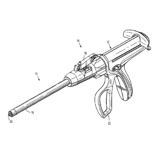
[0024] Figure 1 is a perspective view of a surgical stapling instrument
without a
loading unit connected thereto in accordance with the present disclosure;
[0025] Figure 1A is a perspective view of a loading unit in accordance
with the
present disclosure;
[0026] Figure 1B is a perspective view of a tool assembly of the
loading unit of
Figure 1A;
[0027] Figure 1C is a perspective view of a cartridge assembly of the
loading unit
of Figure 1A;
[0028] Figure 1D is an assembly view of the tool assembly of Figure 1B;
[0029] Figure 2 is a bottom perspective view of a portion of the tool
assembly of
Figure 1B;
[0030] Figure 3 is a perspective view of a portion of the tool assembly
of Figure
1B;
[0031] Figures 4 and 5 are transverse cross-sectional views of portions
of the tool
assembly of Figure 1B;
[0032] Figure 6 is a perspective view of a proximal portion of a
channel of the
tool assembly of Figure 1B;
[0033] Figure 7 is a perspective view of a distal portion of the
channel of the tool
assembly of Figure 1B;
6
CA 3050650 2019-07-26
[0034] Figure 8 is a transverse cross-sectional view of portion of the
tool
assembly of Figure 1B;
[0035] Figure 9 is a perspective view of the tool assembly of Figure 1B;
[0036] Figure 10 is a perspective view of a support plate of the tool
assembly of
Figure 1B;
[0037] Figure 11 is a perspective view of a distal portion of a
cartridge body of
the tool assembly of Figure 1B;
[0038] Figure 12 is a perspective view of a proximal portion of the
cartridge body
of the tool assembly of Figure 1B;
[0039] Figure 13 is a perspective view of a portion of a tool assembly
of the
present disclosure including another embodiment of a channel;
[0040] Figures 14 and 15 are perspective views of the channel of Figure
13;
[0041] Figures 16 and 17 are perspective views of different portions of
the
channel of Figure 13;
[0042] Figure 18 is a perspective view of a tool assembly of the present
disclosure including a lockout mechanism;
[0043] Figure 19 is an enlarged perspective view of the lockout
mechanism of the
present disclosure engaged with a portion of the tool assembly;
[0044] Figure 20 is a perspective assembly view of portions of the tool
assembly
includes the lockout assembly;
[0045] Figure 21 is a perspective view of the lockout mechanism engaged
with
the channel;
7
CA 3050650 2019-07-26
[0046] Figure 22 is a perspective assembly view of the lockout mechanism
and a
portion of the channel;
[0047] Figure 23 is an assembly view of the removable assembly of an
embodiment of the present disclosure;
[0048] Figure 24 is a perspective view of a latch of the lockout
mechanism of the
present disclosure;
[0049] Figure 25 is a perspective view of a sled of the present
disclosure;
[0050] Figure 26 is a top view of the cartridge assembly taken along
line 26-26 of
Figure 18 and illustrating the lockout mechanism, and the drive member and
sled in their
original positions;
[0051] Figure 27 is an enlarged view of the area indicated in Figure 26;
[0052] Figures 28-31 are top views of a portion of the cartridge
assembly
showing the drive member, sled, and latch in various positions;
[0053] Figures 32-35 are perspective views of a second embodiment of a
lockout
mechanism in accordance with an embodiment of the present disclosure.
DETAILED DESCRIPTION
[0054] Embodiments of the presently disclosed surgical instrument,
loading unit
and tool assembly for use therewith, are described in detail with reference to
the
drawings, wherein like reference numerals designate corresponding elements in
each of
the several views. As is common in the art, the term 'proximal" refers to that
part or
component closer to the user or operator, e.g., surgeon or physician, while
the term
"distal" refers to that part or component farther away from the user.
8
CA 3050650 2019-07-26
[0055] A surgical stapling instrument of the present disclosure is
indicated as
reference numeral 10 in Figure 1. Additionally, the depicted surgical
instrument fires
staples, but it may be adapted to fire any other suitable fastener such as
clips and two-part
fasteners. A loading unit for use with surgical instrument 10 is shown in the
accompanying figures and is indicated as reference number 500. A tool assembly
of the
loading unit 500 is shown in the accompanying figures and is indicated as
reference
number 1000.
[0056] Loading unit 500 is attachable to an elongated or endoscopic
portion 18 of
surgical instrument 10, e.g., to allow surgical instrument 10 to have greater
versatility.
Loading unit 500 of the present disclosure is configured for to be used more
than once.
In particular, the loading unit has a removable assembly 1600 that includes
the cartridge
assembly 1200. The cartridge assembly 1200 forms a part of the tool assembly
1000, and
the tool assembly 1000 forms a portion of the loading unit 500. The removable
assembly
is configured to be removed and replaced (e.g., after firing fasteners
therefrom).
Examples of loading units for use with a surgical stapling instrument are
disclosed in
commonly-owned United States Patent No. 5,752,644 to Bolanos et al. The
loading unit 500
shown includes a proximal body portion 502 that is attachable to an endoscopic
portion
or an elongated portion 18 of a surgical instrument 10 having a handle
assembly 12.
However, the features of the loading units 500 of the present disclosure,
including the
tool assembly 1000, can be incorporated in a surgical instrument in which does
not
include a detachable portion of the elongated portion of the instrument.
9
CA 3050650 2019-07-26
100571 Loading unit 500 includes a proximal body portion 502 and a tool
assembly 1000. Proximal body portion 502 defines a longitudinal axis "A-A,"
and is
releasably attachable to a distal end of elongated portion 18 of surgical
instrument 10.
Tool assembly 1000 includes a pair of jaw members including an anvil assembly
1100
and a cartridge assembly 1200. One jaw member is pivotal in relation to the
other to
enable the clamping of tissue between the jaw members. In the illustrated
embodiments,
cartridge assembly 1200 is pivotal in relation to anvil assembly 1100 and is
movable
between an open or unclamped position and a closed or approximated position.
However, the anvil assembly, or both the cartridge assembly and the anvil
assembly, can
be movable.
[0058] With reference to FIG. 1D, for example, anvil assembly 1100
includes an
anvil cover 1110 and an anvil plate 1112, which includes a plurality of staple
forming
depressions 1113. Anvil plate 1112 is secured to an underside of anvil cover
1110 and
defines a channel 1114 (see FIG. 8, for example) therebetween. When tool
assembly
1000 is in the approximated position, staple forming depressions 1113 are
positioned in
juxtaposed alignment with staple receiving slots of the cartridge assembly
1200.
[0059] The tool assembly includes a channel or carrier 1300 which
receives and
supports a cartridge assembly and a support plate 1500. The cartridge assembly
has a
cartridge body 1400. The cartridge body and support plate 1500 are attached to
the
channel or carrier 1300 by a snap-fit connection, as discussed below, a
detent, latch, or by
another type of connection. The cartridge assembly includes fasteners or
staples 1414.
Cartridge body 1400 defines a plurality of laterally spaced staple retention
slots 1410,
which are configured as openings in tissue contacting surface 1412 (see FIG.
11). Each
CA 3050650 2019-07-26
slot 1410 is configured to receive a fastener or staple 1414 therein.
Cartridge assembly
1200 also defines a plurality of cam wedge slots which accommodate staple
pushers 1416
and which are open on the bottom (i.e., away from tissue-contacting surface
1412) to
allow an actuation sled 1418 to pass longitudinally therethrough.
[0060] Further details of the various components of cartridge assembly
1200,
including the connection between its various components, and the removability
and
replaceability of cartridge body 1400 and support plate 1500 with respect to
channel
1300, are discussed below. Generally, the removable assembly 1600 includes
cartridge
assembly 1200 and support plate 1500. The removable assembly 1600 is removable
from .
channel 1300, e.g., after staples 1414 has been fired from cartridge body
1400. Another
removable assembly is capable of being loaded onto channel 1300, such that
surgical
instrument 10 can be actuated again to fire additional fasteners or staples
1414, for
instance.
[0061] Channel 1300, which may be machined (e.g., e.g., 1300a in FIGS.
13-17)
or made of sheet metal (e.g., 1300b in FIG. 9), includes one or a pair of
engagement
structures or proximal bosses 1310 (e.g., 1300b in FIG. 6), a pair of cut-outs
1320
disposed adjacent a distal end, a pair of distal slots 1330, a central slot
1340, a pair of
proximal holes 1350, and a ramped surface 1360. Proximal holes 1350 are
configured to
align with/mechanically engage a pair of corresponding holes 1120 (e.g., with
a pin or
protrusion extending through holes 1350 and holes 1120) on anvil cover 1110 to
facilitate
a pivotal relationship between anvil assembly 1100 and cartridge assembly
1200. It is
envisioned that engagement structures 1310 may be pins, protrusions, or
similar structure.
11
CA 3050650 2019-07-26
[0062] Cartridge body 1400 includes a central slot 1420, and rows of
staple
retention slots 1410 positioned on each side of slot 1420 (see FIG. 11). In
the illustrated
embodiment, three rows of retention slots 1410 are shown. More specifically,
cartridge
body 1400 is configured such that actuation sled 1418 can pass through the cam
wedge
slots and force staple pushers 1416 towards anvil plate 1112. The staples
1414, which
are supported on the pushers, are then forced out of their respective staple
retention slots
1410. Cartridge body 1400 also includes a pair of engagement structures or U-
shaped
recesses 1430 (which may, in other embodiments, be slots or openings) adjacent
its
proximal end, a pair of central bosses 1440, a pair of distal protrusions
1450, and a pair of
distal grooves 1460. Pairs of upper and lower mounting surfaces 1470, 1480,
respectively, are disposed adjacent a proximal end of cartridge body 1400, and
are
disposed adjacent respective upper and lower mounting slots 1472, 1482.
[0063] With particular reference to Figure 10, support plate 1500
includes a base
surface 1510, a longitudinal slot 1520 extending through base surface 1510, a
pair of
proximal fingers 1530 disposed and extending substantially perpendicularly
from a
proximal end of base surface 1510, a pair of interinediate fingers 1550
extending
substantially perpendicularly from a middle portion of base surface 1510, a
pair of
inwardly-extending fingers 1560 and outwardly-extending bosses 1570 disposed
adjacent
a distal end of base surface 1510, and a pair of proximal protrusions 1580
disposed
adjacent the proximal end of base surface 1510. Each proximal finger 1530
includes an
engagement structure or proximal-facing U-shaped recesses 1532, an upper
mounting
flange 1534, and a lower mounting flange 1536. As can be appreciated, support
plate
1500 helps maintain pushers 1416 in place with respect to cartridge body 1400.
12
CA 3050650 2019-07-26
Additionally, longitudinal slot 1520 allows a portion of a drive member to
pass through
the support plate 1500. The drive member may be a dynamic clamping member
1402.
The dynamic clamping member or drive member 1402 drives the actuation sled
1418
through the cartridge body 140. The central slot of the cartridge body, the
central slot of
the channel, and the longitudinal slot of the support plate are all configured
to align with
one another to allow the passage of the drive member.
[0064] In use, to connect cartridge body 1400 and support plate 1500,
cartridge
body 1400 and support plate 1500 are assembled or brought together such that
the
proximal-most end of cartridge is positioned between proximal fingers 1530 of
support
plate 1500 and in contact with base surface 1510 thereof. Support plate 1500
is then
longitudinally translated (e.g., slid distally) with respect to cartridge body
1400 such that
upper mounting flanges 1534 and lower mounting flanges 1536 engage upper
mounting
slots 1472 and lower mounting slots 1482, respectively. The longitudinal
translation
between cartridge body 1400 and support plate 1500 continues until a distal-
most end of
proximal fingers 1530 contact a respective vertical wall 1490 (FIG. 12) of
cartridge body
1400. At this stage, U-shaped recesses 1430 are laterally adjacent and aligned
with U-
shaped recesses 1532 (see FIG. 3), and continued proximal movement of
cartridge body
1400 with respect to support plate 1500 is prevented. Next, or concomitantly
with the
relative longitudinal translation between cartridge body 1400 and support
plate 1500, cut-
outs 1552 within intermediate fingers 1550 of support plate 1500 are
positioned around
central bosses 1440 of cartridge, and inwardly-extending fingers 1560 are
moved into
engagement with distal grooves 1460 of cartridge. Cartridge assembly 1200 and
support
plate 1500 comprise a removable assembly 1600, which is removable from and
13
CA 3050650 2019-07-26
replaceable onto channel 1300 by the user of the surgical instrument 10 and/or
loading
unit 500.
[0065] Removable assembly 1600 is insertable onto channel 1300 by
approximating removable assembly 1600 and channel 1300 such that proximal
bosses
1310 are positioned proximally of U-shaped recesses 1430 and 1532, and such
that distal
ends of distal slots 1330 are positioned proximally of proximal ends of
outwardly-
extending bosses 1570. Next, removable assembly 1600 is translated
longitudinally (e.g.,
proximally) with respect to channel 1300 such that outwardly-extending bosses
1570
translate proximally within distal slots 1330 until proximal bosses 1310
contact U-shaped
recesses 1430 and 1532. Next, or concomitantly with the relative longitudinal
translation
between removable assembly 1600 and channel 1300, cut-outs 1320 of channel
1300 are
moved into engagement with distal protrusions 1450 of cartridge body 1400.
Ramped
surface 1360 is engaged by the dynamic clamping member 1402 in order to move
the
anvil assembly 1100 and the cartridge assembly 1200 with respect to one
another. A
similar surface could be provided on the anvil assembly 1100, in other
embodiments. It
is envisioned that ramped surface 1360 may also facilitate the alignment
and/or
engagement between channel 1300 and support plate 1300 and/or cartridge body
1400.
[0066] Once assembled, a user is able to actuate movable handle 22 to
eject
staples 1414 from cartridge body 1400 and into tissue, as described below. It
is
envisioned that proximal protrusions 1580, which extend from base surface
1510, help
maintain actuation sled 1418 in its relative position with respect to support
plate 1500
. before actuation of instrument 10. That is, it is envisioned that actuation
sled 1418, or a
portion thereof, is positioned proximally of proximal protrusions 1580, and
that proximal
14
CA 3050650 2019-07-26
protrusions 1580 form a physically barrier to hinder any premature distal
advancement of
actuation sled 1418. Once a user intends to actuate instrument 10 and distally
advance
actuation sled 1418 beyond proximal protrusions 1580, the force used to
advance
actuation sled 1418 is sufficient to force a lower surface or portion of
actuation sled 1418
over proximal protrusions 1580.
[0067] After staples 1414 have been ejected from cartridge body 1400,
and a user
wishes to use the same instrument 10 to fire additional staples 1414 (or
another type of
fastener or knife), the user can remove the removable assembly 1600 by sliding
removable assembly 1600 distally with respect to channel 1300. Next, a user
removes
the removable assembly 1600 from the channel 1300. Another removable assembly
with
unfired staples can be loaded into the channel 1300. In other embodiments, a
cartridge
body of a cartridge assembly can be removable from a support plate after the
removable
assembly is removed from the channel 1300. The cartridge body is removed by
sliding
support plate 1500 proximally with respect to cartridge body 1400. Another
cartridge
body, if desired, may be coupled to the support plate and inserted into the
channel.
[00681 In certain embodiments, the removable assembly is part of a
loading unit
500 that is removably attached to the elongated portion of a surgical stapling
instrument,
such as elongated portion 18. This enables the user to choose a staple line
length that is
shorter or longer. It is also contemplated that the removable assembly can be
used with a
surgical instrument that does not have a loading unit that is removable and
instead has
jaws permanently attached to the elongated portion 18.
[00691 During operation of stapler 10, actuation of its movable handle
22 will fire
the staples. The handle assembly 12 has an elongate actuation shaft that is
translated
CA 3050650 2019-07-26
distally when the movable handle 22 is pivotally moved by the user. The
actuation shaft
of the handle assembly can include teeth that are engaged by the movable
handle 22, or
the handle assembly 12 can include a series of gears for moving the actuation
shaft.
Alternatively, the handle assembly can include a motorized driver for moving
the
actuation shaft, or the handle assembly can be attachable to a separate
motorized driver.
[0070] In certain embodiments, through successive strokes of the
movable
handle, a drive rod 30 (a distal portion of which is illustrated in Figures 1
and 27-31)) is
advanced distally, such that drive rod 30 pushes a portion of the drive
assembly (which
includes the dynamic clamping member 1402) to translate distally through
cartridge body
1400. (Further details of how actuation of movable handle 22 causes distal
advancement
of drive rod 30 are explained in U.S. Patent No. 6,953,139 to Milliman et al.
Distal movement of the drive assembly, and in
particular, the dynamic clamping member or drive member 1402, causes
approximation
of one jaw member with respect to the other. That is, an upper portion of the
dynamic
clamping member 1402 travels through the channel 1114 between the anvil plate
1112
and the anvil cover 1110, and a lower portion of the dynamic clamping member
1402
travels below the carrier 1300 of the cartridge assembly 1200, which causes
approximation of the anvil assembly 1100 and the cartridge assembly 1200 to
clamp
tissue therebetween. For example, the channel 1300 may have a lower surface
defining a
camming surface and the lower portion of the dynamic clamping member 1402
engages
the camming surface to pivot the cartridge assembly 1200 toward the anvil
assembly
1100.
16
CA 3050650 2019-07-26
[0071] Additionally, distal translation of the dynamic clamping member
1402
causes the actuation sled 1418 to move distally through cartridge body 1400,
which
causes cam wedges 1419 of actuation sled 1418 to sequentially engage pushers
1416 to
move pushers 1416 vertically within staple retention slots 1410 and eject
staples 1414
into staple forming depressions 1113 of anvil plate 1112. Subsequent to the
ejection of
staples 1414 from retention slots 1410 (and into tissue), a cutting edge of
the dynamic
clamping member 1402 severs the stapled tissue as the cutting edge travels
distally
through central slot 1420 of cartridge body 1400.
[0072] It is also envisioned, in further embodiments, that an end
effector or tool
assembly like the end effector or tool assembly 1000 is arranged for
articulating between
a first position where tool assembly 1000 is aligned with longitudinal axis "A-
A," and a
second position where tool assembly 1000 is disposed at an angle with respect
to
longitudinal axis "A-A." For example, the anvil assembly 110 may be pivotably
attached
to the proximal body portion 502 of' a loading unit 500, or pivotably attached
to the
elongated portion of the instrument. The loading unit includes one or more
cables or
linkages disposed in the proximal body portion 502 and attached at the tool
assembly
1000. When the cable or linkage is displaced, the tool assembly pivots and
articulates
with respect to the instrument. Further details of providing articulation are
described in
detail in commonly-owned U.S. Patent No. 6,953,139 to Milliman et al. Further,
the tool
assembly can be configured not to articulate.
[00731 Additionally, it is envisioned that instrument 10 is powered
by a power
source and/or motor. Further details of such a powered surgical instrument are
included
17
CA 3050650 2019-07-26
in U.S. Patent Publication No. 2008/0255607.
[0074] Further, and as illustrated in Figure 11, for example, the
present disclosure
includes a cartridge body 1400 having a stepped tissue-contacting surface
1412. In such
an embodiment, different sized staples 1414, or all the same sized staples,
may be used.
Further details of a staple cartridge having multiple staple sizes are
included in U.S.
Patent No. 7,407,075 to Holsten et al.
[00751 The present disclosure also relates to methods of using the
described
surgical instrument 10, loading unit 500, and tool assembly 100 to perform a
surgical
procedure and to methods of assembling the various components thereof, as
described
above.
100761 With reference to Figures 18-35, two embodiments of a lockout
mechanism 2000, 2000a of the present disclosure are shown. For each of these
embodiments, a surgical instrument having the lockout may have a channel,
removable
assembly, cartridge body, support plate, and the engagement structures
discussed above.
Furthermore, the present disclosure is directed to a removable assembly having
the
lockout, or a loading unit having the lockout.
[0077] With reference to Figures 18-31, the first embodiment of
lockout
mechanism 2000 includes a latch 2010 and a spring 2030, and is configured to
prevent re-
firing of cartridge body 1400 of removable assembly 1600, and also prevent
distal
translation of dynamic clamping member 1402 after an initial distal
translation of knife
and prior to another removable assembly 1600 being loaded onto channel 1300.
18
CA 3050650 2019-07-26
[0078] With particular reference to Figures 22 and 24, latch 2010
includes a body
2012 having an upper surface 2014 and a lower surface 2016, a lower protrusion
2018
depending downwardly from lower surface 2016, a spring stop 2019 extending
upwardly
from upper surface 2014, and a shaped surface 2020 on a first lateral side
2022. The
body 2012 also has a second lateral side 2024. The shaped surface 2020 has two
sides.
The first side 2020a is angled with respect to the central slot 1340 when the
latch 2010 is
in a blocking position in which the latch obstructs the passage of the dynamic
clamping
member 1402. The second side 2020b of the shaped surface 2020 extends
transversely to
the central slot 1340 when the latch is in the blocking position. (See Fig.
30).
[0079] Referring now to Figures 19-24, latch 2010 is mechanically
engaged with
channel 1300 so that the latch 2010 can pivot with respect to the channel
1300. In
particular, lower protrusion 2018 of latch 2010 (Figure 24) extends through an
opening
1380 (Figure 22) in channel 1300, such that latch 2010 is pivotable with
respect to
channel 1300. Lower protrusion 2018 is maintained in mechanical engagement
with
channel 1300 by a lock pin 2050 (Figure 22). Alternatively, the protrusion can
be
omitted and a separate pivot phi in engagement with the body 2012 and the
channel 1300
can be used.
[00801 With regard to Figures 21-22, spring 2030 includes a first leg
2032, a
second leg 2034, and an intermediate portion 2036 interconnecting first leg
2032 and
second leg 2034. First leg 2032 is in contact with a portion of channel 1300.
For
example, the channel 1300 may have a slot 1301, a notch, or some other feature
for
restricting the movement of the first leg 2032. Second leg 2034 is disposed in
contact
with spring stop 2018 of latch 2010. Intermediate portion 2036 is disposed
between first
19
CA 3050650 2019-07-26
leg 2032 and second leg 2034. For example, the spring may have a U-shaped
configuration (see Fig. 27), or some other shape, such as L-shaped.
[00811 Spring 2030 is in mechanical cooperation with a portion of the
cartridge
assembly 1200. The spring is configured to bias latch 2010 towards its
blocking position.
In the initial position of the dynamic clamping member 1402 and the sled 1418
(e.g.,
prior to distal advancement thereof to fire staples and incise tissue), a tail
portion 1417 of
sled 1418 (Figure 25) physically prevents the shaped surface 2020 of latch
2010 from
moving from its initial position into its blocking position, and thus allows
distal
translation of dynamic clamping member 1402 and sled 1418 (see Figures 26 and
27).
After translation of the dynamic clamping member and sled, the spring moves
the latch
2010 to the blocking position, where the shaped surface 2020 of latch 2010
obstructs the
central slot 1340 of channel 1300 and the longitudinal slot 1520 extending
through base
surface 1510 of support plate 1500 (see Figures 30 and 31), such that shaped
surface
2020 would block distal translation of dynamic clamping member 1402 when the
dynamic clamping member 1402 has been retracted after firing staples and
cutting tissue.
[0082] The latch 2010 is laterally movable from an initial position to a
blocking
position. The latch moves laterally, which enables the shaped surface of the
latch to
obstruct the slot and move away from a position that obstructs the slot of the
cartridge
assembly.
[0083] During retraction of the dynamic clamping member, the dynamic
clamping member slides along the shaped surface first side 2020a, keeping the
latch 2010
away from the dynamic clamping member and pivoting the latch against the bias
of the
spring. In the retracted position of the dynamic clamping member, it is
disposed
CA 3050650 2019-07-26
proximally of shaped surface 2020 and the sled 1418 and/or tail portion 1417
is not
abutting the shaped surface 2020. The latch 2010 pivots to the blocking
position, so that
the second side 2020b obstructs and/or prevents distal movement of the dynamic
clamping member.
[00841 During distal advancement of dynamic clamping member 1402 and
sled
1418, and after sled 1418 distally passes latch 2010 such that shaped surface
2020 is no
longer in contact with tail portion of sled 1418, dynamic clamping member 1402
abuts
the shaped surface 2020, which physically blocks latch 2010 from moving into
its
blocking position, and thus permits distal translation of dynamic clamping
member 1402
(see Figure 28).
[00851 When cartridge assembly1200 or removable assembly 1600 is
removed
from channel 1300, latch 2010 continues to block dynamic clamping member 1402
(see
Figure 31). When a new cartridge assembly1200 or removable assembly 1600 is
loaded
onto channel 1300, tail portion 1417 of the new sled 1418 engages shaped
surface first
side 2020a of latch 2010 and pivots latch 2010 away from its blocking
position. Without
a sled having the correct configuration, the latch remains in the blocking
position.
[0086] With reference to Figures 32-35, a second embodiment of lockout
mechanism 2000a is shown. A surgical instrument having the lockout may have a
channel, removable assembly, cartridge body, support plate, and the engagement
structures discussed above. Furthermore, the present disclosure is directed to
a
removable assembly having the lockout, or a loading unit having the lockout.
Lockout
mechanism 2000a includes a latch 2010a, and a spring. The spring is not shown
for
clarity, but may be as discussed above. Unlike the embodiment of lockout
mechanism
21
CA 3050650 2019-07-26
2000 discussed above, this embodiment of lockout mechanism 2000a does not
include a
lock pin 2050. Here, to maintain latch 2010a in engagement with channel 1300a,
lower
surface 201 6a of latch 2010a includes a locking member 2018a depending
therefrom.
[0087] In the illustrated embodiment, locking member 2018a includes a
pair of
parallel walls that are interconnected by a pair of arcuate walls. The opening
1380a of
channel 1300a includes similar, but slightly larger shape with respect to
locking member
2018a and also includes a circular recess 1381a, around which locking member
2018a
can rotate (see Figures 34 and 35).
[0088] To engage latch 2010a with channel 1300a, locking member 2018a
is
inserted through opening 1380a and latch 2010a is then rotated a predetermined
amount
(e.g., about 40 degrees to about 130 degrees) such that latch 2010a does not
fall through
opening 1380a of channel 1300a. The spring (not shown in this embodiment for
clarity)
may then be positioned between spring stop 2018a of latch 2010a and a portion
of
channel 1300a, as described above.
[0089] As can be appreciated, use of surgical instrument including the
second
embodiment of lockout mechanism 2000a is similar to, or that same as use of
the surgical
instrument including the first embodiment of lockout mechanism 2000, as
described
above.
[0090] While the above description contains many specifics, these
specifics
should not be construed as limitations on the scope of the present disclosure,
but merely
as illustrations of various embodiments thereof. Therefore, the above
description should
not be construed as limiting, but merely as exemplifications of various
embodiments.
22
CA 3050650 2019-07-26
,
Those skilled in the art will envision other modifications within the scope
and spirit of
the claims appended hereto.
23
CA 3050650 2019-07-26