Note: Descriptions are shown in the official language in which they were submitted.
CA 03051152 2019-07-19
WO 2018/145029 PCT/US2018/016904
1
WIRE-FORMED BIO-ABSORBABLE IMPLANTS AND METHODS FOR ASSEMBLY
CROSS-REFERENCE TO RELATED APPLICATIONS
[1] This application is based on, and claims the benefit of, United States
Provisional Patent
Application No. 62/454,202, filed February 3, 2017, which is hereby
incorporated herein by
reference in its entirety for all purposes.
FIELD OF THE INVENTION
[2] This document concerns an invention relating generally to bioresorbable
medical devices,
and more specifically, to bioresorbable implants such as stents that may
include one or more
wire-formed structures, may be modularized, and/or may be assembled without
the need for
manufacturing processes that could have undesirable effects on bioresorbable
metals, for
example processes that alter the mechanical and/or resorption properties of
bioresorbable
materials.
BACKGROUND OF THE INVENTION
[3] Traditional stents, which can be inserted into a cavity or duct (such
as a blood vessel) and
expanded to prevent or alleviate blockages, normally remain in the body
indefinitely unless
removed via a subsequent surgical procedure. In contrast, stents that are
biodegradable (also
referred to as bioabsorbable or bioresorbable, used interchangeably) can
disintegrate in the
body, and thus are normally not surgically removed at the end of their
functional life. To promote
bio-absorbability, such stents may include materials that may dissolve or
degrade in the body
over time, with nominal or no long-term negative effects on the patient.
Examples of such
materials include bioresorbable metals ('bio-metals'), such as magnesium,
zinc, and iron, and
alloys thereof. Use of bioresorbable metals can provide certain desirable
characteristics of
metallic compounds, such as structural support, while disintegrating safely so
as to not require
surgical intervention to remove, e.g. in the event of device failure. Because
surgical interventions
are not without risk of complications for patients, reducing the need for
unnecessary surgeries
CA 03051152 2019-07-19
WO 2018/145029 PCT/US2018/016904
2
(e.g. to remove an implanted stent) is preferable. Furthermore, in certain
cases a patient may be
subjected to additional interventions as a result of the presence of a
permanent implant, e.g. to
correct restenosis. Reducing interventions and surgeries can achieve
significant savings in cost
and time and enhance outcomes.
[4] However, although they can provide substantial benefits, devices such
as stents that are
made with bio-metals are engineered to have certain bio-mechanical and bio-
resorption
properties that should be preserved and maintained throughout the assembly and
implantation
process. Thus, there is a need to improved methods and apparatus for forming
bio-metal
implants such as stents."
SUMMARY OF INVENTION
[5] Exemplary versions of the present invention relate to implants such as
stents made with
wires having bio-absorbable metals ('bio-metals') such as magnesium and its
alloys. The ends of
the wires may be secured to each other mechanically (using, for example, a
securing mechanism
such as a joining cuff) in such a way so as not to affect the durability and
physical properties of
the end product. In various configurations, the stents or other implants may
include one or more
wires or wire-formed rings. Exemplary versions of the bio-metallic implants
(e.g. stents) may
include modules (such as the wire-formed rings) that can also be assembled
mechanically (using,
for example, a securing mechanism such as a bridging cuff). In other exemplary
versions, the
stents or other implants can include radiopaque ('R0') portions (such as the
joining and bridging
cuffs) configured to aid in the positioning and evaluation of exemplary stents
or implants in situ
by serving as visual indicators of alignment and expansion. In yet other
exemplary versions, the
wire-formed structure can be assembled or woven to form a net, using the
aforementioned
joining cuffs at multiple points of contact between the wires.
[6] In one embodiment, the invention provides a bio-metal implant including
a first
magnesium alloy wire. The first magnesium alloy wire is adjacent a second
magnesium alloy wire
at a first connection point, the first magnesium alloy wire coupled to the
second magnesium alloy
wire at the first connection point using a first joining cuff of a plurality
of joining cuffs, and the
CA 03051152 2019-07-19
WO 2018/145029 PCT/US2018/016904
3
first magnesium alloy wire and the second magnesium alloy wire being shaped to
form at least a
portion of the bio-metal implant.
[7] In another embodiment, the invention provides a bio-metal implant
including a plurality
of magnesium alloy wires formed into a tube. Each of the plurality of
magnesium alloy wires is
secured to two adjacent magnesium alloy wires of the plurality of magnesium
alloy wires by two
respective subsets of joining cuffs of a plurality of joining cuffs.
[8] In yet another embodiment, the invention provides a bio-metal implant
including a first
sinusoidal wire having ends secured together to form a first ring. The first
sinusoidal wire includes
a bio-metal and the ends of the first sinusoidal wire are secured together
without use of heat.
[8] In still another embodiment, the invention provides a method of
assembling a bio-metal
stent. The method includes joining a plurality of magnesium alloy wires into a
net by securing
each of the plurality of magnesium alloy wires to an adjacent magnesium alloy
wire of the
plurality of magnesium alloy wires using a subset of a plurality of joining
cuffs. The method also
includes forming the net into a tube shape by wrapping the net around a
mandrel. The method
further includes securing opposing edges of the net using a magnesium alloy
end wire by
attaching the magnesium alloy end wire to the opposing edges of the net.
[10] In yet another embodiment, the invention provides a method of
assembling a bio-metal
stent. The method includes providing a first sinusoidal wire having two ends
and including a bio-
metal; shaping the first sinusoidal wire into a first ring; and securing the
two ends of the first
sinusoidal wire together without use of heat.
[11] In still another embodiment, the invention provides a method of
implanting a stent in a
subject. The method includes providing a stent including a tubular structure
including a plurality
of wires connected by a plurality of joining cuffs, each of a subset of
joining cuffs of the plurality
of joining cuffs having a radiopaque marker. The method also includes placing
the stent within a
luminal space of the subject. The method further includes obtaining a first
image of the luminal
space showing first locations of the subset of joining cuffs having the
radiopaque markers. The
method also includes expanding the stent within the lumina! space. The method
further includes
obtaining a second image of the luminal space showing second locations of the
subset of joining
cuffs having the radiopaque markers, the second locations of at least two of
the subset of joining
CA 03051152 2019-07-19
WO 2018/145029 PCT/US2018/016904
4
cuffs having the radiopaque markers being further apart than the second
locations of the at least
two of the subset of joining cuffs having the radiopaque markers.
[12] Further advantages and features of the invention will be apparent from
the remainder of
this document in conjunction with the associated drawings.
DESCRIPTION OF THE DRAWINGS
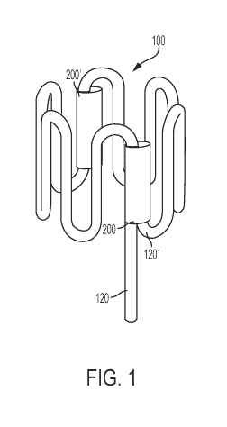
[13] FIG. 1 is an exemplary sinusoidal wire-formed ring, with ends secured
using an exemplary
circumferential joining cuff.
[14] FIG. 2 depicts a flat-view representation of the wire-formed ring
configuration of FIG. 1,
with the sinusoidal wire shown flattened into a two-dimensional plane.
[15] FIG. 3 provides a 'flat-view' representation of an alternative, six-
crown wire-formed
configuration with two wire tails secured to each other using a joining cuff.
[16] FIG. 4 depicts assembly of two adjacent (flattened) rings by insertion
of a wire tail of one
ring into a joining cuff of an adjacent ring.
[17] FIG. 5 shows the two flattened rings of FIG. 4 secured to each other
mechanically to
provide two adjoined rings.
[18] FIG. 6 is a perspective view of a four-ring, cylindrical stent, with
spines defined by joining
and/or bridging cuffs aligned such that long axes of the spines are aligned in
parallel in the stent.
The cuffs may include radiopaque materials such that they appear as the
'backbone' of the
elongated stent and can thus provide a visual indication of the orientation of
the stent using
various imaging techniques (such as fluoroscopic imaging).
[19] FIG. 7 is an image of an exemplary stent implanted in a blood vessel,
with radiopaque
cuffs visible via fluoroscopic imaging.
[20] FIG. 8 is an image of an exemplary stent that has been expanded, with
previously-parallel
radiopaque cuffs spread apart. The adjacent cuffs ('dual cuffs') in this
configuration secure the
second and third rings (the 'inner rings') of a four-ring stent.
[21] FIG. 9 is an image of an exemplary stent with wire tails functioning
as joining cuffs that
are received into cuffs to connect adjacent rings to one another.
CA 03051152 2019-07-19
WO 2018/145029 PCT/US2018/016904
[22] FIG. 10 represents an exemplary wire-forming process of using pins to
bend and shape
the wires as detailed in the text, during which bridging cuffs are slid into
place at pre-determined
locations on the wire.
[23] FIG. 11 depicts two parallel bridging cuffs on adjacent struts of an
exemplary flattened
wire-formed ring shown in a flat view.
[24] FIG. 12 is an image of an exemplary wire-formed, net-based stent
structure produced
according to the disclosed methods.
[25] FIG. 13 is a flat-view representation of a net for use as an implant
or for forming a net-
based stent such as that shown in FIG. 12.
[26] FIG. 14A shows use of a fixture for assembly of adjacent-parallel
(flattened) wires into a
net structure for use as an implant or for forming a net-based stent.
[27] FIG. 14B shows an inset from FIG. 14A showing how several wires are
threaded through
joining cuffs to form a portion of the net structure.
[28] FIGS. 15A-15C represents steps of an exemplary wire-forming process of
using a wire-
forming fixture to produce a net for use as an implant or for forming a net-
based stent such as
that shown in FIG. 12.
[29] FIG. 15D shows a single cuff with sealing material therein.
[30] FIG. 15E shows a cross-sectional view of the cuff of FIG. 15D.
DETAILED DESCRIPTION OF THE INVENTION
[31] In some embodiments, a wire having a sinusoidal shape may be formed
into a ring; one
or more such rings may be used (e.g. by joining the rings on their edges) to
form a ring-based
stent 300. In other embodiments, a plurality of wires may be joined by a
plurality of cuffs to form
a net 401, which may be used as an implant in the net form or the net may be
rolled into a tube
shape and secured to form a net-based stent 400.
[32] In accordance with this illustrative embodiment, the wires to produce
either embodiment
of the net 401 or stent 300, 400 may be formed from a bio-absorbable metal
component or alloy
(i.e. a 'bio-metal'). While the bio-absorbable metal components used to form
the wire in
CA 03051152 2019-07-19
WO 2018/145029 PCT/US2018/016904
6
accordance with the present teachings can be fabricated from a variety of
absorbable metallic
materials, in accordance with certain aspects, the metal components include
pure and alloyed
metals in order to achieve partial or full breakdown and absorption over a
period of time (e.g.
which can be about 1 month for plain, uncoated wire implant materials up to
several months, or
as much as a year for coated implants, depending on factors such as the
coating and site of
implant) sufficient for tissue healing. Illustrative metal components that may
be used in
accordance with the present teachings include, but are not limited to, pure
metals and alloys of
magnesium, zinc, and iron, and particularly alloys that are substantially free
of rare earth metals.
While incorporation of rare earth elements facilitates fabrication of bio-
metal devices, utilization
of alloys substantially free of rare earth metals minimizes the potential
adverse and toxicological
effects of these materials when implanted in the body. As used herein, in
certain embodiments
the term 'substantially free of rare earth metals' is intended to mean that
less than 500 ppm of
the metallic alloy includes rare earth metals. To this end, it should be
understood that the metallic
alloy components of the present teachings preferably have a high purity and
fine grain size in
order to achieve consistent strength and in vivo degradation rates in thin-
walled structures
regardless of the alloy that is used. As those of skill in the art will
understand and appreciate
herein, keeping the metallic alloy components substantially free of rare earth
metals may allow
the implant such as a net or stent to be naturally absorbed by the body while
having an additional
benefit that the structural integrity of the implant will not be negatively
impacted by the
inherently corrosive properties of the rare earth metals.
[33] For magnesium-based absorbable metals used in various embodiments of
the presently-
disclosed apparatus and methods, either pure magnesium or high-purity alloys
that contain one
or more of lithium, calcium, manganese, zinc, iron, aluminum, or combinations
thereof may be
used. In accordance with certain aspects of the present teachings, an alloy
wire may include more
than 50% by weight of one or more metals selected from: magnesium, iron, zinc,
calcium, and
manganese. In accordance with other embodiments in which alloys of magnesium
are used to
form an alloy wire, the magnesium alloy may contain between about 1% and about
25% by
weight lithium. Whatever specific components are used to form alloy wires, the
resulting alloy
wires should be formable into the various shapes as disclosed herein, for
example stents or other
CA 03051152 2019-07-19
WO 2018/145029 PCT/US2018/016904
7
implants that include wires formed into sinusoidal shapes, rings, and/or net
structures. In various
embodiments, the wire may have a thickness between about 10 microns and 300
microns, and
in particular embodiments the wire may have a thickness between about 50
microns and about
150 microns. In certain embodiments in which a stent is made for use in
coronary arteries, the
wire that is used may have a thickness of about 150 microns, and in other
embodiments in which
a stent is made for use in peripheral blood vessels, the wire that is used may
have a thickness of
about 150-200 microns.
[34] Various wire forming methods are generally known within the art, and
as such, the
fabrication methods envisioned by the present teachings are not intended to be
limited herein.
According to certain aspects herein, the wire can be processed by conventional
wire forming
methods that utilize a rotating pin table or a table of fixed pins to impart a
particular shape (e.g.
sinusoidal) on the wire. In addition, if desired, the final shaped wire, net,
and/or stent structure
may be electro-polished to remove surface contaminants, as well as to reduce
its final diameter.
Moreover, while not required herein, in accordance with certain aspects of the
present teachings,
it may also be beneficial to smelt the metallic alloys under vacuum and in
pyrolitic carbon molds
in order to minimize impurities. Finally, as discussed further below, a wire-
forming fixture may
be used to facilitate formation of a net. Additional wire compositions and
wire-forming methods
are disclosed in US Patent Appl. Publ. No. 2015/0272753, which is incorporated
herein by
reference in its entirety for all purposes.
[35] In various embodiments the methods and apparatus disclosed herein are
directed to
producing bioabsorbable wire-based implants such as stent structures using
magnesium-based
alloys (such as those discussed above) to take advantage of the
bioabsorbability of these highly
engineered alloy materials. However, it is important that the magnesium alloy
not be exposed to
manufacturing methodologies that will adversely affect the biomaterial
properties of the bio-
absorbable alloy as this can alter the properties of the alloy, for example
rendering it brittle or
imparting unwanted points of device failure. In general, excessive heat may
change factors such
as mechanical properties of the metal including grain size, microstructure,
ductility, and/or
strength, and the particular temperature and effects may depend on the metal
or alloy, the
thickness of material (e.g. wire), and/or the application.
CA 03051152 2019-07-19
WO 2018/145029 PCT/US2018/016904
8
[36] Although bio-metals can provide substantial benefits, stents made with
bio-metals pose
manufacturing challenges due in large part to their chemical compositions.
While stents made
from conventional, non-degradable metals can be subjected to well-
characterized, standard, and
wear-free processes, such as laser cutting and welding, these same processes
can adversely affect
bio-metals. For example, laser cutting of magnesium tubing that is extruded,
highly pure, and
free of rare earth elements can result in heat zones that may affect the
material composition of
the alloy, impacting the end-product's durability and physical properties.
Similar undesirable
outcomes can be experienced as a result of welding, which can heat the metals
to temperatures
of up to about 2000 C. For example, magnesium is a brittle element, and the
physical defects arising from spot welding can be amplified for magnesium
alloys, leading to
internal and surface cracking, and ultimately can affect the durability and
physical properties of
the desired product. Similarly, temperatures required for annealing of metals,
which are in a
range of 250 C-750 C, can also cause degradation of bio-metals. Consequently,
high-heat
manufacturing processes tend to compromise the integrity of bio-metallic
medical devices, in
part by affecting the grain size such that the requirement for small grain
size is no longer met, at
least for certain portions of the device.
[37] On the other hand, the presently-disclosed methods and apparatus
employ procedures
that function either at ambient temperatures or at moderately warm
temperatures that are
much lower than the temperatures cited above and as a result do not adversely
impact bio-
metals. For example, some polymers may need slightly elevated temperatures to
promote curing
of the polymers, however these temperatures are generally less than 100 C.
Similarly, in
embodiments in which joining cuffs are fitted onto wires using heat-shrinking,
the temperature
range for heat-shrinking for certain materials (e.g. PLA, PLGA, or PCL) are
less than 150 C, which
is sufficiently low that it will not have an adverse impact on the bio-metals.
[38] For conventional non-absorbable metal wire form based stents, this is
typically achieved
by spot welding adjacent rings through a laser or resistive welding process.
These processes,
however, are highly problematic for absorbable metal wire forms (such as
magnesium based alloy
systems); particularly as the magnesium surfaces rapidly form oxide layers
that in turn inhibit
strong metal to metal bonds from being formed. Welding of fine magnesium
structures is further
CA 03051152 2019-07-19
WO 2018/145029 PCT/US2018/016904
9
complicated by the material's intrinsic high thermal conductivity, such that
heat energy applied
to the local weld area is rapidly dissipated to the entire structure. In
addition, even if a mechanical
bond could be formed, the welding zone significantly changes the
microstructure of the
magnesium based alloy, thereby resulting in local embrittlement, undesirable
axial stiffness, and
non-uniform biodegradation rates.
[39] In various embodiments a polymer surface coating, selected from a
synthetic or natural
absorbable polymeric component, may be applied to the wire and/or to the net
401 or stent 300,
400 at any of the stages of assembly. The polymer surface coating may impart
advantages on the
coated material such as prolonging the absorption time (e.g. compared to wire
alone) and/or
reducing potential galvanic reactions, e.g. between the wire and bodily
fluids. The polymer
surface coating may include synthetic and natural polymers selected from, but
not limited to,
aliphatic and cyclic polyesters, polyanhydrides, polycarbonates, and
polypeptides such as
collagen, elastin or gelatin. In some embodiments, absorbable polymers that
can be used in
accordance with the present teachings include synthetic linear polyesters,
which have
mechanical properties and established clinical uses and biocompatibility, as
well as an ability to
be processed by melt (extrusion) or solvent (spray coating) methods. These
polymers may be
synthesized from a variety of monomers such as lactic acid (PLA), glycolic
acid (PGA),
caprolactone (PCL), diaxanone (PDO), and other close derivatives. These
monomers may also be
combined during polymerization to form co-polymers (e.g. PLGA is a copoplymer
of PLA and
PGA), with relative fractions controlled to influence properties such as
crystallinity, degradation
rate, and thermal stability. In certain embodiments, polymers based on two or
more monomer
types may be physically blended to achieve improved elasticity or altered
absorption rate. In
accordance with certain aspects of the present disclosure, the polymer surface
coating may
include a linear polyester high polymer selected from one or more of
polylactic acid, polyglycolic
acid, polydioxanone, polytrimethylenecarbonate and copolymers and blends
thereof. In various
embodiments, these polymer coatings may include (e.g. may be co-formulated
with), or be
further coated by, therapeutic agents, such as those discussed below.
[40] In certain embodiments, various therapeutic agents that may be used
(e.g. applied to the
implant or stent as a coating by coating, spraying, or other methods known to
those skilled in the
CA 03051152 2019-07-19
WO 2018/145029 PCT/US2018/016904
art) with the presently disclosed bio-metal implants including, but not
limited to, anti-restenotic
agents, anti-stenotic agents, antiproliferative agents, immunomodulators,
antithrombotics,
antioxidants, estrogen, growth factor inhibitors, antisense oligonucleotides,
collagen inhibitors,
chemotherapeutic agents, and combinations thereof. In addition, the
therapeutic agents can be
one or more drugs selected from one or more of paclitaxel and related taxanes,
rapamycin,
sirolimus, everolimus, tacrolimus, heparin, and benzalkonium heparinate.
[41] Ring-Based Bio-Metal Stents
[42] Referring to FIGS. 1 and 2, in some embodiments an exemplary wire-
formed ring 100 used
to make ring-based stents 300 extends from wire/ring tail 120 to end-tail
120'. The ring 100 in
FIG. 1 may be formed by bending a wire (e.g. a wire having a sinusoidal shape)
into a closed loop
and securing the loop in place using a joining cuff 200, where one or both of
a wire tail 120 at
one end of the wire and an end-tail 120' at the other end of the wire are
placed into the cuff 200.
A single ring may be used, or two or more such rings may be joined together,
to form a ring-based
stent 300.
[43] The wire used to form rings 100 may be provided with, for example, a
generally
'sinusoidal' shape, or it may be curved or wound in another oscillatory or
repetitive fashion. It is
noted that the use of the term sinusoidal is not intended to suggest that the
shape of the wire
must necessarily fit a sine function or any other geometric function or
equation, although the
wire may be provided with a regularity or other suitable pattern that may, for
example, be
interfittable with, or otherwise complementary to, adjacent rings in order to
enable
modularization of rings in a stent. For convenience, the term 'sinusoidal' in
this disclosure is used
to generally encompass all such various shapes and configurations. In general,
the wire includes
a plurality of bends or curves which permit a stent made from the wire to be
expanded into
position, for example within a patient's blood vessel.
[44] In one embodiment, the wire tail 120 may be mechanically secured to
end-tail 120' via a
joining cuff 200 to provide a 'ring' configuration for the sinusoidal wire.
The joining cuff 200,
which may be tubular or generally cylindrical with openings at opposing ends,
may receive the
wire tail 120 and end-tail 120' therein through the same (e.g. as depicted in
FIGS. 1 and 2), or
through different (opposing), ends. It is noted that the joining cuff 200 need
not have a tubular
CA 03051152 2019-07-19
WO 2018/145029 PCT/US2018/016904
11
'cuff-like' configuration, but rather could be replaced with any sort of
mechanically-adjoining
structure or connecting means that includes, without limitation, one or more
of a clip, fitting,
joint, coupler, splicer, link, adhesive, and/or other connector allowing for
the two ends of the
wires to be movably or immovably secured to each other. Advantageously, the
use of a
mechanical / adjoining mechanism / means maintains and preserves the
durability, integrity,
and/or reliability of devices made with bioresorbable metals in a way that
does not require use
of elevated heat or other manufacturing procedures that could degrade the bio-
metals.
[45] As will be further discussed below, the ring 100 could be sized or
configured to singularly
serve as a stent on its own, or it could be one unit / module in a
(modularized) stent that includes
two or more rings / units / modules. It is noted that the wire tail 120 may
extend out from the
joining cuff 200 (whereas the end-tail 120' need not extend out from the
joining cuff 200, or
otherwise may be shorter), allowing the longer wire tail 120 to be more easily
received in another
cuff of an adjacent ring in a stent (as further discussed below). Because ring
100 as depicted in
FIGS. 1 and 2 includes one wire tail 120 (which protrudes from the joining
cuff 200) and one
shorter end-tail 120' (which does not protrude from the joining cuff 200),
rather than two wire
tails 120, the ring 100 in FIG. 1 is well-suited to be an 'end piece' that is
situated at a terminus of
a stent. Ring 100 of FIG. 2 may be assembled into a stent alongside an
adjacent ring, the stent
extending generally in the direction of the ring tail 120 when secured to a
second ring 100. That
is, in this version, the wire-formed ring variation is an 'end-ring'
configuration with the end-tail
120' tucked into joining cuff 200. It is also noted that the ring 100 in FIGS.
1 and 2 also includes
an elongated bridging cuff 200', which will be further discussed below, and
which could optionally
be excluded in a stent formed of a singular ring 100 (i.e., a stent with only
one unit / module and
no adjacent units / modules) that includes two end-tails 120'. It is noted
that, in certain
configurations, joining cuffs 200 and bridging cuffs 200' may be similar (or
substantially identical)
structurally, but they differ functionally based on whether they secure ends
of a ring (joining cuffs
200) or secure two rings together (bridging cuffs 200'). In general the cuffs
200 join together two
portions of wire (from the same or different wires) at a connection point
between the wires, i.e.
a point where the wires are in proximity and possibly in contact and where the
cuff helps to
stabilize and maintain the wire(s) in this position.
CA 03051152 2019-07-19
WO 2018/145029 PCT/US2018/016904
12
[46] FIG. 3 provides another wire-formed ring variation with two ring tails
120 secured by a
joining cuff 200. Because there is no end-tail 120', this wire-formed ring is
well-suited for being
disposed between two other rings in a modularized stent. Thus, if the stent
were to have three
units, for example, the two rings between which the ring is disposed may be
'end rings' with one
ring tail 120 and one end-tail 120'. In the version depicted in FIG. 3, the
'wavy' wire includes six
'crowns' (the crowns being defined by the curved sections of the wire), each
crown having an
upper crown portion 102 and a lower crown portion 106 at opposing ends of a
strut 110. The
numbers 1 through 6, above the apices of each crown (adjacent to the upper
crown portions
102), represent the number of crowns in the ring. It is noted that any
suitable number of crowns
could be used to achieve various configurations for different applications,
and that adjacent
modules of a stent preferably have interfittable rings having the same number
of crowns, but all
the rings of a stent need not necessarily be identical. As shown in the
version of FIG. 3, two
aligned (i.e., substantially parallel) bridging cuffs 200' are positioned at
two adjacent struts 110.
[47] In certain embodiments the basic repeating unit of the sinusoidal wire
may be described,
for example as depicted in various figures, as having a substantially 'J'
shape formed by one of
the crown portions (102 or 106) in combination with a strut 110, with twelve
such units (pieces)
extending end-to-end to form the six crowns of FIG. 3, for example. The
configuration of the wire,
however, need not have such a repeating pattern, and each basic unit can be
different from
adjacent units to provide crowns that are not identical in shape but rather
that may vary in width,
height, pitch, angle, etc. Also, the struts 110, although shown as being
substantially linear, could
instead have a curved, wavy, sinusoidal, angled, or other shape in alternative
versions.
[48] FIG. 4 depicts assembly of two adjacent rings by inserting (e.g.
tucking or sliding) wire tails
120 into bridging cuffs 200' pre-loaded on an adjacent ring, to achieve the
two adjoined adjacent
rings depicted in FIG. 5. Although FIGS. 4 and 5 are depicted in flattened
views, the attachment
of wire tails into bridging cuffs 200' may be performed after the respective
wires have been
formed into three-dimensional rings, such as that shown in FIG. 6.
[49] FIG. 6 is a perspective view of a four-ring, sinusoidal wire-formed,
modularized cylindrical
stent 300 formed according to the disclosed procedures. The joining cuffs 200
and bridging cuffs
200' in the final assembled stent 300 may be aligned such that they form a
longitudinal 'spine'
CA 03051152 2019-07-19
WO 2018/145029 PCT/US2018/016904
13
along a portion (or substantially all) of the length of the stent 300, on one
or more sides thereof.
The stent 300 may include one or more additional longitudinal spines along a
portion of the
length of the stent 300 at various other positions. For example, a second
spine may be located
on an opposing side (i.e., approximately 180 degrees around the cylindrical
stent structure with
respect to the first spine). That is, parallel spines of cuffs (200 and 200')
may run along both sides
of the wire-formed ring-stent at an approximately 180 degree (or other amount)
separation.
[50] As suggested above, placement of the cuffs 200, 200' may create a
substantially (or
effectively) linear array, or spine, along both sides of the wire-formed ring
stent 300. Similar
arrays or spines of cuffs may also be present with the diamond-shaped cells of
the wire-formed
net stent 400, discussed further below. Using either type of stent (ring-based
or net-based), a
radiopaque material such as platinum-iridium may be included in a subset of
the cuffs (e.g. the
cuffs that are aligned into the 'spine' structure) so that the cuffs provide a
radiopaque reference
that allows the stent(s) to be visible under fluoroscopic imaging. In some
embodiments, a
radiopaque marker may be in the form of an extruded metal tubing (e.g. made of
a radiopaque
material such as platinum-iridium, or other material such as those disclosed
herein); the extruded
tubing may be incorporated into the cuff in various ways, including by sliding
the extruded tubing
over a polymer cuff material. In other embodiments, radiopaque materials may
be formed by
covalently binding iodine to polymers that are incorporated into a device.
[51] Radiopaque materials and elements may include: barium sulfate, bismuth
subcarbonate,
zirconium dioxide, cadmium, tungsten, gold, tantalum, bismuth, platinum,
iridium, and rhodium.
Radiopaque, physiologically-compatible materials may include metals and alloys
selected from
the Platinum Group metals, especially platinum, rhodium, palladium, rhenium,
as well as gold,
silver, and tantalum, and Group 6 metals (chromium, molybdenum, tungsten, and
seaborgium)
and alloys of these metals. These metals have significant radiopacity and in
their alloy forms may
be tailored to accomplish an appropriate blend of flexibility and stiffness,
and are also largely
biocompatible. One possible radiopaque material is a platinum/tungsten alloy,
e.g., 8% tungsten
and the remainder platinum. The particular form and choice of material used
for the implantable
frame will depend on the desired application. Therefore, if the cuffs are at
least partially
radiopaque, such that a significant portion of electromagnetic waves in
various imaging
CA 03051152 2019-07-19
WO 2018/145029 PCT/US2018/016904
14
modalities are unable to pass therethrough, the relative positioning and
alignment of cuffs 200
and 200' may provide useful information when imaging the stent. By contrast,
many bio-metals
(including those used in the wires) are radiolucent and thus are not visible
using standard X-ray
or fluoroscopic imaging methods. Addition of radiopaque material in one or
more cuffs (e.g. to a
linear spine of cuffs 200 and 200') in ring-based stent 300 or net-based stent
400, or formation
of two or more such spines of cuffs having radiopaque material (e.g. having
two spines separated
by 180 degrees when viewed in cross-section), creates both a method for simply
visualizing the
stents 300 and 400 under fluoroscopy as well as for accurately placing and
confirming expansion
of the stent in a blood vessel.
[52] Although the radiopaque cuffs (or other mechanical securing mechanism)
may be
arranged such that their long axes are parallel with each other to aid in
alignment, the cuffs need
not necessarily be arranged in a straight line (i.e. such that an imaginary
straight line could be
drawn through all the cuffs). Instead, in various embodiments the cuffs may be
arranged in any
configuration deemed suitable for the placement, identification, (re)location,
evaluation, or
other perception or manipulation of the stent in situ. For example, instead of
being arranged in
a straight row, the cuffs (200, 200') may be provided on opposing sides in an
alternating pattern,
for example, of adjacent rings of the stent 300. In ring-based stents 300, for
example as shown
in FIG. 6 and discussed further below, the cuffs may be slightly staggered
between adjacent rings
and thus would not necessarily be coaligned with the long axis of the stent
300 and/or would not
necessarily form a straight line.
[53] In various embodiments the mechanical securing mechanism (i.e. the
cuffs) need not be
elongated, and in other embodiments the mechanism may not have a well-defined
axis and/or
the long axes of the mechanism may not be aligned with the long axis of the
stent. Nevertheless,
the securing mechanisms may be positioned relative to each other to provide a
path or other
indication of the long axis of the stent, regardless of shape.
[54] FIG. 6 depicts a fully-assembled sinusoidal wave-form ring stent 300.
Wire-formed rings
100 are interconnected by securing each of the rings' tails 120 into pre-
positioned bridging cuffs
200' located on adjacent rings. In different configurations, wire tails 120
may be secured to the
bridging cuffs 200', for example using a biocompatible adhesive such as
cyanoacrylate injected
CA 03051152 2019-07-19
WO 2018/145029 PCT/US2018/016904
into the joining cuffs 200 and bridging cuffs 200'. Each wire-formed ring may
be independent
from any adjacent ring(s) to which it is connected, helping improve the hoop
strength of modular
stent 300. By providing a stent formed of independent stent-modules, failure
of one module (i.e.
a wire-formed ring) need not necessarily compromise other modules in the
stent.
[55] Cuffs 200, 200' may be pre-mounted to struts 110 of each ring during
the ring-forming
process for stent 300. Bridging cuffs 200' may be slid onto the wire at
various points in the
formation of the ring, including for example before or after bending of the
wire to form the
sinusoidal or other shapes. The cuffs 200, 200' on stent 300 may span a
portion (or substantially
all) of the distance between the upper 102 and lower 106 crowns. Ring tails
120 may be tucked /
inserted into joining cuff 200 to form a closed-ring with bridging cuffs 200'
pre-mounted on struts
110 at specified intervals. The placement of bridging cuff 200' may vary based
on, for example,
the number of crowns per ring and stent length. In the six-crown ring shown in
FIG. 3, for
example, bridging cuffs 200' may be slid into place at a spacing of 180 from
joining cuff 200. This
spacing can facilitate and/or help ensure symmetrical expansion of the stent.
[56] FIG. 7, for example, provides an image of two stents 300, 300'
obtained under
fluoroscopic imaging. Stent 300 (lower portion of FIG. 7) is in a pre-
expansion state, mounted to
a balloon delivery system that is also radiolucent (except for the two
radiopaque markers 20 that
are visible at either end of the stent as well as in the radiopaque cuffs 200
and 200' which make
up the linear spines). In this configuration, the linear arrays of radiopaque
cuffs (which form
spines) allow stent 300, which is mounted on the radiolucent balloon delivery
catheter, to be
visualized while it is rotated until the linear spines are aligned with the
walls of the blood vessels
10. This spine alignment method can facilitate and enhance precise placement
and expansion of
the stent when it is inflated. FIG. 7 also includes an image of an already-
expanded stent 300'
(upper portion of FIG. 7) aligned with another blood vessel, showing that the
spines are spaced
further apart than the spines of the pre-expansion stent 300.
[57] In the expanded stent 300' shown in FIG. 7, the second ring from the
bottom is pre-
mounted with two radiopaque bridging cuffs 200'. In different configurations,
each wire-formed
ring stent may comprise at least two rings with parallel cuffs 200' (i.e.
'parallel' in the sense that
the cuffs are separated on the ring and have axes that are approximately
aligned with one
CA 03051152 2019-07-19
WO 2018/145029 PCT/US2018/016904
16
another). In the version shown, the parallel cuffs 200' may serve both to
secure adjacent rings as
well as provide a fluoroscopic reference once the stent is expanded in the
blood vessel. During
the stent expansion procedure, the two parallel cuffs 200' separate indicating
that expansion has
occurred. This reference aids in delivery of the device.
[58] In some embodiments, cuffs may start in a parallel configuration prior
to expansion of the
stent but then are changed to a different configuration as a result of
expansion of the stent. For
example, FIG. 8 provides an image of (previously) parallel cuffs 200' after
expansion of stent 300
inside the blood vessel 10. The dotted lines and arrow heads depict proper
cell expansion; that
is, separation between the stent struts 110 such that struts 110 transition
from being
substantially parallel to one another to form a 'V' or 'L' shape. The term
'cell' here refers to the
area or space created between two struts 110 during the expansion of the wire-
formed ring 100.
Radiopaque cuffs 200/200' on each side of the rings can provide a visual cue
to help a clinician
ensure that each ring is well-expanded and apposed against the wall of blood
vessel 10. In such
embodiments, the ring tails serve as bridging connectors that are received in
bridging cuffs 200'
to bridge adjacent rings as seen in FIGS. 8 and 9.
[59] As discussed above, bridging cuffs 200' may be placed on a wire during
formation of a
sinusoidal ring, as shown in FIG. 10. Referring to the exemplary wire-forming
process of FIG. 10,
which may involve bending or twisting the wire around one or more fixed pins
or pegs (e.g. on a
pin board), bridging cuffs 200' may be slid into place at pre-determined
locations based on the
number of apices (e.g., number of upper and lower crown portions) during the
wire-forming
process to achieve a desired connection pattern. The placement of a third,
parallel joining cuff
on an adjacent strut (110) as depicted in FIG. 11, may correspond with the
number of rings to be
incorporated in the stent (such as the one in FIG. 6, discussed above). The
locations where cuffs
are slipped into place depends in part on the number of crowns or peaks per
ring, the number of
rings in the final stent, etc.
[60] Cuffs 200 and 200' can be made from a durable, a degradable, and/or a
combination of
durable, degradable, and, in certain embodiments, radiopaque material,
including but not limited
to platinum-iridium and polyimide. The joining cuffs with radiopaque elements
such as platinum-
iridium (or other materials as listed above) may be assembled in combination
with non-
CA 03051152 2019-07-19
WO 2018/145029 PCT/US2018/016904
17
absorbable polymers, such as polyimide, or with absorbable polymers, such as
poly-lactide (PLA),
poly(lactide-co-glycolide) (PLGA), or polylactone. The radiopaque material-
filled cuffs may also
be partially or fully insulated to prevent micro-galvanic corrosion and to
eliminate or significantly
reduce the galvanic potential of the differing elements.
[61]
Thus, in various embodiments, the cuffs of any of the disclosed embodiments
may include
one or more compounds from the following groups: polyphosphazenes,
polyanhydrides,
polyacetals, poly(ortho esters), polyphosphoesters, polycaprolactones,
polyurethanes,
polylactides, polycarbonates, and/or polyamides. The compounds may include one
or more of:
polyesters including poly-alpha hydroxy and poly-beta hydroxy polyesters,
polycaprolactone,
polyglycolic acid, polyether-esters, poly(p-dioxanone), polyoxaesters;
polyphosphazenes;
polyanhydrides; polycarbonates including polytrimethylene
carbonate and
poly(iminocarbonate); polyesteramides; polyurethanes; polyisocyantes;
polyphosphazines;
polyethers including polyglycols polyorthoesters; epoxy polymers including
polyethylene oxide;
polysaccharides including cellulose, chitin, dextran, starch, hydroxyethyl
starch, polygluconate,
hyaluronic acid; polyamides including polyamino acids, polyester-amides,
polyglutamic acid,
poly-lysine, gelatin, fibrin, fibrinogen, casein, collagen. The compounds may
also include one or
more FDA-approved materials including: polyglycolic acid (PGA), polylactic
acid (PLA), Polyglactin
910 (comprising a 9:1 ratio of glycolide per lactide unit, and known also as
VICRYLT.TM.),
polyglyconate (comprising a 9:1 ratio of glycolide per trimethylene carbonate
unit, and known
also as MAXON.TM.), and polydioxanone (PDS). Other examples of suitable
bioabsorbable
materials which may be used include: poly(glycolic acid), poly(lactic acid),
poly(epsilon-
caprolactone), poly(dimethyl glycolic acid), poly(hydroxy butyrate),
polydioxanone, copolymers
of polylactic acid and polyethyleneoxide, poly(lactide-co-glycolide),
poly(hydroxybutyrate-co-
valerate), poly(glycolic acid-co-trimethylene carbonate), poly(epsilon-
caprolactone-co-p-
dioxanone), poly-L-glutamic acid or poly-L-lysine, polyhydroxyvalerate,
poly(hydroxyalkanoates),
poly(3-hydroxybutyrate), poly(4-hydroxybutyrate),
po ly(3-hyd roxyva le rate), and
poly(caprolactone), or poly(valerolactone), poly(1,3-dioxan-2-one), poly(6,6-
dimethy1-1,4-
dioxan-2-one), poly(1,4-dioxepan-2-one), and poly(1,5-dioxepan-2-one). Yet
other examples of
polymers that can be used include: polyorthocarbonates, poly(amino acids) such
as polylysine,
CA 03051152 2019-07-19
WO 2018/145029 PCT/US2018/016904
18
and biodegradable polyphosphazenes such as poly(phenoxy-co-carboxylatophenoxy
phosphazene). In general, skilled artisans will understand that other
materials may be used to
make the cuffs; additional information regarding materials to be used for
medical implants may
be found in US Patent Appl. Publ. No. 2010/0262221, which is incorporated
herein by reference
in its entirety for all purposes.
[62] Net-Based Bio-Metal Stents
[63] In another embodiment of a bio-metal stent 400 (e.g. as shown in FIGS.
12 and 13), an
exemplary wire-formed net 401 may be produced by weaving wires through a
plurality of joining
cuffs 200 arranged in a pre-arranged pattern on a wire-forming fixture 500
(see FIG. 14A). The
wires used to form the net 401, for example, may be threaded along the length
of the wire-
forming fixture 500 into a woven pattern, as depicted in FIG. 14.
[64] FIG. 12 shows an image of a fully-assembled net stent 400 that has
been expanded using
a balloon. From FIG. 12 it can be seen that the expanded net stent 400
includes a number of
diamond-shaped repeating units, or cells 410. The cells 410 are formed when
wires 130 are
inserted into pre-positioned joining cuffs 200 and the net structure 401 is
wrapped around a
mandrel; the cylindrical, net-based stent 400 is completed and stabilized by
inserting end-wire
130' (sometimes referred to as a 'keystone' wire) into a particular subset of
joining cuffs 200'
along an edge of the net structure 401. Wire tails 120 at the end of the net
401 may be secured
with a biocompatible adhesive (e.g. cyanoacrylate) injected into the bridging
cuff 200'.
[65] To form a net 401 (which can subsequently be used to produce a net-based
stent 400), a
number of joining cuffs 200 are placed in an array of cuff spacers 502 on the
wire-forming fixture
500 (FIG. 14A). In some embodiments, the cuffs 200 may have an approximately
oval or oblong
cross-sectional shape which, when the cuffs 200 are placed into the cuff
spacers 502, may be
compressed into a rounded or approximately circular shape. Thus, following
insertion of one or
more wires into the cuffs 200 and subsequent removal of the cuffs 200 from the
cuff spacers 502,
the cuffs 200 may relax to their oblong shape and thereby provide a holding
force to help keep
the wires in the cuffs 200/keep the cuffs 200 from slipping out of position
relative to the wire(s).
[66] The fixture 500 depicted in FIG. 14A may be any suitable flat surface
to which are attached
a number of cuff spacers 502 in a desired array. The number and placement of
cuff spacers 502
CA 03051152 2019-07-19
WO 2018/145029 PCT/US2018/016904
19
may be determined by the dimensions and property of the final net 401 that is
produced. As
shown in FIG. 14A the cuff spacers 502 may be placed in rows that are slightly
offset from the
adjacent row(s) so that a particular wire may be threaded through a series of
cuffs in an
approximate zigzag pattern (e.g. see FIG. 14B, which is a close-up view of a
group of cuffs 200
that produce a single cell of the final net 401). A particular wire may be
associated with two
subsets of cuffs 200, a first subset through which it is coupled to a first
adjacent wire and a second
subset through which it is coupled to a second adjacent wire, where the
members of each subset
alternate along the particular wire. In certain embodiments, the stents 400
may have diameters
between 1 mm and 15 mm and lengths may range between 1 mm to 200 mm. In
various
embodiments, the dimensions of the edges of the nets 401 may vary from 1 mm
length/width to
500 mm length/width. In various embodiments, cuffs made of a durable material
such as
polyimide may have a wall thickness of approximately 0.002". In other
embodiments, a cuff
containing a radiopaque material such as platinum-iridium may have a wall
thickness ranging
from about 0.040" to about 0.032", depending on the particular application.
The final thickness
of the cuff that contains a radiopaque material may also be dependent on
factors such as ultimate
tensile and yield strength for the extruded metal tubing that is used (which
also provides an
indication of the malleability of the extruded tubing and its ability to be
attached, e.g. by
crimping, to the associated polymer cuff material). For polymer cuff
materials, other factors that
may influence the thickness of the cuff include: whether the cuff is made from
a durable (non-
absorbable) material vs. an absorbable material; availability of pre-made cuff
material of a given
thickness vs. ability to have cuff material made to a specified thickness;
and/or the wire size.
[67] The fixture 500 shown in FIG. 14A is not necessarily drawn to scale
(e.g. the distance
between adjacent rows of cuff connectors 502 may be proportionately much
greater than shown
in FIG. 14A) and may contain many more rows of cuff connectors 502, and each
row may contain
many more cuff connectors 502, than is shown. In addition, some of the cuffs
200 associated with
wires at the edges of the net 401 (e.g. shown on the left and right sides of
FIG. 14A) may have
only a single wire threaded through them; these cuffs will then have an
additional wire,
specifically the end-wire or keystone wire, threaded through them once the net
401 has been
rolled (e.g. around a mandrel) into a tube shape. The end-wire is threaded
through cuffs on
CA 03051152 2019-07-19
WO 2018/145029 PCT/US2018/016904
opposing edges of the rolled-up net 401 to hold the stent 400 together and
maintain the tube
shape. As noted previously, the cuffs 200 join together two portions of wire
(from the same or
different wires) at connection points between the wires, i.e. points where the
wires are in
proximity and possibly in contact and where the cuffs help to stabilize and
maintain the wire(s)
in certain positions.
[68] Thus, in certain embodiments the net 401 may be configured by weaving
wires through
joining cuffs 200, with the result that adjacent parallel wires are connected
to one another by a
series of joining cuffs 200, forming a plurality of repeating cells 410, as
depicted in FIG. 13. In
general, two adjacent wires 130 pass through each joining cuff 200 following
an arranged pattern
on the wire-forming fixture 500 (until end-tails 120' are inserted into final
common/ shared cuffs
and may or may not extend out from the joining cuff 200), allowing for
adjacent parallel wires
130 and end-tails 120' to form a plurality of cells 410, for which the
plurality of the cells make up
net like structure to later be formed into a stent 400. Although the basic
repeating cell 410
pattern shown in FIGS. 12-15 has a substantially 'diamond' shape, other
repeating patterns (e.g.
with one or more shapes including square, triangle, and/or rectangle) may be
formed by the
assembly of wires and cuffs 200, and in some embodiments not all of the basic
unit or cell shapes
may be the same but rather may vary in size, width, height, pitch, angle, etc.
[69] FIGS. 15A-15D show various steps of converting a net 401 to a net-
based stent 400. FIG.
15A shows a mandrel 600 around which a net 401 may be wrapped. Once the net
401 has been
rolled up (indicated by the curved arrows in FIG. 15B) and wrapped around the
mandrel 600, the
edges of the net 401 are joined together by weaving an end-wire 130' (or
keystone wire) through
the cuffs 200' at the edges of the net 401. FIG. 15C shows the end-wire 201
(wavy dashed line)
being woven through the cuffs 200' on the opposing edges of the net 401. Once
the end-wire
130' has passed through the edge joining cuffs 200', this stabilizes the net
401 into a tube shape
thereby creating the cylindrical net-shaped stent structure 400.
[70] After wires have been inserted into the joining cuffs 200, 200', the
cuffs may be joined
with an adhesive (i.e. filled with a sealing material 201 (FIG. 15E) such as
cyanoacrylate) and may
also be sealed along their long axes to prevent fluid infiltration into the
cuffs at the connection
points. For example, once the wires are mechanically secured within the cuff,
a sealing agent 201,
CA 03051152 2019-07-19
WO 2018/145029 PCT/US2018/016904
21
including but not limited to fillers, adhesives, glues, polymers, such as
epoxy, etc. may be added
inside the cuffs 200, 200' (FIGS. 15D, 15E). In various embodiments the cuffs
may be filled with
one or more medical grade adhesive selected from: acrylics (e.g.
cyanoacrylate), epoxies, and/or
polyurethanes. Sealing the cuffed areas prevents premature degradation and
thereby reduces
the risk of mechanical failure of the wire. In some embodiments a first
sealing agent 201 may be
a relatively low viscosity material that cures and sets quickly in order to
stabilize the wires within
the cuffs, followed by a second sealing agent such as a higher viscosity
material that completely
seals the wires within the cuffs against fluid penetration. In various
embodiments the cuffs may
be sealed before the net 401 is removed from the fixture 500 in order to
stabilize the wires and
cuffs before removing the net 401.
[71] In various embodiments a sealing material may be injected, e.g.
through a fine needle or
nozzle (e.g. attached to a pressure syringe), into the inside of the cuffs,
where the material will
cure and set. As discussed above, in certain embodiments a radiopaque material
such as
platinum-iridium may be added to the cuffs to allow the stents to be
visualized using X-ray
imaging technology and also to help confirm that the stent has been properly
expanded within a
patient's vessel or other lumina! space. In some embodiments the platinum-
iridium may be
inserted into the cuff and then a sealing material may be added to the cuff to
seal the cuff. In
particular embodiments, non-degradable materials may be selected for the cuff
and/or sealing
compound when the cuff contains radiopaque material, in order to encapsulate
the material and
prevent its release.
[72] As discussed above with regard to the ring-based stents 300, fewer
than all of the cuffs
200 may include radiopaque material. The cuffs 200 containing radiopaque
material may be
selected so that they to form particular patterns (e.g. such as the 'spines'
discussed above) which
aid in placement and confirming proper deployment of the net-based stent 400.
Given the
relatively large number of cuffs 200 in the net-based stent 400 structure,
determining which cuffs
200 to mark with radiopaque material is simplified since the stent 400
contains a regular array of
cuffs 200 to work with. As with the ring-based stents, multiple linear
arrangements or spines of
cuffs 200 may be marked with radiopaque material, for example two such spines
may be marked
CA 03051152 2019-07-19
WO 2018/145029 PCT/US2018/016904
22
so that the spines are on opposite sides of the cylindrical structure of the
stent 400, i.e. they may
be separated by 180 degrees when the stent 400 is viewed in cross-section.
[73] FIG. 15D shows a single joining cuff 200 having two wires running
through it and sealing
material 201 disposed inside. FIG. 15E, which corresponds to dashed line E-E'
in FIG. 15D, shows
a cross-sectional view through a sealed cuff 200. The wires 130 running
through the cuff 200 are
shown to be surrounded by the sealing material 201, which may include a
radiopaque material
and/or a sealant. In certain embodiments, the joining cuffs 200 may be made of
a non-absorbable
polymer such as polyimide or an absorbable polymer such as poly-lactide (PLA),
poly(lactide-co-
glycolide) (PLGA), or polylactone. In various embodiments the cuffs 200 may
have an inside
diameter of 0.20-0.50 mm, and in particular embodiments the inside diameter
may be 0.35 mm.
In other embodiments the cuffs may have a length ranging from 0.25-1.0 mm and
in particular
embodiments the length may be 0.75 mm. In certain embodiments, a 'cuff' may in
fact be two or
more segments of cuff material that are placed near each other to stabilize a
particular
connection point between two wires or segments of wire. In general the cuffs
need to be strong
enough to hold the net (or rings) together but sufficiently flexible and
resilient to permit the stent
to expand and to withstand movements associated with normal use during and
after being
implanted. Finally, it should be noted that the apparatus and methods for
producing the net-
based bio-metal stents can be used to produce the ring-based bio-metal stents,
and vice versa.
[74] Uses of Implants and Stents
[75] In various embodiments, the net 401 may be used in its flat form as a
bioabsorbable
implant or, as discussed further below, may be rolled and secured into a
tubular shape to be used
as a net-based stent 400. The flat net 401, the tubular net-based stent 400,
or the ring-based
stent 300 may be used within or outside the vascular system. In certain
embodiments, the tubular
ring-based stent 300 and/or net-based stent 400 may be placed inside a luminal
structure of a
subject including structures of the vascular, lymphatic, or gastrointestinal
systems as well as
various organ ducts. In particular embodiments, the flat net 401 and/or
tubular configuration
(i.e. stent 300 or stent 400) may be used a scaffold for soft tissue injury;
as a closure or fixation
device for soft tissue or bone; and/or as a filler. In those embodiments in
which the net 401 or
CA 03051152 2019-07-19
WO 2018/145029 PCT/US2018/016904
23
stent300/stent 400 is implanted into a non-vascular environment, the
particular therapeutic
agents and/or other coating materials may be changed to suit the particular
tissue environment.
[76] The present invention has been described in terms of one or more
preferred versions,
and it should be appreciated that many equivalents, alternatives, variations,
additions, and
modifications, aside from those expressly stated, and apart from combining the
different
features of the foregoing versions in varying ways, can be made and are within
the scope of the
invention. The true scope of the invention will be defined by the claims
included in any later-filed
utility patent application claiming priority from this provisional patent
application.