Note: Descriptions are shown in the official language in which they were submitted.
CA 03051286 2019-07-23
WO 2018/137038
PCT/CA2018/050093
WHEELCHAIR CASTER ASSEMBLY
WITH ANTI-FLUTTER FEATURE
CROSS-REFERENCE TO RELATED APPLICATION
[0001] The present application claims the priority of United States
Provisional
Patent Application Serial No. 62/450,742, filed on January 26, 2017 and
incorporated herein by reference.
TECHNICAL FIELD
[0002] The present application relates to wheelchairs and, more
particularly, to an
anti-flutter configuration for front caster assemblies of wheelchairs.
BACKGROUND OF THE ART
[0003] Wheelchairs are commonly provided with a pair of large rear drive
wheels,
with smaller front wheels, also known as casters or casters wheels. The caster
assemblies, in addition to enabling a rotation of the caster wheels, often
feature a
swivel joint to allow directional movement of the caster wheels, for the
direction of
the wheelchair to be controlled. As is conventional, the swivel joint of a
caster
assembly includes one or more bearings allowing a rotational movement of the
caster wheel about a generally upright axis. The bearing(s) provide a smooth
rotation of the caster wheel relative to a housing of the caster assembly.
[0004] Such caster assemblies may be known to experience flutter in some
instances. Indeed, when the wheelchair rolls along, the combination of
velocity,
friction and limited contact surface between caster wheel and ground, and
reduced
swivel resistance may cause flutter, i.e., an uncontrollable reciprocating
motion of
the caster wheel. Caster wheel flutter may cause a loss of directional control
for the
wheelchair, a premature wear of parts, and may be noisy, among other effects.
SUMMARY
[0005] It is an aim of the present disclosure to provide a caster wheel
assembly
that addresses issues associated with the prior art.
[0006] Therefore, in accordance with a first embodiment of the present
disclosure, there is provided a housing unit for a caster assembly comprising:
a
hollow housing body forming an inner cavity; a first bearing connected to the
hollow
1
CA 03051286 2019-07-23
WO 2018/137038
PCT/CA2018/050093
housing body, the first bearing defining a rotational axis through its center,
and
configured to rotatably support a first portion of a stem supporting a caster
for
rotation about the rotational axis; a support assembly connected to the hollow
housing body, the support assembly being spaced from the first bearing, the
support
assembly having bearing segments concurrently defining a plain bearing around
the
rotational axis, the plain bearing configured to rotatably support a second
portion of
the stem during rotation about the rotational axis; and a pressure-applying
component operatively mounted to the support assembly, the pressure-applying
component being selectively displaceable to displace the at least one of the
bearing
segments toward or away from the second portion of the stem, to increase or
decrease a pressure of the bearing segments on the second portion of the stem;
wherein the support assembly and the first bearing are configured to rotatably
support the stem of the caster to form a swivel joint.
[0007] Further in accordance with the first embodiment, a wedge is
positioned in
a gap between two of the bearing segments, a displacement of the pressure-
applying component causing a wedging effect of the wedge on the two of the
bearing segments.
[0008] Still further in accordance with the first embodiment, the wedge
and the
bearing segments are integrally formed into a monolithic piece.
[0009] Still further in accordance with the first embodiment, the bearing
segments
are connected to an annular support.
[0010] Still further in accordance with the first embodiment, the bearing
segments
and the annular support concurrently define a receptacle configured to receive
a
fastener or head of the stem.
[0011] Still further in accordance with the first embodimentõ further
comprising a
cap for being mounted to a top open end of the hollow housing body.
[0012] Still further in accordance with the first embodiment, an annular
body
projects downwardly from the cap and for being received in the inner cavity
via the
top open end.
[0013] Still further in accordance with the first embodiment, the cap
forms a
flange relative to the annular body.
[0014] Still further in accordance with the first embodiment, the cap has
a top
opening configured for receiving a top of the stem.
2
CA 03051286 2019-07-23
WO 2018/137038
PCT/CA2018/050093
[0015] Still further in accordance with the first embodiment, a pivot
connector is
on the hollow housing body adapted for pivoting engagement to a frame of a
wheelchair.
[0016] Still further in accordance with the first embodiment, a collar is
slidingly
engaged on the frame of the wheelchair, and an arm pivotally connected to the
collar and the housing body to convert a translation of the collar along the
frame to a
rotation of the housing body via the pivot connector.
[0017] Still further in accordance with the first embodiment, the
pressure-applying
component is a plunger translating relative to the support assembly to
displace the
at least one of the bearing segments.
[0018] Still further in accordance with the first embodiment, a direction
of
translation of the plunger is generally parallel to the rotational axis.
[0019] Still further in accordance with the first embodiment, the plunger
has a top
interface end accessible from a top surface of the support assembly.
[0020] Still further in accordance with the first embodiment, the plunger
is a screw
received in a threaded hole of the support assembly.
[0021] Still further in accordance with the first embodiment, the screw
is a set
screw having a socket accessible from a top surface of the support assembly.
[0022] Still further in accordance with the first embodiment, the support
assembly
is a monolithic component.
[0023] Still further in accordance with the first embodiment, the plain
bearing has
at least three of the bearing segments separated from one another by a gap.
[0024] In accordance with a second embodiment of the present disclosure,
there
is provided a system of a housing unit and caster assembly comprising: the
housing
unit as described above; and the caster assembly including the stem, a caster
and
means to rollingly support the caster at an end of the stem.
[0025] Still further in accordance with the second embodiment, the first
portion of
the stem and the second portion of the stem are cylindrical, the second
portion of
the stem having a smaller diameter than the first portion of the stem.
[0026] Still further in accordance with the second embodiment, the stem
has a
frusto-conical portion between the first portion and the second portion.
3
CA 03051286 2019-07-23
WO 2018/137038
PCT/CA2018/050093
[0027] Still further in accordance with the second embodiment, the stem
has an
open threaded top end, the caster assembly further comprising a bolt
operatively
engaged into the open threaded top end of the stem to hold the caster assembly
to
the housing unit.
[0028] Still further in accordance with the second embodiment, comprising
a
biasing unit is between the fastener and the support assembly.
[0029] Still further in accordance with the second embodiment, the means
is a
fork rollingly supporting the caster at the end of the stem.
DESCRIPTION OF THE DRAWINGS
[0030] Fig. 1 is a perspective view of a wheelchair featuring caster
assemblies in
accordance with the present disclosure;
[0031] Fig. 2 is a perspective view of a housing unit and stem of one of
caster
assemblies of Fig. 1;
[0032] Fig. 3 is an exploded view of the housing unit of Fig. 2;
[0033] Fig. 4 is an axially-sectioned perspective view of a support
assembly of
the housing unit of Fig. 2; and
[0034] Fig. 5 is an axial section view of one of caster assemblies of
Fig. 1.
DETAILED DESCRIPTION
[0035] Referring to the drawings and, more particularly, to Fig. 1, a
wheelchair
with an anti-flutter configuration is generally shown at 10. The wheelchair 10
has
rear drive wheels 11 and a frame 12 having a plurality of tubular frame
members, a
monocoque tubular frame, etc, the frame 12 forming the structure supporting a
plurality of components, such as rear wheel mounting brackets, a brake system,
foot
rests, etc. While not described in full detail as the anti-flutter
configuration may be
found in wheelchairs having other configurations, the frame 12 interfaces the
wheels
11 to a seat 13, a backrest 14, armrests 15 and/or caster assemblies 20, among
other components. For clarity, the rolling direction of the wheel 11 in a
forward
movement of the chair is illustrated by A.
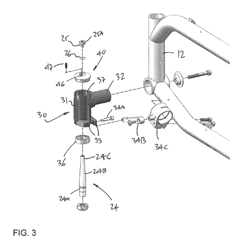
[0036] Referring concurrently to Figs. 2 and 3, one of the caster
assemblies 20 is
shown in greater detail. Although the wheelchair 10 may have a single one of
the
caster assemblies 20, according to an embodiment the wheelchair as two of the
4
CA 03051286 2019-07-23
WO 2018/137038
PCT/CA2018/050093
caster assemblies 20. The expression "caster assembly" is used throughout the
description for simplicity, but other expressions could be used to describe
the
assembly 20, such as front wheel assembly or system, etc. The caster
assemblies
20 may be configured for use on a left side or a right side of the wheelchair
10, but
for simplicity the description will apply to both the left-side assembly and
right-side
assembly, unless stated otherwise. For example, Fig. 2 and 3 shows a left-side
component, whereas Fig. 1 shows a right-side component, the components being
mirror images of one another. Moreover, although the caster assembly 20 is
shown
as used with the wheelchair 10, other apparatuses may use one or more of the
caster assemblies 20, such as strollers, carts, etc, especially wheeled
apparatuses
configured for being manually displaced.
[0037] The caster assembly 20 has a caster wheel 21, also known as a
caster,
roller, wheel, etc, as shown in Fig. 1. The caster wheel 21 has an axle 22
(also
known as axle bolt) by which it is rotatably supported by a fork 23, to roll.
Therefore,
a rotational axis of the axle 22 is generally parallel to the ground. The
expression
"generally parallel" entails that the rotational axis may not be perfectly
parallel to the
ground (e.g., the ground may not be straight), hence a 5-10 degree variation
may be
possible. The fork 23, also known as a yoke, may have a plurality of hole sets
to
adjust a vertical position of the caster wheel 21 relative to the fork 23. The
caster
wheel 21 may have different constructions, including a monolithic elastomeric
body
(e.g., rubber, plastomer), a tire or solid rubber wheel and rim/hub, a rubber
annular
interface or wheel on a rim/hub, etc. The caster wheel 21 may or may not have
a
bearing by which it is rotatably mounted to the axle 22, with bearings
including roller
bearings, ball bearings, among other possibilities. The axle 22 may be secured
to
the fork 23 in any appropriate manner, such as with nuts as shown in Fig. 1.
Although a dual-leg fork is shown at 23, it is contemplated to have the wheel
21
supported by a single leg (also known as a single-leg fork) or by other
arrangements.
[0038] A stem 24, also known as a shaft or bolt, projects upwardly from
the fork
23, and concurrently forms the swivel joint of the caster assembly 20 with a
housing
unit 30. In an embodiment, the axle 22 could be connected directly to a bottom
end
of the stem 24 as opposed to being connected to the fork 23. The figures show
the
fork 23 and the stem 24 being separate comments, with the fork 23 connectable
to a
bottom of the stem 24, for example by threading engagement. However, the fork
23
and the stem 24 may be integrally connected or fabricated, for instance in a
CA 03051286 2019-07-23
WO 2018/137038
PCT/CA2018/050093
monoblock construction. The caster wheel 21 and fork 23 may rotate about a
longitudinal axis of the stem 24, also known and referred to as the rotational
axis, in
a swivelling action of the caster wheel 21 to adjust a direction of the
wheelchair 10.
The longitudinal axis of the stem 24 may or may not be normal to the ground,
as an
adjustment of the orientation of the stem 24 may be possible, as explained
below.
The stem 24 may be an elongated cylinder, tubular or solid. However, other
shapes
are considered, for instance to lessen the weight of the caster assembly 20.
For
example, as shown in Fig. 5, the stem 24 may have a base portion 24A of
cylindrical
shape, a truncated cone portion 24B (a.k.a., frustoconical) and a tip portion
24C of
cylindrical shape, with the stem 24 being supported by bearings against the
base
portion 24A and the tip portion 24C. Such a configuration results in a lighter
stem
than one in which the base portion 24A would extend to the tip portion 24C
without
any reduction in diameter. The base portion 24A has a larger diameter than the
tip
portion 24C.
[0039] As shown in Figs. 3 and 5, the tip portion 24C of the stem 24 may
have an
open end (for example with threading as in Fig. 5, or with any other
attachment
arrangement) if not tubular from the base portion 24A to the tip portion 24C,
for a
fastener 25 to be engaged into the stem 24. The fastener 25 may be a bolt, for
example, but could also be a nut, a circlip, etc. The fastener 25 has a head
25A that
will ensure that the stem 24 remains connected to the housing unit 20, as
described
hereinafter. Moreover, a biasing element 26 may be inserted onto the body of
the
fastener 25, against an underside of the head 25A. The biasing element 26 may
be
a coil spring, a wave washer, a curved disc spring, among numerous possible
embodiments. Such a biasing element 26 could be a compression spring to pull
the
stem 24 upwardly along the longitudinal axis and hence remove any vertical
play
between the stem 24 and the housing unit 30. It is also considered to use the
fastener 25 to remove any vertical play, with the fastener 25 abutting against
any
part of the housing unit 20.
[0040] Referring to Figs. 2-4, the housing unit 30 is shown in greater
detail. The
housing unit 30 is the structural part of the caster assembly 20, in that it
supports the
caster wheel 21 by forming a swivel joint with the fork 23, while remaining
fixed to
the frame 12 of the wheelchair 10. The housing unit 30 has a hollow housing
body
31 accommodating part of the stem 24 and other operative components allowing
the
swivelling. In an embodiment, the housing unit 30 is part of the frame 12 of
the
wheelchair 10, i.e., it is one of the tubes constituting the wheelchair frame
12. A
6
CA 03051286 2019-07-23
WO 2018/137038
PCT/CA2018/050093
pivot connector 32 may project laterally from a wall of the housing body 31,
for being
received in a corresponding tube or bore in the frame 12, as shown in Fig. 1.
Therefore, unless anchored, the housing body 31 may rotate relative to the
frame
12, for an orientation of the caster assembly 20 to be adjustable relative to
the
ground. This is one possible connection configuration, as the caster assembly
20
may also be without such orientation adjustment mechanism as well. In order to
fix
the housing body 31 once suitably oriented, the orientation adjustment
mechanism
may also include a pair of blocks 33 projecting laterally from a wall of the
housing
body 31 and having a space or gap between them. A screw 34A or like rod is
retained at opposite ends by the blocks 33 and a portion thereof is exposed in
the
gap between the blocks 33. A torque arm 34B (a.k.a., link) has a first end
pivotally
connected to the screw 34A, and a second end pivotally connected to a collar
34C.
As the collar 34C slides along a portion of the frame 12, the orientation of
the
housing body 31 is adjusted. The collar 34C may be locked to the frame 12, to
block the rotation of the housing body 31 and hence fix the orientation of the
housing body 31. This adjustment may be performed to determine the angle
between the longitudinal axis of the stem 24 relative to the ground. In an
embodiment, this adjustment may be done to bring the rotational axis of the
stem 24
close to being normal to a plane upon which the wheelchair 10 lies with its
four
wheels.
[0041] Referring
to Figs. 3-5, the housing body 31 defines an inner cavity
receiving the operative components allowing the swivelling movement, and the
stem
24. The inner cavity may have a bottom counterbore 35 shaped to seatingly
receive
a bearing 36. According to an embodiment, the bearing 36 is force fitted or
press
fitted in the housing body 31 so as to be immovable. Other arrangements are
contemplated, such as using a circlip, or circlips, lock nuts, set screws,
etc, as
alternatives or additionally to the arrangement of bottom counterbore 35. The
housing body 31 may also have a top counterbore 37, shaped to seatingly
receive
an anti-flutter support assembly 40. Again, the support assembly 40 may also
be
force fitted or press fitted into the housing body 31 to come into abutment
with the
surfaces of the top counterbore 37. Other arrangements are contemplated, such
as
using a circlip, or circlips, lock nuts, set screws, etc. Both the bearing 36
and a plain
bearing portion of the support assembly 40, as described hereinafter, are
centered
on the longitudinal axis, as the bearing 36 and the support assembly 40
rotatably
support the stem 24 in forming a swivel joint.
7
CA 03051286 2019-07-23
WO 2018/137038
PCT/CA2018/050093
[0042] Referring to Figs. 3-5, the anti-flutter support assembly 40 is
shown in
greater details. With the bearing 36, the support assembly 40 rotatably
supports the
stem 24 to allow the swivel action of the caster wheel 21, and therefore acts
as a
bearing or as a support assembly. The support assembly 40 applies a variable
amount of friction to the stem 24, such that sufficient friction may be
selectively
applied to lessen or cancel flutter, while not excessively opposing forces
against the
swivel action of the caster wheel 21.
[0043] The support assembly 40 has a base 41. According to an embodiment,
the base 41 has an annular body (e.g., cylindrical body) that is sized to be
received
in the top end of the housing body 31, for instance with the annular base 41
seated
in the counterbore 37 if present. Therefore, the dimension of the annular base
41
may be selected as a function of the manner by which it be received in the
housing
body 31 (e.g., force fit, press fit), or tube frame if the housing 30 is a
tube of the
frame 12 as suggested above. A cap 42 may be at a top of the annular base 41
and
may optionally extend laterally or radially beyond the footprint of the
annular base
41. Therefore, as shown in Fig. 4, the cap 42 may abut against a top edge of
the
housing body 31, and prevent further inward progress of the support assembly
40
into the housing body 31, although this function may also be performed by the
surface of the counterbore 37 or like abutment (e.g., circlip used instead of
the
counterbore 37). As another possibility, the support assembly 40 is hung and
supported by its cap 42 with the base 41 entering the housing body 31, absent
a
counterbore 37. In another embodiment, the base 41 is force fitted or press
fitted
into the housing body 31 or frame tube, without any cap 42. Other
configurations
are considered for the base 41, including a base constituted of a plurality of
arcuate
segments, or a quasi-annular body with C-section, etc. The shape of the base
41 is
a function of the shape of the inner cavity of the housing body 31, which may
have
other shapes than a circle. The base 41 and the cap 42 concurrently define a
hollow center. However, the cap 42 may be without such a hollow center. An
annular support 43 is positioned in the hollow center, and defines a central
bore of
the support assembly 40. According to an embodiment the annular support 43
projects downwardly from the cap 42, and into the inner cavity of the housing
body
31. Referring to Figs. 4 and 5, bearing segments 44 project radially inwardly
from
the annular support 43, and each have a bearing surface 44A for sliding
contact with
the stem 24. The bearing surfaces 44A concurrently define a diametrical
surface
against which the stem 24 slides during rotation, i.e., a plain bearing. As
shown in
8
CA 03051286 2019-07-23
WO 2018/137038
PCT/CA2018/050093
Fig. 5, the arrangement of the annular support 43 and of the bearing segments
44
defines a receptacle for receiving the head 25A of the fastener 25, with the
biasing
element 26 applying a tension force. The cooperation between the fastener 25
and
the support assembly 40 ensures that the stem 24 remains captive in the
housing
unit 30. The support assembly 40 may have two or more of the bearing segments
44, although in an embodiment there are at least three of the bearing segments
44.
[0044] The support assembly 40 may cooperated with a pressure-applying
component, that is operatively mounted to the support assembly 40. In an
embodiment, the pressure-applying component is an integral part of the support
assembly 40. According to an embodiment, the pressure-applying component
applies a pressure on a wedge 45. In Fig. 4, the wedge 45 is in a gap between
a
pair of the bearing segments 44. The wedge 45 is a projection from the annular
support 43, and is therefore cantilevered. A bore 46 is defined in the annular
support 43, opening to the top surface of the cap 42. The bore 46 is threaded,
such
that a set screw 47 of the pressure-applying component may be operatively
received
therein. A rotation of the set screw 47 results in its translational
displacement along
the bore 46. The bore 46 is positioned so as to be adjacent to the wedge 45.
Therefore, a downward movement of the set screw 47 - as shown as A - results
in a
pressure applied to the wedge 45, causing a radially inward movement of the
wedge
45 - as shown as R, by way of elastic deformation for example. Consequently,
the
wedge 45 increases the gap between the pair of the bearing segments 44,
resulting
in an increase in a diameter formed concurrently by the bearing surfaces 44A.
Inversely, an upward movement of the set screw 47 - in a direction opposite to
A ¨
causes a radially outward movement of the wedge 45 ¨ in a direction opposite
to R -
, due to the wedge's 45 tendency to return to an unloaded position (in which
the
wedge 45 applies little or no pressure on the bearing segment(s) 44, resulting
in
minimum diameter of the plain bearing of bearing segments 44). As a result of
the
upward movement of the set screw 47, the wedge 45 decreases the gap between
the pair of the bearing segments 44, resulting in a decrease in a diameter
formed
concurrently by the bearing surfaces 44A, and therefore in an increase
pressure and
friction of the bearing surfaces 44A on the stem 24. The position of the set
screw 47
along the bore 46 may be manually adjusted until a desired freedom of swivel
is
reached for the caster wheel 21.
[0045] It is contemplated to provide variations to the arrangement
described
above. According to an embodiment, the pressure-applying component applies a
9
CA 03051286 2019-07-23
WO 2018/137038
PCT/CA2018/050093
pressure on a single one of the bearing segments 44, instead of applying
pressure
on a wedge between a pair of bearing segments 44. In such a case, the pressure-
applying component may be a plunger (such as the set screw 47) directly
contacting
a radially outward surface of one of the bearing segments 44. While the
expression
"plunger" is used, other words could also be used to define this embodiment of
the
pressure-applying component, such as a driver, a pin, a shaft. As alternatives
to a
plunger, the pressure-applying component may be a screwing ring, a detent,
etc,
among other possibilities. According to another embodiment, a plunger such as
a
set screw with or without a contact pad applies a pressure directly against
the stem
24. According to an embodiment, aside from the set screw 47, the support
assembly 40 is made of a monolithic integral construction, i.e., a single
piece of a
single material. For example, the support assembly 40 may consist of a
monolithic
block of a wear-resistant polymer, such as iglide , that may be molded or
machined,
although other materials are considered, such as PTFE, etc. However, the
support
assembly 40 may also be made of a composition of different pieces as well. It
is
desired that the wedge 45 deform in elastic deformation as it is displaced by
the set
screw 47. Likewise, the movement of the bearing segment(s) 44 as pressed by
the
pressure-applying component may be an elastic deformation. It is observed that
a
direction of translation of the set screw 47 is generally parallel to a
longitudinal axis
of the stem 24. In the case of a set screw configuration for the plunger, the
direction
of translation is parallel to the rotational axis of the set screw 47. The
expression
"generally parallel" entails that the translational direction may not be
perfectly
parallel to the longitudinal axis, hence a 5-10 degree variation (if not more)
may be
possible. This results in the plunger having its top interface end (e.g., the
set screw
47 having its hexagonal socket) accessible from a top of the support assembly
40,
and therefore from a top of the caster assembly 20, which may be ergonomically
convenient. In an embodiment, the hexagonal socket is a 1.5 mm or a 2.0 mm
socket. Alternatively, the set screw 47 could be oriented generally
transversely to
the rotational axis of the stem 24, among other possibilities. It is also
considered to
use alternative plungers to the set screw 47, such as a slidable pin, for
example.
Other arrangements are considered, such as a collar mounted to the bearing
segments 44 and movable along direction A to cause radial displacement of the
bearing segments 44, to increase or decrease the pressure applied on the stem
24.
[0046] In order to assemble and remove the flutter with the caster
assembly 20,
the stem 24 supporting the caster wheel 21 is firstly inserted in the housing
unit 30,
CA 03051286 2019-07-23
WO 2018/137038
PCT/CA2018/050093
in the manner shown in Fig. 5, but without the fastener 25 to allow the stem
24 to be
inserted. The fastener 25 is then used to hold the stem 24 captive in the
housing
unit 30. If a biasing element 26 is used, it is sandwiched between the
fastener 25
and the bearing segments 44, to remove any vertical play (i.e., along the
longitudinal
axis). At this point, the freedom of swivel movement may be assessed. If the
caster
wheel 21 is determined to be too loose in swivelling, the pressure-applying
component may be adjusted for the bearing segments 44 to apply more friction
on
the stem 24. According to an embodiment, the pressure is applied by displacing
the
set screw 47 upwardly, conventionally by counterclockwise rotation. This may
be
done incrementally, until a suitable freedom of swivel is reached. To the
contrary, if
the caster wheel 21 is determined to be too restrained in swivelling, the
pressure-
applying component may be adjusted for the bearing segments 44 to apply less
friction on the stem 24. According to an embodiment, the pressure is released
by
displacing the set screw 47 downwardly, conventionally by clockwise rotation.
[0047] While a specific configuration of the support assembly 40 is
detailed
above, other configurations are considered. In a non-exhaustively list of
exemplary
configurations, the annular support 43 is directly mounted to the housing body
31,
the bearing segments 44 project from the base 41 or from the cap 42, etc.
11