Note: Descriptions are shown in the official language in which they were submitted.
CA 03051522 2019-07-24
W02018/178252
PCT/EP2018/058112
1
ELECTROSURGICAL ENERGY CONVEYING STRUCTURE
AND ELECTROSURGICAL DEVICE INCORPORATING THE SAME
FIELD OF THE INVENTION
The invention relates to an electrosurgical device for
use in minimally invasive procedures, e.g. endoscopy,
gastroscopy, bronchoscopy, laparoscopy, etc. In particular,
the invention relates to an energy conveying structure (e.g.
waveguide or cable) for carrying radiofrequency (RF) and/or
microwave energy from an electrosurgical generator along an
instrument cable that is insertable into a patient's body to
reach a treatment site. The invention may find particular use
in natural orifice transluminal endoscopic surgery (NOTES).
BACKGROUND TO THE INVENTION
Conventional surgical scoping devices comprise an
insertion tube that can be manoeuvred to a treatment site in a
patient's body via a catheter or natural orifice. The
insertion tube conveys components to the treatment site. In
some examples, the insertion tube comprises an observation
channel for conveying an illumination signal and returning an
imaging signal, and a separate instrument channel for
conveying an instrument for manipulating or otherwise treating
tissue at the treatment site. It can be desirable to have
real-time vision of the treatment site during treatment.
Electrosurgical instruments are instruments that are used
to deliver radiofrequency and/or microwave frequency energy to
biological tissue, for purposes such as cutting biological
tissue or coagulating blood. Radiofrequency and/or microwave
frequency energy is typically supplied to the electrosurgical
instrument using a cable. Conventional cables used for this
purpose have a coaxial transmission line structure comprising
a solid or multi-wire cylindrical inner conductor, a tubular
CA 03051522 2019-07-24
WO 2018/178252
PCT/EP2018/058112
2
layer of dielectric material around the inner conductor, and a
tubular outer conductor around the dielectric material.
When operating many electrosurgical instruments it is
common to need to provide additional supplies or components
(e.g. control means) to the electrosurgical instrument, such
as a liquid or gas feed, liquids or gases, or guide- or pull-
wires for manipulating (for example opening/closing, rotating
or extending/ retracting) part(s) of the electrosurgical
instrument.
In order to provide these additional supplies or
components to the electrosurgical instrument, additional
structures have been provided together with the conventional
cable, such as additional tubes adjacent to the conventional
cable. For example, it is known to provide an additional tube
housing a pull-wire for the electrosurgical instrument
alongside the conventional cable, and to house the
conventional cable and the tube housing the pull-wire within a
single protective jacket/casing.
Typically, the diameter of an instrument channel of a
surgical scoping device (e.g. endoscope or laparoscope) is
less than 3 mm, e.g. 2.8 mm. It is an ongoing challenge to
provide both sufficient power and the additional supplies or
components mentioned above in a compact enough form to fit
within an instrument channel whilst maintaining flexibility
and restricting power loss to acceptable (i.e. safe) levels.
SUMMARY OF THE INVENTION
At its most general, the present invention proposes the
combined delivery of RF or microwave electromagnetic energy
for tissue treatment (e.g. ablation, coagulation or cutting)
and optical radiation within a common structure that may form
an instrument cable of a surgical scoping device. The
advantages of the invention are threefold. Firstly, the
common structure provides a more compact arrangement for
CA 03051522 2019-07-24
WO 2018/178252
PCT/EP2018/058112
3
systems in which it is desirable to visualise electrosurgical
treatment. Secondly, it can enable functionality associated
with optical radiation (e.g. imaging or other forms of
sensing) to be available on surgical scoping devices without a
dedicated observation channel. Thirdly, it can enable the
provision of a new family of ultra-small diameter surgical
scoping devices which opens up the possibility of
electrosurgical treatment in regions that are inaccessible to
conventional instruments.
In one example, the common structure may be compact to
enable visually-assisted ablation of biological tissue to
occur in regions that are inaccessible to conventional
surgical scoping devices. However, the use of optical
radiation discussed herein need not be confined to providing
images of the treatment site. The optical radiation can be
used to probe the treatment site to measure properties thereof
for diagnostic purposes. For example, the invention may be
used to provide laser scattering measurements/spectroscopy, UV
reflectometry/scattering measurements, etc.
The term "optical radiation" used herein may relate to
electromagnetic radiation having a free space wavelength in
the range 100 nm to 1 mm. In some embodiments, the optical
radiation is in the visible spectrum, where it can be used to
illuminate the treatment site and provide visual assistance
for an operator. The optical radiation may be broadband, e.g.
from a white light source. In other examples, the optical
radiation may be narrow band or may have specific wavelengths
for detecting or probing certain tissue characteristics. For
example, green and blue wavelengths may be selectively applied
to the tissue for inspection during an endoscopy procedure.
Wavelengths of 415 nm and 540 nm may be preferred.
Visualisation of the different layers is possible due to the
difference in penetration depth of each wavelengths. 415nm
light is used to show the capillaries in the mucosa whilst 540
nm allows visualisation of the blood vessels in deeper layers.
CA 03051522 2019-07-24
WO 2018/178252
PCT/EP2018/058112
4
In some examples, the common structure may further
include means for transmitting ultrasonic signals, e.g. from a
distal instrument tip to one or more ultrasonic sensors in a
handpiece. The common structure may thus be used to form an
electrosurgical device capable of delivering any or all of
RF/microwave EM energy, optical radiation and ultrasonic
signals to a treatment site along an instrument cable of a
surgical scoping device.
According to the invention, there is provided an energy
conveying structure for invasive electrosurgery, the energy
conveying structure comprising a coaxial layered structure
having: an inner conductive layer; an outer conductive layer
formed coaxially with the inner conductive layer; and a
dielectric layer separating the inner conductive layer and the
outer conductive layer, wherein the inner conductive layer,
the outer conductive layer and the dielectric layer form a
coaxial transmission line for conveying radiofrequency (RF)
and/or microwave electromagnetic (EM) energy, wherein the
inner conductive layer is hollow to form a longitudinal
passage, and wherein the energy conveying structure further
comprises an optical channel for conveying optical radiation,
the optical channel being located in the longitudinal passage.
The energy conveying structure thus resembles a hollow coaxial
transmission line with an optical channel formed within it.
In this example, the optical channel lies within a passage
that is formed within the inner conductive layer. In other
examples, the optical channel may lie within a passage formed
within other layers of the coaxial layered structure, e.g. the
dielectric material or the outer conductor layer. The optical
channel may be annular. The optical channel may be the
dielectric material of the coaxial layered structure.
With the arrangement defined above, the energy conveying
structure can deliver RF/microwave energy for treatment (e.g.
ablation) and optical radiation for sensing or visualising the
treatment site in a particularly compact manner. The coaxial
CA 03051522 2019-07-24
WO 2018/178252
PCT/EP2018/058112
layered structure may comprise an innermost insulating layer
between the inner conductive layer and the optical channel.
The innermost insulating layer may prevent interference
between the optical channel and the coaxial transmission line.
5 In this
specification "microwave" may be used broadly to
indicate a frequency range of 400 MHz to 100 GHz, but
preferably the range 1 GHz to 60 GHz. Specific frequencies
that have been considered are: 915 MHz, 2.45 GHz, 3.3 GHz, 5.8
GHz, 10 GHz, 14.5 GHz and 24 GHz. In contrast, this
specification uses "radiofrequency" or "RF" to indicate a
frequency range that is at least three orders of magnitude
lower, e.g. up to 300 MHz, preferably 10 kHz to 1 MHz.
References herein to a "conductor" or "conductive"
material herein are to be interpreted as meaning electrically
conductive unless the context makes clear that another meaning
is intended.
The energy conveying structure may be dimensioned to be
insertable in a flexible insertion tube of an invasive
surgical scoping device. For example, it may have a maximum
outer diameter equal to or less than 3.5 mm, preferably equal
to or less than 2.8 mm. Herein, the term "surgical scoping
device" may be understood as a generic term that refers to a
class of devices used in minimally invasive procedures, where
the device typically include a rigid or flexible instrument
cord that is insertable into a patient's body. The instrument
cord is used to provide access to a treatment site for a
variety of reasons, e.g. to perform surgical procedures,
perform visual inspection or capture images, take biopsies,
etc. Examples of a surgical scoping device include an
endoscope, a bronchoscope, a laparoscope and the like.
The energy conveying structure may itself form an
instrument cable for a surgical scoping device. In this
example, the coaxial layered structure may comprise a
protective sheath on the outer surface of the outer conductive
CA 03051522 2019-07-24
WO 2018/178252
PCT/EP2018/058112
6
layer. The protective sheath may be made from biocompatible
material or may have a biocompatible coating.
The protective sheath may contribute to steerability of
the structure. For example, the protective sheath may
comprise a distal portion and a proximal portion, wherein the
proximal portion is configured to have greater rigidity than
the distal portion. The proximal portion may comprises an
additional stiffening layer or braiding to inhibit flexing or
deformation.
The optical channel may comprise one or more optical
fibres for conveying optical radiation. The optical channel
may be configured in a similar manner to the instrument cable
of a conventional fiberscope. For example, the optical
channel may comprise an illumination optical fibre bundle for
conveying an illumination signal along the optical channel in
a first direction. Additionally or alternatively, the optical
channel may comprises an imaging optical fibre bundle for
conveying an imaging signal along the optical channel in a
second direction. The optical channel may thus facilitate
bidirectional communication of optical radiation along the
energy conveying structure.
The energy conveying structure may be used within an
electrosurgical device for performing invasive electrosurgery.
The electrosurgical device may comprise a handpiece suitable
for holding by a operator. The handpiece may comprises a
housing that contained components for controlling the
electrosurgical device. The handpiece may be connected to a
proximal end of an instrument cable. The instrument cable may
extend away from the handpiece in a distal direction. The
instrument cable may comprise or consist of an energy
conveying structure as set out above. An instrument tip may
be mounted at a distal end of the instrument cable. The
instrument tip may be connected to the coaxial transmission
line in the energy conveying structure and arranged to deliver
the radiofrequency (RF) and/or microwave EM energy received
CA 03051522 2019-07-24
WO 2018/178252
PCT/EP2018/058112
7
from the energy conveying structure to surrounding biological
tissue located at a treatment site. The instrument cable may
be flexible to enable it to be inserted into a patient's body.
The instrument cable may have any suitable length for reaching
a desired treatment site. For example, it may have a length
equal to or greater than 50 cm, and preferably equal to or
greater than 1 m.
As explained in more detail below, the handpiece may
operably connected to both the coaxial transmission line and
the optical channel. The optical channel may extend through a
bore in the instrument tip to enable optical radiation to be
delivered to or received from the treatment site. In one
example, the optical channel may terminate at an aperture
formed in an outer surface of the instrument tip.
The instrument tip may comprises any suitable structure
for enabling the RF/microwave EM energy to be delivered (e.g.
launched) into biological tissue at the treatment site. The
instrument tip may comprise a radiating structure (e.g. an
antenna or the like) for transferring or coupling microwave
energy into surrounding biological tissue. The instrument tip
may further comprise a bipolar structure suitable for
delivering RF energy. In one example, the instrument tip may
comprise a piece of dielectric material, where the inner
conductive layer extends longitudinally into the piece of
dielectric material beyond a distal end of the outer
conductive layer. This structure may provide a radiating
antenna for the microwave EM energy. The shape of the piece
of dielectric material may be selected based on simulations to
achieve efficient delivery of energy. For example, the piece
of dielectric material may be a cylindrical piece of ceramic
with a rounded distal tip.
The handpiece may comprise a light source for generating
an illumination signal to be conveyed along the optical
channel. The light source may be a detachable unit, to allow
different types of source to be used depending on the
CA 03051522 2019-07-24
WO 2018/178252
PCT/EP2018/058112
8
treatment scenario. Alternatively or additionally, the
handpiece may include an input optical port for receiving
optical radiation from a remote source, e.g. a laser or the
like, via an optical cable.
The light source may be a light emitting diode (LED),
laser diode, or other compact source. The light source may be
powered by a power source located in the handpiece, so that
the device is portable.
The handpiece may comprise one or more optical elements
arranged to optically control or manipulate optical radiation
transmitted into or received from the optical channel. For
example, the optical elements may comprises one or more lens
arranged to shape and direct optical radiation from the light
source, e.g. to send it as an illumination signal in along an
illumination optical fibre bundle in the optical channel.
Additionally or alternatively, the one or more optical
elements may comprise one of more lens arranged to capture an
image of the treatment site, e.g. from an imaging optical
fibre bundle in the optical channel. The imaging optical
fibre bundle may include a lens at the instrument tip, e.g. a
microlens mounted in the aperture of the instrument tip. The
one or more optical elements may be adjustable, e.g. to enable
an image signal to brought into focus at an image sensor.
In one example, the device may comprise a integrated
fiberscope. In other words, the handpiece may comprise a
fiberscope body, and the optical channel may comprises an
insertion tube of the fiberscope. The device may thus provide
functionality associated with conventional fiberscope systems.
The handpiece may comprise a steering mechanism for
controlling an orientation of a distal portion of the
instrument cable. The steering mechanism may be controlled
form the handpiece through manipulation of a actuator. For
example, the actuator may be a rotatable handle or knob, a
slider, a dial or the like. The actuator may be mounted on an
CA 03051522 2019-07-24
WO 2018/178252
PCT/EP2018/058112
9
outer surface of the handpiece to be easily accessible for an
operator.
The steering mechanism may comprise a pull arm operably
coupled to the actuator to slide within the handpiece. The
pull arm may be coupled to the actuator via a movement
conversion structure, such as a rack and pinion mechanism,
gear mechanism or the like. The steering mechanism may
further include a control element extending along the
instrument cable, where the control element is operably
coupled to the pull arm and the distal portion of the
instrument cable. The control element may thus be a component
that transfers movement of the pull arm into a deflection of
the instrument cable at its distal end.
The control element may comprises a protective sheath
that surrounds the coaxial layered structure, e.g. the
protective sheath described above. The protective sheath may
be anchored to the coaxial layered structure at the distal
portion of the instrument cable and may be free to move
relative to the coaxial layered structure at the handpiece.
Meanwhile, the coaxial layered structure may be anchored to
the handpiece. As a result movement of the pull arm relative
to the handpiece introduces a relative force between the
protective sheath and the coaxial transmission line, which
causes deflection of the instrument cable.
The protective sheath may be more rigid in a proximal
portion than in a distal portion to provide a preferential
deflection zone in the distal portion. Moreover, the
protective sheath may have a cut-out portion at one side
thereof in the distal portion of the instrument cable. The
cut-out portion may act as a living hinge to cause deflection
of the distal portion to occur preferentially in one
direction. An operator may thus know in advance how the
instrument tip will move when the steering mechanism is
actuated.
CA 03051522 2019-07-24
WO 2018/178252
PCT/EP2018/058112
In another example, the control element may comprise one
or more control wires that are attached to the pull arm and
secured to the instrument cable at the distal portion thereof.
The control wires may be any suitable structure for
5 transmitting a force to the distal portion. The control wires
may extend longitudinally through the protective sheath that
surrounds the coaxial layered structure. For example, the
protective sheath may comprises a multi-lumen tube, e.g.
having a first (primary) lumen for the coaxial transmission
10 line/optical channel combination and a second (subsidiary)
lumen for a control wire.
In a further example, the steering mechanism may not
require the protective sheath. For example, the one or more
control wires may extend longitudinally through the dielectric
layer of the coaxial transmission line.
The handpiece may comprise a power source, such as a
rechargeable cell or the like. The power source may be
arranged to provide power for components contained in the
handpiece, e.g. for any or all of the light source discussed
above, and the controller, image sensor and communication
module discussed below.
The handpiece may comprise a housing for enclosing its
internal components. The housing may be a rigid casing, e.g.
may of an insulating material, that encapsulates the
components. The casing may have one or more apertures to
allow an operator to interact with the components where
necessary.
The instrument cable may be detachable from the
handpiece. The instrument cable may thus be constructed as a
disposable product.
As discussed above, the device may be further configured
to deliver ultrasonic energy at the treatment site. Thus, in
one example, the instrument tip may comprise an ultrasonic
transducer arranged to couple an ultrasonic signal into
biological tissue. The ultrasonic transducer may comprise a
CA 03051522 2019-07-24
WO 2018/178252
PCT/EP2018/058112
11
piezoelectrically active ceramic, e.g. fabricated as part of
or within the instrument tip. The instrument cable may be
arranged to convey a voltage signal for controlling the
piezoelectrically active ceramic to generate the ultrasonic
signal. The voltage signal may be conveyed by the coaxial
transmission line.
The optical channel of the electrosurgical device may be
used as the basis for optical sensing or measurement at the
treatment site. This functionality may include using visible
radiation to illuminate the treatment site to enable it to be
viewed before, during and after treatment. However, this
functionality also allows the device to measure properties of
tissue at the treatment site, e.g. to enable a diagnostic
analysis to be performed before treatment starts.
The handpiece may comprise an optical sensor for
detecting optical radiation received into the handpiece from
the optical channel. There may be a plurality of optical
sensors in the handpiece, e.g. to enable different types of
measurement to be taken. The optical sensor may be any
suitable device for converting received optical radiation into
an output signal indicative of information at the treatment
site. In one example, the optical sensor is an image sensor
(e.g. a digital camera or the like) for generating an digital
image of a treatment site located at a distal end of the
optical channel based on an imaging signal received into the
handpiece from the optical channel. In other examples, the
optical sensor may be a CMOS-based or CCD-based sensor for
detecting a measurement signal returned from the treatment
site.
The handpiece may comprise a controller having a
processor and memory with software instructions stored
thereon, which, when executed by the processor, enable the
controller to control operation of the device. For example,
the controller may control operation of the light source and
CA 03051522 2019-07-24
WO 2018/178252
PCT/EP2018/058112
12
optical sensor. The processor may be arranged to collect and
store information from the optical sensor.
In some examples, the processor may process, e.g. analyse
or otherwise manipulate the output signal from the optical
sensor. However, in a preferred embodiment the device is
arranged to communicate the output signal to a remote device.
For example, the handpiece may comprises a communication
module arranged to communicate information relating to the
detected optical radiation to the remote device. The
communication module may comprise a transceiver or network
adapter for broadcasting or otherwise communicating the output
signal in a wireless manner. For example, the communication
module may be arranged to upload image data to a remote
server.
The electrosurgical device may be provided as part of an
electrosurgical apparatus that further comprises a display
device arranged to receive and display the information
relating to the detected optical radiation. The display
device can be any suitable computing device, e.g. a laptop
computer, tablet computer, or smartphone. The display device
may be communicably connectable directly or indirectly with
the device, e.g. via the communication module. In one
example, the display device may be a network-enabled device
with permission to access the site to which image data is
uploaded by the communication module.
The electrosurgical device may be provided as part of an
electrosurgical system that further comprises an
electrosurgical generator arranged to generate RF and/or
microwave EM energy. The handpiece may be connected to the
generator to receive the RF and/or microwave EM energy and
couple it into the coaxial transmission line in the instrument
cable.
BRIEF DESCRIPTION OF THE DRAWINGS
CA 03051522 2019-07-24
WO 2018/178252
PCT/EP2018/058112
13
Examples of the invention are discussed in detail below
with reference to the accompanying drawings, in which:
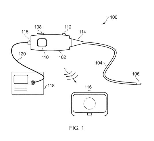
Fig. 1 is a schematic diagram of an electrosurgical
apparatus that is an embodiment of the invention;
Fig. 2 is a schematic cross-sectional view through an
instrument cable for an electrosurgical apparatus that is an
embodiment of the invention;
Fig. 3 is a schematic cross-sectional view through a
first example distal end of an instrument cable and instrument
tip of an electrosurgical apparatus that is an embodiment of
the invention;
Fig. 4 is a schematic cross-sectional view through a
second example distal end of an instrument cable and
instrument tip of an electrosurgical apparatus that is an
embodiment of the invention;
Fig. 5 is a schematic cross-sectional view through a
third example distal end of an instrument cable and instrument
tip of an electrosurgical apparatus that is an embodiment of
the invention;
Fig. 6 is a cut-away side view showing internal optical
components of a handpiece for an electrosurgical apparatus
that is an embodiment of the invention;
Fig. 7 is a cut-away side view showing a steering control
mechanism mounted in a handpiece for an electrosurgical
apparatus that is an embodiment of the invention;
Fig. 8 is a schematic diagram of a handpiece with
detachable cable that can be used in an electrosurgical
apparatus that is an embodiment of the invention; and
Fig. 9 is a schematic circuit diagram of the optical
components within a handpiece for an electrosurgical apparatus
that is an embodiment of the invention.
DETAILED DESCRIPTION; FURTHER OPTIONS AND PREFERENCES
CA 03051522 2019-07-24
WO 2018/178252
PCT/EP2018/058112
14
Fig. 1 is a schematic view of an electrosurgical
apparatus 100 according to the present invention. The
electrosurgical apparatus 100 comprises a handpiece 102 and a
flexible instrument cable 104 extending away from the
handpiece 102 in a distal direction. The flexible instrument
cable is suitable for insertion into the body to access a
treatment site. The flexible instrument cable 104 may have a
biocompatible coating on its external surface so that it can
be directly inserted into tissue. The instrument cable 104
may be introduced percutaneously or in a minimally invasive
manner via a natural orifice. In some examples, the
instrument cable 104 may be used with a separate surgical
scoping device (not shown), such as an bronchoscope,
endoscope, laparoscope or the like. In other examples, the
instrument cable may be introduced through a guiding catheter.
However, it may be particular advantageous for the instrument
cable to be inserted directly (i.e. without surrounding
components) to enable it to reach regions of the body that are
difficult to access.
The instrument cable 104 in the invention has two
functions: carrying microwave electromagnetic (EM) energy
and/or radiofrequency (RF) EM energy to the treatment site,
and carrying optical radiation for the purposes of imaging or
sensing properties of the treatment site. As explained in
more detail below, the instrument cable 104 of the invention
provides these two functions in a particularly compact manner,
by combining the two functions with in a common structure. In
a particular example, a optical channel for conveying optical
radiation to and/or from the treatment site may be provided
within an energy conveying means for the microwave and/or RF
electromagnetic (EM) energy. In one example, the optical
channel may act as an observation channel arranged to carry
optical signals to and from the treatment site to enable an
image of the treatment site to be output from the handpiece
102. The handpiece may include an observation port (not
CA 03051522 2019-07-24
WO 2018/178252
PCT/EP2018/058112
shown) for viewing the image. However, in a preferred
arrangement, the handpiece 102 may be arranged to transmit the
image to a separate display device 116. The image may be
transmitted via a wireless connection, e.g. via WiFi or any
5 other suitable networked communication configuration. The
display device 116 may be any device with a display screen
that is capable of receiving image data. The display device
116 may be portable, e.g. a laptop or tablet computer, a
smartphone, or the like. The apparatus of the invention may
10 include the display device, so that the benefits of the
invention can be used in locations that do not have local
display facilities.
An electrosurgical generator 118 is connected to the
handpiece 102 via a cable 120 (e.g. a coaxial cable) which
15 carries the RF and/or microwave energy into the handpiece 102.
The generator 118 may be of the type described in WO
2012/076844, for example. The handpiece 102 comprising a
connector port 115, which may be a QMA connector port or the
like. The connector port 115 may be arranged to electrically
connect the cable 120 to an energy conveying structure in the
instrument cable 104. This electrical connection may be
provided by a "T" connection between a coaxial cable from the
generator and a coaxial transmission line of the energy
conveying structure. Preferably there is a filter or choke
between the "T" junction and an instrument port on the
generator to prevent microwave leakage to the instrument port.
This must be placed at half a wavelength at the microwave
frequency from the "T" junction so that the "T" junction has a
high return loss, i.e. does not reflect a significant
proportion of the microwave energy back to the generator. The
proximal end of the transmission line in the energy conveying
structure is open circuit if RF energy is to be transmitted so
as not to short out the RF voltage. It is also insulated and
protected so that it does not break down for RF voltages or
expose the operator to high RF voltages.
CA 03051522 2019-07-24
WO 2018/178252
PCT/EP2018/058112
16
The instrument cable 104 has at its distal end an
instrument tip 106 that is arranged to receive the RF and/or
microwave energy from the energy conveying means in the
insertion cable 104. The instrument tip 106 includes an
energy delivery portion for delivering the received RF and/or
microwave energy into biological tissue, e.g. to assist in
treatment, e.g. cutting or coagulation.
The distal end of the instrument cable 104 may be
steerable, e.g. to facilitate location of the instrument tip
106 in a desired position for treatment, and/or to enable
optical radiation to be directed as desired, e.g. to obtain
images of different parts of the treatment site or to take
measurements in different positions. As explained below, in
some examples the instrument cable 104 may include one of more
control elements (e.g. e.g. pull/push rods or control wires)
to facilitate steering. The control elements may pass out of
a proximal end of the instrument cable to engage a steering
mechanism mounted within the handpiece 102. The steering
mechanism may be operable to extend and retract the control
elements to effect action at the instrument tip. The steering
mechanism may include an actuator mounted on the handpiece
102. In this example, the actuator is a rotatable knob 110.
Rotation of the knob 110 relative to the housing can be
converted to linear motion of the control element(s) via a
suitable conversion mechanism mounted in the handpiece 102.
One example of a steering mechanism is discussed below with
reference to Fig. 7.
To limit the angle at which the proximal end of the
instrument cable 104 can be bent relative to the handpiece
102, a conical restrictor 114 is fitted over the proximal end
of the instrument cable 104. The conical restrictor 114 is
secured to a distal end of the handpiece 102 and thus limits
the movement of the cable to prevent it from experiences
unwanted stresses.
CA 03051522 2019-07-24
WO 2018/178252
PCT/EP2018/058112
17
As discussed in more detail below, the handpiece 102
comprises a housing that contains components associated with
generating and controlling the optical radiation that can be
conveyed along the optical channel in the instrument cable
104. For example, the handpiece 102 may contain a power
source, such as a cell or other battery, an optical source,
such as a light emitting diode (LED) or the like, and one or
more optical elements for directing optical radiation from the
optical source or from the treatment site in a desired manner.
The optical elements may include a control interface 112 on
the outer surface of the housing, to enable a user to control
the optical elements in use. For example, the control
interface 112 may control an intensity optical radiation
delivered to the treatment site, or may control one or more
lenses to assist in focussing an image signal received from
the treatment site on to an optical sensor. In one example,
an optical detector (e.g. a camera or the like) may be mounted
in the handpiece to receive optical radiation returned from
the treatment site in order to capture and transmit an image
signal to the display device 116. In one example, the optical
components may resemble a conventional fiberscope.
The handpiece 102 may include a power switch (not shown)
for activating and deactivating the apparatus. The handpiece
102 may include a charging port (not shown) for connecting the
power source to an external power supply to enable it to be
recharged.
Fig. 2 is a schematic cross-sectional view through a
short length of one example of an instrument cable 104 in
which an energy conveying structure and optical channel are
combined in a compact manner. Generally speaking, the
instrument cable 104 shown in Fig. 2 is a coaxial transmission
line 125 having a hollow inner conductor that is capable of
carrying an optical channel, which typically comprises one or
more optical fibre bundles. The optical channel may thus be
conveyed within the energy conveying means. This is in
CA 03051522 2019-07-24
WO 2018/178252
PCT/EP2018/058112
18
contrast to conventional surgical soaping devices, where an
observation channel is typically formed separately from (i.e.
outside) and parallel to an instrument channel.
In more detail, the coaxial transmission line 125
comprises an outer conductor 124, an inner conductor 128, and
a dielectric material 126 separating the inner conductor 128
from the outer conductor 124. The inner conductor 128 may be
formed on an innermost insulating conduit 130. The conduit
130 is hollow to define a central passage 132 along a
longitudinal axis of the coaxial transmission line 125. The
passage 132 is used to convey optical radiation as discussed
further herein. The passage 132 may have a diameter 134 sized
to receive the optical cable of a fiberscope. Such cables
typically have a diameter of around 1 mm, so the passage may
have a diameter of equal to or less than 1.5 mm, e.g. equal to
or less than 1.2 mm.
An outer surface of the outer conductor 124 may be
surrounded by a protective sheath 122. The sheath 122 may be
flexible to enable manipulation, e.g. steering, of the
instrument cable. The sheath 122 may be made from a
biocompatible material or may have a biocompatible outer
coating to enable the cable to be inserted directly into
tissue. Any suitable material may be used, but PEEK is
particularly preferred. As explained below, in some examples,
the protective sheath 122 may be used to assist steering of
the instrument tip.
Fig. 3 is a schematic cross-sectional view through a
distal end of a first example instrument cable 104. Features
in common with Fig. 2 are given the same reference number and
are not described again. In this example, the instrument tip
106 comprises a dome 136 of dielectric material that is
attached (e.g. bonded or otherwise affixed) to the distal end
of the instrument cable 104. The dome 136 may be made of a
ceramic, or other similar material that can form a radiating
CA 03051522 2019-07-24
WO 2018/178252
PCT/EP2018/058112
19
antenna to delivery microwave EM energy received from the
coaxial transmission line 125.
In this example, the inner conductor 124 has a distal
portion 142 that extends distally beyond a distal end of the
outer conductor 128. The distal portion 142 extends inside
the dome 136. A suitable recess may be machined in the dome
136 to receive the distal portion 142. The dielectric
material 126 may also having a distal portion 144 that extends
beyond the distal end of the outer conductor. The distal
portion 144 may provide an attachment surface for securing the
dome 136 to the coaxial transmission line 125. The distal
portion 142 of the inner conductor may extend beyond a distal
end of the distal portion 144 of the dielectric material 126.
The dome 136 may have a bore formed therein which aligns
with the passage 132 in the instrument cable 104 when the dome
136 is secured to the instrument cable. The bore terminates
at a distal aperture 146 on the outer surface of the dome 136.
An optical cable 140 is conveyed through the passage 132 and
bore and terminates at the aperture 146. In a preferred
embodiment, the optical cable 140 comprises an illumination
fibre bundle for conveying an illumination signal from the
handpiece to the treatment site. The illumination signal is
optical radiation for illuminating or probing the treatment
site, e.g. to make it visible for imaging or other types of
optical sensing. The optical cable 140 may further comprise
an imaging fibre bundle for carrying optical radiation from
the treatment site, i.e. reflected or otherwise emitted from
the treatment site, back to the handpiece, e.g. for detection.
In a development of the structure discussed above, the
dome 136 may optionally include a transducer element suitable
for transmitting ultrasonic energy to the treatment site. For
example, the transducer element may be made from a
piezoelectrically active ceramic. The instrument cable 104
may be arranged to deliver an operating voltage for the
transducer element from the handpiece. In this arrangement,
CA 03051522 2019-07-24
WO 2018/178252
PCT/EP2018/058112
the apparatus may be capable for selective delivery of
microwave, RF or ultrasonic energy for treatment in
combination with an integrated system for visualising the
treatment site.
5 In Fig. 3, the protective sheath 122 is anchored at its
distal end to the coaxial transmission line 125 by suitable
bonding or physical connection (e.g. crimping or the like).
The sheath 122 includes a cut-out portion 138 on one side
thereof. The cut-out portion 138 may be a elongate oval or
10 similar shape. The cut-out portion 138 defines a preferential
lateral deformation axis for the sheath 122. In other words,
it provides a structure weakness in the outer surface of the
sheath 122 whereby when the sheath is put under compression it
will preferentially bend over towards the side where the cut-
15 out portion 138 is located. The cut-out portion 138 thus
effectively acts as a living hinge.
Meanwhile, a proximal end of the sheath 122 is secured to
a slider associated with the handpiece 102. The slider is
movable relative to the handpiece through actuation of a
20 steering mechanism. A proximal portion of the coaxial
transmission line 125 is anchored so that it does not move
relative to the handpiece. Movement of the slider therefore
introduces a compressive or tensile force in the sheath
relative to the coaxial transmission line, which in turn
causes the instrument tip to bend or straighten in the sense
defined by the living hinge.
In one example, bending of the instrument cable can be
constrained within a distal portion thereof by making the
protective sheath more rigid along its length expect at the
distal portion. This can be done by providing a stiffening
layer in or on the protective sheath. The stiffening layer
may be provided by braiding on the protective sheath or by a
jacket mounted over the instrument cable.
Fig. 4 is a schematic cross-sectional view through a
distal end of a second example instrument cable 104. Features
CA 03051522 2019-07-24
WO 2018/178252
PCT/EP2018/058112
21
in common with Fig. 3 are given the same reference number and
are not described again. In this example, the steering
mechanism is incorporating into the dielectric material 126 of
the coaxial transmission line 125. In principle these allows
for removal of the protective sheath 122, which enables the
instrument cable to have a smaller overall diameter. Although
not shown in Fig. 4, there may still be a thin biocompatible
coating formed on the outer surface of the outer conductor
128.
In Fig. 4 the steering is effected by one or more control
wires 150, 154 that extend through the dielectric material 126
of the coaxial transmission line 125. The control wires 150,
154 may be made from a material having a similar dielectric
constant to the dielectric material 126 to prevent them from
disrupting the conveyed energy. For example, the control
wires may be made from drawn PEEK fibre, whereas the
dielectric material 126 may be an extruded PTFE tube or the
like.
In this embodiment there are two control wires 150, 154
mounted on opposite sides of the instrument cable 104. There
may be three of more control wires arranged around the
circumference of the instrument cable to enable it to be
steered in any direction. Each control wire 150, 154 is
secured to the instrument tip (e.g. the dome 136) at a
respective anchor point 152, 156.
Each control wire 150, 154 may be conveyed through a hole
148 formed in the dielectric material 126.
Similarly to the example discussed with reference to Fig.
3, the proximal end of each control wire 154, 156 is connected
to a steering mechanism that is arranged to vary the linear
position of the control wire with respect to the coaxial
transmission line 125 (which may be fixed relative to the
handpiece). Pulling the control wire back towards the
handpiece causes the instrument cable to bend towards the side
at which the anchor point for that control wire is located.
CA 03051522 2019-07-24
WO 2018/178252
PCT/EP2018/058112
22
Fig. 5 is a schematic cross-sectional view through a
distal end of a third example instrument cable 104. Features
in common with Fig. 4 are given the same reference number and
are not described again. The steering mechanism in Fig. 5
makes use of one or more control wires 160, 164 in a similar
way to the example discussed with reference to Fig. 4.
However, in this example, the control wires 160, 164 are
mounted in the protective sheath 122 that surrounds the
coaxial transmission line 125. The protective sheath 122
therefore comprises a multi-lumen tube, e.g. with a central
lumen for conveying the coaxial transmission line and optical
channel combination, and one or more outer lumens for
conveying a respective control wire. Each control wire 160,
164 may be secured to the protective sheath 122 at a
respective anchor point 162, 166 located at a distal end
thereof.
Fig. 6 is a cut-away side view through the handpiece 102
to show some of the internal components. The handpiece 102
comprises a housing 170, which may be a hollow shell for
containing the internal components. The housing 170 may have
apertures in its outer surface to provide access either for a
user to manipulate the components (e.g. for steering or
focussing) or for energy to be coupled into the device. The
housing 170 may comprises a plurality (e.g. two) portions
which are securable together after the internal components are
mounted therein.
In Fig. 6, for clarity only the optical components and
associated power and control components are shown. Fig. 7
shows components for the steering mechanism. In addition to
these components, the handpiece 102 carries the coaxial
transmission line from the connector port 115 at the rear
(proximal) end of the handpiece through a proximal aperture
174 and around the other internal components towards the cable
104.
CA 03051522 2019-07-24
WO 2018/178252
PCT/EP2018/058112
23
The housing 170 has a fiberscope body 172 mounted
therein, e.g. clipped into a recess formed in the housing to
hold the fiberscope body 172 stationary relative to the
housing 170. The fiberscope body comprises a front (distal)
input light coupling portion that has a light input port 182
mounted thereon. A light source 180, which in this case is a
surface mounted LED secured to an inside surface of the
housing 170, is located across the light input port 182 to
provide an illumination signal for the fiberscope. The front
input light coupling portion couples the illumination signal
into an illumination bundle of optical fibres which are
carried in an optical channel 184 that passes within the
instrument cable 104 (not shown). The housing 170 includes a
front (distal) aperture 175 through which the instrument cable
104 (including the optical channel 184) passes out of the
housing 170.
The optical channel 184 also includes an imaging bundle
of optical fibres which convey optical radiation from the
treatment site back to the fiberscope body 172. The imaging
bundle typically has one or more micro-lenses at a distal end
thereof to focus the optical radiation from the treatment site
into the imaging bundle. The fiberscope body 172 comprises a
set of optical elements (e.g. lenses) that are arranged to
focus optical radiation received from the imaging bundle to
allow it to be viewed through a viewport at the rear
(proximal) end of the fiberscope body 172. The fiberscope
body 172 may include a focus adjuster 190 for varying the
focal length of the set of optical elements. The focus
adjuster 190 may be a rotatable barrel. The housing may
include a window in a side surface thereof to allow an
operator to contact and rotate the barrel.
In the arrangement shown in Fig. 6, the viewport is in
optical communication with an output lens arrangement 188 that
focusses an image onto an image sensor 186 (e.g. a digital
camera or other suitable device for converting optical
CA 03051522 2019-07-24
WO 2018/178252
PCT/EP2018/058112
24
radiation into an encoded image). In one example, the
conventional output optics found in the viewport of a
fiberscope may be replaced by a reverse fisheye lens that acts
to spread the optical radiation received from the imaging
bundle over a sensing area of the image sensor 186.
A controller 176 is mounted in the housing 170. The
controller 176 may be operably connected to the image sensor
186 and the light source 180 to control operation of the
fiberscope. The controller 176 may comprise a microprocessor
or a single board computer, such as a Raspberry Pi or the
like. As discussed below with reference to Fig. 8, the
controller 176 may also be operably connected to a transceiver
for communicating images captured by the image sensor 186 to a
remote device for display.
The housing 170 may include a power source 178 such as a
cell or battery. In one example, the power source 178
comprises a 18650 lithium ion cell or the like. The power
source 178 may be rechargeable, e.g. through a suitable
charging port located in an outer surface of the housing 170.
The power source 186 may provide energy to operate the light
source 180, the controller 176, the image sensor 186 and the
transceiver (not shown). The handpiece 102 may include an
ON/OFF switch to activate and deactivate the device in order
to conserve power when the apparatus is not in use.
The fiberscope discussed above with reference to Fig. 6
may resemble a conventional fiberscope device, albeit with its
eyepiece replaced by the output lens arrangement 188 and image
sensor 186.
Fig. 7 is a cut-away side view through the handpiece 102
to show internal components that provide steerability to the
instrument cable. Features in common with examples discussed
above are given the same reference number and are not
described again. As shown in Fig. 7, the housing 170 may
comprises a steering mechanism that is based on a rack and
pinion to transform rotation motion of the rotatable knob 110
CA 03051522 2019-07-24
WO 2018/178252
PCT/EP2018/058112
into longitudinal sliding motion of the protective sheath 122
with respect to the coaxial transmission line 125.
The rotatable knob 110 is rotatably mounted on the
housing 170 by a shaft which is retained in an aperture formed
5 in the housing 170 by a flange. The shaft extends below the
flange to provide a pinion gear 192 that is operably engaged
with a rack 194 that is slidably mounted within the housing
170. The portion of the rotatable knob 110 that is located
outside the housing 170 may have a grip shaped to assist
10 rotation.
The rack 194 is slidable in a longitudinal direction,
i.e. in a direction substantially aligned with or parallel to
the axial direction of the coaxial transmission line. The
rack 194 is operably connected to or formed integrally with a
15 push arm 196. The push arm 196 comprises a collar 198 that
fits over a proximal portion of the instrument cable 104. In
this example, the collar 198 is attached to the protective
sheath 122 of the instrument cable 104, e.g. at an attachment
point 197. Meanwhile, the coaxial transmission line 125 is
20 fixed relative to the housing 170 at an anchor point 199.
Longitudinal movement of the collar 198 relative to the
housing therefore introduces a relative force between the
coaxial transmission line 125 and the protective sheath 122 to
cause bending at the distal end of the instrument cable 104 as
25 discussed above with reference to Fig. 3.
In other examples, the push arm 196 may be connected to
one or more control wires that extend through the instrument
cable in the manner discussed with reference to Figs. 4 and 5.
In these examples, a proximal portion of the coaxial
transmission line remains fixed relative to the housing, but
it may not be necessary for the push arm 196 to be secured to
the protective sheath 122.
In some examples, the anchor point 199 may have a dual
function. Firstly it may secure a proximal portion of the
coaxial transmission line to the housing in the manner
CA 03051522 2019-07-24
WO 2018/178252
PCT/EP2018/058112
26
discussed above. Secondly it may comprise a transformer for
interconnecting a first energy conveying structure (which may
be a conventional coaxial cable) that extends between the
connector port 115 at the input aperture 174 and the anchor
point 199 with a second energy conveying structure, which is
the hollow coaxial transmission line 125 that extends along
the instrument cable 104. In some examples, an impedance of
the coaxial transmission line 125 may be different from an
impedance of the first energy conveying structure. The
transformer may provide an impedance matching function to
reduce or eliminate energy losses within the handpiece 102.
Fig. 8 is a schematic diagram of another example of a
handpiece 200 that can be used in an electrosurgical apparatus
that is an embodiment of the invention. Features in common
with the handpiece 102 described above are given the same
reference number and are not described again. The handpiece
200 depicts a schematic example of an embodiment in which the
instrument cable 104 may be a detachable and, optionally,
disposable item.
The handpiece 200 comprises a main body 202 which houses
the internal components discussed above with respect to Figs.
6 and 7. At a front (distal) end of the main body 202, there
are two connection ports 206, 208. A first connection port
206 is for transferring the microwave and/or RF energy from
the main body 202 into the instrument cable 104. A second
connection port 208 is for transferring the optical radiation
to and/or from the instrument cable 104. The first connection
port 206 may be QMA port or the like. The second connection
port 208 may be an optical coupler or fiberscope connector.
The instrument cable 104 in this example may have a
proximal end case 204 that is arranged to engage with and
attach to a distal portion of the main body 202. In this
example, the proximal end case 204 may also act as a
deflection limiting means for the instrument cable 104 to
prevent it from experience too much bending at the handpiece.
CA 03051522 2019-07-24
WO 2018/178252
PCT/EP2018/058112
27
The proximal end case 204 may comprises engagement features
(not shown), e.g. on an inner surface thereof, which cooperate
with corresponding features on the main body 202 to secure the
two parts together.
The proximal end case 204 may define a recess in which a
pair of connectors 210, 212 are mounted. A first connector
210 may be receivable in the first connector port 206 when the
proximal end case 204 is mounted on the main body 202. The
first connector 210 is a proximal terminus of the coaxial
transmission line 125 that is conveyed by the instrument cable
104. When the first connector 210 is operably connected to
the first connector port 206, microwave and/or RF energy from
the main body 202 can be transferred into the instrument cable
104.
A second connector 212 may be receivable in the second
connector port 208 when the proximal end case 204 is mounted
on the main body 202. The second connector 212 is a proximal
terminus of a optical channel 140 that is conveyed by the
instrument cable 104. When the second connector 212 is
operably connected to the second connector port 208, optical
radiation can be transferred into and out of the instrument
cable 104.
Fig. 9 is a schematic circuit diagram of a circuit
arrangement 250 within a handpiece for an electrosurgical
apparatus that is an embodiment of the invention. The circuit
arrangement comprises a controller 252, which may be a
microprocessor or a single board computer such as a Raspberry
Pi or the like. The controller 252 is connected to control an
image sensor 258 through a first interface 260. In this
example, the image sensor 258 is an 8 megapixel camera. The
controller 252 is also connected to a transceiver 254 via a
second interface 256. For example, the transceiver 254 may be
a USB WiFi dongle connected to the microprocessor via a micro
USB port or the like. This arrangement forms an output
circuit for capturing and transmitting or broadcasting images
CA 03051522 2019-07-24
WO 2018/178252
PCT/EP2018/058112
28
from the fiberscope. The controller 252 may have a memory
with software instructions stored thereon which, when
executed, cause the controller to record images using the
camera and to display those images on a remote display device,
e.g. a computer, tablet or smart phone. In one example, the
device may broadcast to a local wireless hotspot to which
other devices can connect. A user can navigate to a specific
URL (e.g. 192.168.42.1/vision.php) to access the images.
Further information can also be shown on the display,
including patient information, date/time and any other
information required.
In a development of the arrangement shown in Fig. 9, the
controller 252 may communicate with a user interface to enable
functionality and operation to be controlled or modified on
the fly. The user interface may be on the handpiece itself,
e.g. as a series of buttons and a display to show current
operational status and modification operations. Alternatively
or additionally, the user interface may be on a remote device
that is in networked communication with the controller 252 via
the transceiver 254. The controller 252 may thus be operated
remotely. Examples of on the fly control include
modifications such as image brightness, contrast and
sharpness, and switching between recording of still images and
video.
Where the controller 252 is a single board computer, it
may comprise ports that are not used, for example a mini HDMI
interface 262 and a micro SD interface 264.
The circuit arrangement 250 comprises a power source 270,
which may be a rechargeable cell or the like, connected to the
controller 252 via a charging circuit 268. The charging
circuit is arranged to regulate voltage. It may include a
connector port 269, e.g. a micro USB socket, to enable the
circuit arrangement to be connect to a mains supply to allow
for recharging the power source, in one example, the power
source 270 is a 18650 lithium ion cell, and the charging
CA 03051522 2019-07-24
WO 2018/178252
PCT/EP2018/058112
29
circuit is arranged to provide both a voltage increase and
regulation (typically from 3.7 - 4.2 V to 5 V). An ON/OFF
switch 266 may be provided on the connection between the
charging circuit 268 and the controller 252.
The circuit arrangement 250 further comprises a constant
current circuit 271 connected between the power source 270 and
a light source 272. In this example, the light source is an
LED. It may be desirable to vary the illumination level at
the treatment site, so the circuit further comprises a
potentiometer 274 to allow the LED to be dimmable. The
potentiometer 274 may have an actuator associated with it that
is accessible to the user through an aperture on the outside
of the handpiece. The actuator may be a thumbwheel, slider or
any other suitable control element. The constant current
circuit 271 is arranged to ensure that the light source 272
only pulls a limited current (e.g. approximately 500 mA) from
the power source 270. This is to both conserve charge but to
also minimise the risk of higher current levels causing
unwanted heating within the handpiece.
The circuit arrangement 250 and apparatus discussed above
may be combined into a particular example as follows. The
main assembly of the handpiece may comprise a fiberscope with
a 1 mm optical channel having both send and return fibre
bundles and an integrated lens assembly at the proximal end.
The optical channel may be housed within a hollow coaxial
transmission line along which microwave power can be
delivered. The coaxial transmission line may terminate at a
distal cylindrical ceramic (e.g. Macor) radiating tip with a
rounded end and concentric hole for vision through the fibre.
The image from the fiberscope may be magnified using a
fish-eye lens in reverse, and captured via a camera and
processed through a single board computer processor (such as a
Raspberry Pi Zero), zoomed digitally and broadcast or uploaded
for access via WiFi. A lithium-ion cell or battery can power
the processor and a single LED light-source fed into a light-
CA 03051522 2019-07-24
WO 2018/178252
PCT/EP2018/058112
port on the fiberscope lens assembly in order to illuminate
the body cavity at the distal end of the vision system.
The main assembly may be encapsulated within a plastic
vacuum-cast handpiece. Although this example operates using a
5 conventional fiberscope, this is not essential. In other
example a dedicated lens assembly may be built directly into
the handpiece.
The light source may be arranged to mimic daylight as
closely as possible, as this would be best for illuminating
10 the treatment site, and would closely mimic the halogen
sources with which bronchoscopic surgeons are accustomed. The
LED used may thus be a white light LED having around 5.8
Kelvin colour temperature. The LED may have an output of
around 50-100 lumens in order to sufficiently illuminate the
15 treatment site.
The combined optical channel and coaxial transmission
line may be housed inside a protective sheath (e.g. made from
PEEK), and may be steerable with one degree of freedom based
upon a living-hinge type mechanism. To provide predictable
20 steering, a length of material may be removed from one side of
the protective sheath at its distal end such that it creates a
weakness. The sheath have be secured to the combined optical
channel and coaxial transmission line at its distal end. When
sheath is pushed or pulled from the proximal end, the distal
25 end is therefore forced to bend, allowing movement and vision
around corners.
To prevent ingress of fluids, the protective sheath may
be covered in heat-shrink tubing. The instrument cable may
have a maximum outer diameter equal to or less than exceed 3.5
30 mm. The heat-shrink tubing may act to hold the assembly
together so that the protective sheath does not exceed its
elastic limit and permanently deform.
At the proximal end, the handpiece may have a rotatable
knob or handle which, when turned, causes the protective
CA 03051522 2019-07-24
WO 2018/178252
PCT/EP2018/058112
31
sheath to move back and forth along the length of the coaxial
transmission line, providing the steering capability.
Other steering mechanisms may be used. For example, a
control wire (e.g. made from nitinol) may be fed between the
outer conductor of the coaxial transmission line and an inner
surface of the protective sheath. The control wire may be
fastened on an outer surface of the protective sheath at its
distal end. The control wire may run through fixed guides on
the outer surface of the coaxial transmission line so as to
reliably pull in any given direction. There may be a
plurality of control wires. Each control wire may be fixed to
a rotary barrel at the proximal end of the instrument cable.
When the barrel is rotated in a first sense, a first control
wire may be pulled in one direction while a second control
wire is released in the other direction. This can provide
steering about one axis at the distal end. Further two wires
could be added to give another axis of movement, which when
combined could give full 360-degree steerability.