Note: Descriptions are shown in the official language in which they were submitted.
..
- 1 -
TITLE OF THE INVENTION
STORMWATER CHAMBERS THERMOFORMED FROM COEXTRUDED SHEET MATERIAL
FIELD OF THE INVENTION
[0001] This application relates generally to molded plastic chambers for
water detention and, more particularly to an open bottomed, arch-shaped
molded plastic chambers that are buried in the ground to either receive storm
water runoff or be used in a septic system.
BACKGROUND OF THE INVENTION
[0002] Storm water runoff was historically directed into municipal storm
water drainage systems and released into a local body of water. However,
regulatory changes now mandate that storm water runoff must be collected
and directed to local soil where it can replenish groundwater supplies.
[0003] The traditional construction of these water handling systems has
included the use of concrete tanks and / or perforated pipes running through
infiltration trenches filled with relatively large pieces of gravel or crushed
stone. However, these stone-filled trench systems are expensive and labor
intensive to install. Additionally, stone-filled trenches are very inefficient
as the
stone occupies a substantial volume of the trench, which severely limits the
capacity of the system to handle relatively large surge volumes associated
with heavy storms. Likewise, both the stone and the perforated pipe are
susceptible to clogging due to, for example, particles or debris carried by
water during intense storms.
[0004] Molded plastic chamber structures were introduced to the
market to take the place of concrete structures for water handling. U.S.
Patent No. 5,087,151 to Robert J. DiTullio describes an early water handling
system that utilizes vacuum-molded polyethylene chambers that are designed
CA 3051680 2019-08-09
..
- 2 - ,
to be connected and locked together in an end-to-end fashion to provide a
buildable water handling system.
[0005] Water detention chambers are typically provided with a
corrugated arch-shaped cross-section and may be formed relatively long with
open bottoms for dispersing water to the ground. The chambers are typically
buried within crushed stone aggregate or other water permeable granular
medium that typically has 20-40 percent or more void space. The chambers
serve as water reservoirs in a system that includes both the chambers and
surrounding crushed stone. The crushed stone is located beneath, around,
and above the chambers and acts in combination with the chambers to
provide paths for water to percolate into the soil, and also provides a
surrounding structure that bears the load of any overlying materials and
vehicles. The chambers will usually be laid on a crushed stone bed side-by-
side in parallel rows, then covered with additional crushed stone to create
large drainage systems. End portions of the chambers may be connected to a
catch basin, typically through a pipe network, in order to efficiently
distribute
high velocity storm water. Examples of such systems are illustrated in U.S.
Patent Nos. 7,226,241 and 8,425,148 to Robert J. DiTullio.
[0006] These types of chambers have had great success and have
become a standard in the industry due to the ease of installation and high
quality of the finished systems. One of the key concerns in the installation
of
these types of systems is maintaining the integrity of the chambers to avoid
being crushed, which would result in the loss of the interior space of the
chamber for handling large volumes of run off during intense storm conditions.
Some techniques that have been used include use of rib systems to improve
strength such as is disclosed in U.S. Patent No. 9,765,509.
[0007] Chambers have typically been formed by vacuum forming
sheets of high density polyethylene (HDPE) or by injection molding
polypropylene.
CA 3051680 2019-08-09
..
- 3 - [0008] High density polyethylene (HDPE) and products fabricated
therefrom will degrade when exposed to ultraviolet light, heat, and ozone. The
degraded polymer will suffer a loss of elasticity and tensile strength, and in
some cases may experience cracking. UV light promotes free radical
oxidation of the surface. Heat accelerates the process of oxidation and the
effects of oxidation can be observed sooner and are more severe as the
temperature increases. Since HDPE can become brittle when exposed to
sunlight, so carbon black is usually included in the polyethylene sheet
material
as a UV stabilizer.
[0009] A significant problem with conventional carbon black HDPE
chambers is heating from solar radiation. During summer months, and in
southern latitudes, where there are both high ambient temperatures, and
more intense sunlight, black HDPE chambers left in direct sunlight can
become overheated. For example, during the hot summer months when much
construction activity is typical, storm water detention chambers may be loaded
on a trailer to be shipped to a job location, then unloaded to sit for
prolonged
periods of time in the direct sun prior to installation.
[0010] Polyethylene, a thermoplastic material, will become more pliable
as the temperature of the material rises. Black HDPE chambers sitting in
direct sunlight absorb solar radiation and sometimes become excessively
pliable such that if they are loaded / unloaded / moved, they will be deformed
or otherwise damaged. Overheated chambers may deform either due to
stress while being moved, or as a consequence of installation of crushed rock
around and on the chambers.
[0011] Therefore, there is a need in the storm water management field
for a thermoplastic chamber system that is resistant to the effects of intense
sunlight such that the chambers retain their rigidity even when exposed to
solar radiation for prolonged periods of time.
CA 3051680 2019-08-09
..
- 4 -
SUMMARY OF THE INVENTION
[0012] Accordingly, it is an object of the present invention to provide a
storm water chamber that is resistant to the heating effects associated with
solar radiation.
[0013] It is a further object of the present invention to provide such a
storm water chamber that remains sturdy and rigid even if exposed to direct
sunlight for prolonged periods of time.
[0014] It is a yet another object of the present invention to provide such
a storm water chamber that reflects solar radiation and has a reduced
absorption of solar radiation as compared to conventional storm water
chambers.
[0015] These and other objectives are achieved by providing an arch-
shaped corrugated chamber that is formed from a vacuum-molded
polyethylene sheet where the sheet is formed of a first layer provided with an
increased reflectance additive that is bonded to a second layer. The first
layer
having an increased reflectance additive forms an exterior surface of the
corrugated chamber and the second layer forms an interior surface of the
corrugated chamber. The first and second layers are formed of a HDPE resin
or a blend of HDPE resins.
[0016] A method of manufacturing a water management system is
provided, comprising steps of forming a first layer of material with an
increased reflectance additive and a second layer of material and joining them
together, then vacuum-molding the sheet of material to form a chamber
having an elongated body with an arch-shaped configuration. The first and
second layers are formed of a HDPE resin or a blend of HDPE resins.
[0017] Other objects of the invention and its particular features and
advantages will become more apparent from consideration of the following
drawings and accompanying detailed description.
CA 3051680 2019-08-09
..
- 5 -
BRIEF DESCRIPTION OF THE DRAWINGS
[0018] FIG. 1 is an illustration of a chamber structure.
[0019] FIG. 2 is an illustration of a connection chamber.
[0020] FIG. 3 is an illustration of how the connection chamber of FIG. 2
is connected to the chamber structure of FIG. 1.
[0021] FIG. 4 is an illustration according to FIG. 3 of the connection
chamber coupled to the chamber structure.
[0022] FIG. 5 is illustrates a cross-sectional view of the sheet material
that is used in forming the chamber structure and the connection chamber.
[0023] FIG. 6 is another illustration of a chamber structure.
DETAILED DESCRIPTION OF THE INVENTION
[0024] Referring now to the drawings, wherein like reference numerals
designate corresponding structure throughout the views.
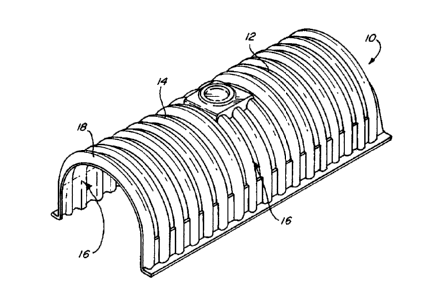
[0025] FIG. 1 is an illustration of a molded chamber structure 10
generally comprising an arch-shaped body portion 12 that includes a plurality
of upstanding corrugations 14. The body portion 12 is provided with an open
bottom such that side walls 16 are configured to rest on the surface of the
bed
of materials. Molded chamber structure 10 may be provided with a starting rib
18, which is designed to mate with end rib 116 on connection chamber 100
(FIG. 2). Molded chamber structure 10 typically comprises, for example, a
vacuum-molded high density polyethylene (HDPE) chamber.
[0026] FIG. 2 illustrates a molded connection chamber 100 comprising
an arch-shaped body 102 including a plurality of upstanding corrugations 104.
Connection chamber 100 also comprises side walls 106, which extend
downward to rest on the surface of the bed of materials having an open
bottom. Provided at a lower portion of side wall 106 is arch-shaped cut out
108 that may be formed as a relatively flat pre-formed section to be
optionally
CA 3051680 2019-08-09
, - 6 -
removed by a user. End wall 110 may be integrally molded with arch-shaped
body 102, or alternatively, may be provided as a removable wall section. A
relatively small arch-shaped cut out 112 may be provided at a lower end of
end wall 110, or a relatively large arch-shaped cut out 114 may be provide at
a lower end of end wall 110. An inspection port 118 may further be provided
on an upper surface of arch-shaped body 102. The inspection port 118 is
provided such that a user may visually inspect the interior of the connection
chamber 100 and correspondingly coupled molded chamber structures 10.
End rib 116 is located at one end of arch-shaped body 102 being provided as
a smaller rib than that plurality of upstanding ribs 104. In this manner, end
rib
116 may be mated with starting rib 18 provided on molded chamber structure
10. Connection is relatively simple and quick. The molded chamber structure
may simply be dropped down over connection chamber 100 as shown in
FIG. 3, to form a chamber row (FIG. 4).
[0027] While connection chamber 100 is illustrated connected to one
end of molded chamber structure 10, it is contemplated that it may be
positioned anywhere along the length of the row and that multiple connection
chambers 100 may be utilized in a single row to facilitate the free movement
of fluid throughout the field.
[0028] Conventionally, HDPE chambers fabricated according to ASTM
Standard F2922-13 are vacuum thermoformed from extruded HDPE sheets
formed from HDPE resins that include a carbon black additive. The carbon
black additive acts as a pigment, a conductive filler material, a particulate
reinforcement, and an ultraviolet light (UV) absorber. In the present
invention,
the amount of carbon black additive is significantly reduced or omitted from
the HDPE sheet forming the chamber, and is replaced with an additive or
plurality of additives that provide the chamber with UV protection,
antioxidant
protection, and a higher reflectance than a HDPE/carbon black chamber. As
used herein, the term "increased reflectance additive" means any additive
CA 3051680 2019-08-09
- 7 -
which provides an HDPE sheet material with a greater reflectivity of solar
radiation than conventional HDPE with carbon black as an additive.
[0029] A chamber fabricated from an HDPE sheet material having an
increased reflectance additive will exhibit greater reflectance and less
absorption of solar radiation, and thus will experience less solar heating of
the
chamber, and this a reduced likelihood of unintended deformation or buckling
of the chamber.
[0030] In preferred embodiments of the invention, the HDPE sheet
material used to form a chamber is a multilayer sheet in which an external
HDPE layer is provided with an increased reflectance additive while one or
more inner HDPE layers are conventional HDPE with carbon black as an
additive.
[0031] Turning now to FIG. 5 a cross section of a HDPE sheet 200 is
provided. The sheet 200 is co-extruded and includes a first layer 202 and a
second layer 204. The first layer 202 is bonded to second layer 204 at a joint
206. The sheet 200 may then be used in a vacuum-molding process that
forms chamber structure 10 or connection chamber 100 in a mold.
[0032] The first layer 202 constitutes the upper surface or exterior
surface of a chamber such as chamber structure 10 or connection chamber
100. The first layer 202 is provided with an increased reflectance additive.
The increased reflectance additive provides the first layer 202 with a greater
reflectance of solar radiation than typical black HDPE, to reduce the
absorption of solar radiation which contributes to overheating of chambers.
The increased reflectance additive desirably also provides ultraviolet and/or
antioxidant protection to the first layer 202. Alternatively, supplemental
additives may be used to provide ultraviolet and/or antioxidant protection to
the first layer 202. Supplemental antioxidant / ultraviolet (AO/UV) protective
additives may include paracrystalline carbon such as carbon black, amines,
phenolic and/or phosphates and/or thioesters.
CA 3051680 2019-08-09
..
- 8 -
[0033] Color pigments, other than carbon black (or other black
pigments), such as those listed below may be used in as an increased
reflectance additive.
Pigment* Composition TSR**
Blue 424 CoAl 42%
Yellow 10P110 NiSbTi 69%
Orange 10P225 CrSbTi 63%
Green 223 CoNiZnTi 25%
Brown 10P850 MnSbTi 35%
(*Pigment Product Codes of The Shepherd Color Company [see
https://vwvw.shepherdcolor.com/]).
("Total Surface Reflectance ¨ which is the percentage of the total solar
energy reflected by the pigment).
[0034] In one embodiment, color pigments are provided to the resin(s)
used to make the layer 202 in the form of color concentrates or liquid color
is
added to the resin used to form first layer 202.
[0035] In one embodiment, color pigments are provided to the resin(s)
used to make the layer 202 according to the process described in U.S. Patent
No. 9,969,881.
[0036] Increased reflective additives which are specifically formulated
to reflect infrared radiation is particularly effective. Such infrared
reflecting
additives may include mixed metal oxides (MMO) or complex inorganic
colored pigments (CICP).
CA 3051680 2019-08-09
..
. - 9 -
[0037] Other increased reflective additives may include reflective
mineral components such as fumed silica or ultra-fine calcined alumina or
borosilicate glass. Other reflective additives may include metalized films.
[0038] In other embodiments, the desired increased reflectance is
achieved by the use of coatings applied to the first layer 202.
[0039] The second layer 204 constitutes the lower surface or interior
surface of the chamber such as chamber structure 10 or connection chamber
100 and is a conventional HDPE materials with carbon black as an additive.
[0040] The relative thickness of the first layer 202 and the second layer
204 is selected according to considerations of ease of fabrication and cost of
materials. Typically the thickness of the first layer 202 will be 50% or less
of
the sheet 200 and the thickness of the second layer 204 will be 50% or more
of the sheet 200.
[0041] In FIG. 5, the sheet of material 200 illustrates an embodiment of
the invention where the first layer of material 202 comprises approximately
20% (depicted as ".2D" in FIG. 5) of a total thickness (depicted as "D" in
FIG.
5) of the sheet of material 200, while the second layer of material 204
comprises approximately 80% of the total thickness D (depicted as ".8D" in
FIG. 5). The 20%/80% relative thickness of the first layer 202 and the second
layer 204 provides an effective solution to the issue of solar heating without
excessively increasing the cost. However, other relative thicknesses may be
used in accordance with the invention.
[0042] First layer 202 and second layer 204 may be formed of the
same material or from different materials. First layer 202 and second layer
204 may be composed of one or more resins, and may have the same or
different compositions. In many embodiments, HDPE is used for both the first
layer 202 and second layer 204. In a preferred embodiment, first layer 202
and second layer 204 are formed from a blend of resins.
CA 3051680 2019-08-09
- 10 - [0043] Appropriate resins for use in first layer 202 and second layer
204 are Marlex High Density Ethylene Hexene Copolymer resins distributed
by the Chevron Phillips Chemical Company LP (CPChem). Marlex 5502
HDPE has the following properties: density 0.955 g/cm3, tensile yield strength
28 MPa, flexural modulus 1,378 MPa. Marlex 50100 HDPE has the following
properties: density 0.948 g/cm3, tensile yield strength 25 MPa, flexural
modulus 1,200 MPa.
[0044] The Marlex 5502 HDPE has a greater density, a greater
tensile yield strength and a greater flexural modulus than the Marlex 50100
HDPE. However, chambers made with the Marlex 50100 have a greater
impact strength than the Marlex 5502 HDPE, and therefore Marlex 50100
HDPE would be assumed to be a preferable resin for use in chamber
applications.
[0045] Surprisingly however, it has been found that a blend of Marlex
5502 HDPE and Marlex 50100 HDPE resins results in a HDPE sheet
material having a higher impact strength than a HDPE sheet material made
using either resin by itself. The blend of the two resins results in
thermoformed chambers with increased stiffness compared to either resin by
itself. The chamber stiffness is further improved by the co-extrusion of first
layer 202 and a second layer 204 and bonding them together. During
preliminary arch compression tests conducted generally in accordance with
ASTM Standard F2922-13, Section 6.2.9, a sample of a thermoformed
chamber made from a blend of Marlex 5502 HDPE and Marlex 50100
HDPE resins demonstrated greater strength than a sample of a thermoformed
chamber made with the Marlex() 50100 material alone.
[0046] In one embodiment, the blend can comprise approximately 50%
Marlex 50100 and approximately 50% Marlex 5502.
[0047] If consistency of mechanical properties throughout the thickness
of the sheet 200 which forms the walls of the chamber structure 10 or
connection chamber 100 is preferred or required, first layer 202 and second
CA 3051680 2019-08-09
..
- 11 - layer 204 will preferably both be fabricated from the same resin or
resin blend.
If variation of mechanical properties throughout the thickness of the sheet
200
which forms the walls of the chamber structure 10 or connection chamber 100
is preferred or required, first layer 202 and second layer 204 will preferably
be
fabricated from different resins or resin blends.
[0048] One embodiment of the invention that is considered to provide
increased strength and reduced solar heating is a sheet 200 composition as
follows:
First layer 202: 20% (of sheet 200 thickness) 50% Marlex 50100 and
50% Marlex 5502 blend (or their equivalents) with Carolina Colors
Process Blue with AO/UV (antioxidant/ultraviolet) package
Second layer 204: 80% (of sheet 202 thickness) 50% Marlex 50100
and 50% Marlex 5502 blend (or their equivalents) with carbon black.
[0049] Weathering tests of a prototype molded chamber has shown
that 50% Marlex 50100 and 50% Marlex 5502 blend (or their equivalents)
with Carolina Colors Process Blue is effective for providing the level of UV
and AO protection required while simultaneously maintaining the strength and
other important properties needed for this particular application including
superior tensile strength and flex modulus.
[0050] FIG. 6 illustrates a molded chamber structure 10 fabricated from
a coextruded HDPE sheet 200 having a blue first layer 202 and a black
second layer 204 (not shown) according to the embodiment of the invention
described in the preceding two paragraphs. Chamber 10 includes an arch-
shaped body portion 12 that includes a plurality of upstanding corrugations 14
where the body portion 12 is provided with an open bottom such that side
walls 16 are configured to rest on the surface of the bed of materials. End
wall
20 may be integrally molded with arch-shaped body portion 12 as illustrated,
or alternatively, may be provided as a removable wall section. A number of
pre-formed arch-shaped configurations 22, 22' maybe integrally formed into
CA 3051680 2019-08-09
..
. - 12 -
end wall 20, or a relatively large arch-shaped cut out 24 may be provide at a
lower end of end wall 20. Likewise, a pre-formed cutout 26 designed to
receive a pipe or other configurations, may be provided in end wall 20.
Integrally pre-formed structures 28 are provided in end wall 20 to enhance
structural rigidity of the end wall 20 for the arch-shaped body portion 12.
[0051] A method of making a molded chamber structure 10 includes
the following steps. A first extrusion machine is loaded with an HDPE resin
pellets or a blend of different HDPE resin pellets. An increased reflectance
additive and any other colorants, UV stabilizers or antioxidants are added to
the HDPE resin pellets or a blend of different HDPE resin pellets. The mixture
to be processed is drawn into a screw extruder. The rotating screw forces the
plastic pellets into a heated barrel. The pressure and friction and heat melt
the
plastic pellets into a molten plastic and it is extruded from a die to form a
continuous web of first layer 202. Concurrently, a second extrusion machine is
loaded with an HDPE resin pellets or a blend of different HDPE resin pellets.
A carbon black additive is added to the HDPE resin pellets or a blend of
different HDPE resin pellets. The mixture to be processed is drawn into a
screw extruder. The rotating screw forces the plastic pellets into a heated
barrel. The pressure and friction and heat melt the plastic pellets into a
molten
plastic and it is extruded from a die to form a continuous web of second layer
204. The two continuous webs of layers 202 and 204 are then directed so
they are positioned one above the other, and the two continuous webs of
layers 202 and 204 are fed through a pair of rollers to join the two layers
together. The two joined layers 202 and 204 are typically cooled by pulling
them through a set of chilled rollers. The web formed of the two joined layers
202 and 204 is then cut into appropriate size sheets 200.
[0052] A sheet 200 is then passed through a heater such as a radiant
quartz heater system until the sheet 200 is in a pliable plastic state for
thermoforming, the sheet is pre-stretched, then thermoformed in the cavity of
a vacuum mold (with or without a male plug) into a chamber structure 10 or a
CA 3051680 2019-08-09
- 13 -
connection chamber 100. During the thermoforming step, the sheet 200 is
positioned so that the first layer 202 is located against the surface of the
cavity of the vacuum mold and the second layer 204 is away from it, so that
the finished product has the first layer 202 located on its exterior or upper
surface.
[0053] Although the invention has been described with reference to a
particular arrangement of parts, features and the like, these are not intended
to exhaust all possible arrangements or features, and indeed many other
modifications and variations will be ascertainable to those of skill in the
art.
CA 3051680 2019-08-09