Note: Descriptions are shown in the official language in which they were submitted.
CA 03051815 2019-07-26
1
DESCRIPTION
PARKING ASSISTANCE METHOD AND PARKING ASSISTANCE DEVICE
TECHNICAL FIELD
[0001]
The present invention relates to a parking assistance method and a parking
assistance device for &tem-lining a coil position capable of supplying
electric power in
consideration of a fluctuation of a gap between wireless power supply coils.
BACKGROUND ART
[0002]
Conventionally, a parking assistance device in wireless power supply has been
proposed (Refer to Patent Literature 1). In Patent Literature 1, an image
captured by a
rear camera is displayed to guide a vehicle, when the vehicle is rolling
backward to be
parked. After a ground-side unit is not captured in the image, the vehicle is
guided by
calculating and displaying the amount of position misalignment between the
around-side
unit and a vehicle-side unit, in accordance with a voltage value measured by
the vehicle-
side unit.
CITATION LIST
PATENT LITERATURE
[0003]
Patent Literature 1: Japanese Patent No. 5377119
SUMMARY OF 1 N V EN T1ON
TECHNICAL PROBLEM
[0004]
By the way, there is an allowable range for supplying power (power-supply
allowable range), in the amount of the position misalignment. The power-supply
CA 03051815 2019-07-26
2
allowable range is greatly dependent on a distance (i.e., a gap) in the
vertical direction
between the ground-side unit and the vehicle-side unit. Since the gap changes
due to
getting on and off of an occupant or loading and unloading of the cargo, the
gap may
change from a state where the power can be supplied to a state where the=power
cannot
be supplied. On the other hand, if the fluctuation range of the gap is
overestimated, the
power-supply allowable range cannot be widely set, and thereby the convenience
of
parking becomes low.
[0005]
The present invention has been made in light of the above-mentioned problem,
and the object of the present invention is to provide a parking assistance
method and a
parking assistance device capable of extending a power-supply allowable range
in a
wireless power supply, and thereby capable of improving convenience of
parking.
SOLUTION TO PROBLEM
[0006]
The parking assistance method according to one aspect of the present invention
includes: measuring a first received voltage generated in a receiving coil;
and assisting
alignment between coils by presenting to a vehicle occupant a result of having
determined whether or not power can be supplied on the basis of a potential
difference
previously obtained and the first received voltage. The previously obtained
potential
difference is a potential difference between a second received voltage of the
receiving
coil measured when the alignment between the coils is executed before
assisting the
alignment between the coils, and a third received voltage of the receiving
coil measured
after the alignment and the power supply are completed.
In another embodiment, the present invention provides a parking assistance
device configured to assist alignment between coils when parking a vehicle in
a parking
space provided with a power transmission coil, the power transmission coil
configured to
supply power in a wireless manner to a receiving coil, the receiving coil
mounted in the
CA 03051815 2019-07-26
2a
vehicle, the parking assistance device comprising:
a voltage sensor configured to measure a first received voltage generated in
the
receiving coil; and
a control unit configured to assist the alignment between the coils by
presenting
to a vehicle occupant a result of having determined whether or not the power
can be
supplied on the basis of a potential difference previously obtained and the
first received
voltage, wherein
the previously obtained potential difference is a potential difference between
a
second received voltage of the receiving coil measured when the alignment
between the
coils is executed before assisting the alignment between the coils, and a
third received
voltage of the receiving coil measured after the alignment and the power
supply are
completed.
ADVANTAGEOUS EFFECTS OF INVENTION
[0007]
According to the one aspect of the present invention, the power-supply
allowable range in the wireless power supply can be extended, and thereby the
convenience of the parking can be improved.
CA 03051815 2019-07-26
3
BRIEF DESCRIPTION OF DRAWINGS
[0008]
[Fig. I] Fig. 1 is a block diagram showing a configuration of a wireless power
supply
system according to embodiments.
[Fig. 2] Fig. 2 is a diagram showing a relationship between a position of a
vehicle-side
coil 11 and a power-supply allowable range 21 in the cases where a gap between
the coils
is small and large.
[Fig. 3] Fig. 3 is a perspective diagram showing an example of an outside
shape of the
power-supply allowable range 21 in consideration of a Z-axial direction.
[Fig. 4] Fig. 4 is a diagram showing a relationship of a change of a center
position of a
vehicle-side coil ha and the power-supply allowable range 21 in the case of
fluctuating
the gap from the minimum value (Gmin) to the maximum value (Gmax).
[Fig. 5] Fig. 5 is a diagram showing a relationship of change of the center
position of the
vehicle-side coil 1 la and the power-supply allowable range 21 in the case of
fluctuating
the gap from a position t4 to a position t5.
[Fig. 6A] Fig. 6A is a flow chart for explaining an operation before starting
a wireless
power supply in a first embodiment.
[Fig. 6B] Fig. 6B is a flow chart for explaining an operation from starting to
stopping of
the wireless power supply in the first embodiment.
[Fig. 6C] Fig. 6C is a flow chart for explaining an operation after stopping
the wireless
power supply in the first embodiment.
[Fig. 7A] Fig. 7A is a diagram showing an example of an image indicating that
the power
cannot be supplied (image indicating "N.G. position" (improper position)),
displayed on
a display unit 5 in Step S13 shown in Fig. 6A.
[Fig. 7B] Fig. 7B is a diagram showing an example of an image indicating that
the power
cannot be supplied (image indicating ''N.G. position" (improper position)),
displayed on
the display unit 5 in Step S13 shown in Fig_ 6A.
[Fig. 7C] Fig. 7C is a diagram showing an example of an image indicating that
the power
can be supplied (image indicating "O.K. position" (proper position)).
displayed on the
CA 03051815 2019-07-26
4
display unit 5 in Step S 11 shown in Fig. 6A.
[Fig. 8A] Fig. 8A is a diagram showing another example of an image indicating
that the
power cannot be supplied (image indicating N.G. position" (improper
position)),
displayed on the display unit 5 in Step S13 shown in Fig. 6A.
[Fig. 8B] Fig. 8B is a diagram showing another example of an image indicating
that the
power cannot be supplied (image indicating "N.G. position" (improper
position)),
displayed on the display unit 5 in Step S13 shown in Fig. 6A.
[Fig. 8C] Fig. 8C is a diagram showing another example of an image, indicating
that the
power can be supplied (image indicating "O.K. position" (proper position)),
displayed on
the display unit 5 in Step Sll shown in Fig. 6A.
[Fig. 9] Fig. 9 shows a graphic chart showing a temporal change of: a received
voltage
(second received voltage Vt0, third received voltage Vtl, first received
voltage NOW)
measured by a current/voltage sensor 8; getting on and off of an occupant(s)
and loading
and unloading of a cargo(s); and a battery connection state.
[Fig. 10] Fig. 10 is a conceptual diagram showing an overlapping possibility
between a
time period 43 for assisting alignment between coils, and a time period 41 for
previously
measuring a received voltage (Vt0: second received voltage) for next alignment
assisting.
[Fig. 11A] Fig. 11A is a flow chart for explaining an operation before
starting a wireless
power supply in the second embodiment.
[Fig. 11B] Fig. 11B is a flow chart for explaining an operation from starting
to stopping
of the wireless power supply in the second embodiment.
[Fig. I IC] Fig. 11C is a flow chart for explaining an operation after
stopping the wireless
power supply in the second embodiment.
[Fig. 12A] Fig. 12A is a diagram showing an example of an image indicating
that the
power cannot be supplied (image indicating "N.G. position" (improper
position)),
displayed on the display unit 5 in Step S57 shown in Fig. 11A.
[Fig. 12B] Fig. 12B is a diagram showing an example of an image indicating
that the
power can be supplied (image indicating "O.K. position" (proper position)),
displayed on
the display unit 5 in Step S59 shown in Fig. 11A.
[Fig. 12C] Fig. 12(1' is a diagram showing an example of an image indicating
that the
CA 03051815 2019-07-26
power can be supplied (image indicating "O.K. position" (proper position)),
displayed on
the display unit 5 in Step S61 shown in Fig. HA.
[Fig. 13A] Fig. 13A is a diagram showing another example of an image
indicating that
the power cannot be supplied (image indicating "N.G. position" (improper
position)),
5 displayed on the display unit 5 in Step S57 shown in Fig. 11A.
[Fig. 13B] Fig. 13B is a diagram showing another example of an image
indicating that
the power cannot be supplied (image indicating "N.G. position" (improper
position)),
displayed on the display unit 5 in Step S59 shown in Fig. 11A.
[fig. 13C] Fig. 13C is a diagram showing another example of an image
indicating that
the power can be supplied (image indicating "O.K. position" (proper
position)), displayed
on the display unit Sin Step S61 shown in Fig. 11A.
DESCRIPTION OF EMBODIMENTS
[0009]
Hereinafter, there will be explained embodiments with reference to the
plurality
of drawings. Note that although a configuration of the parking assistance
method and
the parking assistance device will now be schematically explained hereinafter,
these
schematic diagrams may exaggeratingly draw a relationship between a thickness
and a
planar dimension, and a ratio between vertical and horizontal dimensions in
the plane,
etc., in order to facilitate understanding.
[0010]
(First Embodiment)
[Wireless Power Supply System]
First, with reference to Fig. 1, there will now be explained a wireless power
supply system to which the parking assistance method and the parking
assistance device
according to the embodiments are applied. Fig. 1 is a schematic diagram
showing a
schematic of the wireless power supply system, and an orthogonal coordinate
system of
a three-dimensional space is defined, in which an X-Y plane including an X-
axis and a Y-
axis is a horizontal plane, and a Z-axis direction is a direction
perpendicular to the
horizontal plane.
CA 03051815 2019-07-26
6
[0011]
The wireless power supply system is a system configured to supply power in
wireless between a ground-side coil 12 and a vehicle-side coil 11. More
specifically, the
wireless power supply system is a systems capable of supplying the power in
wireless
from a power transmission coil (around-side coil 12) embedded under a road to
a
receiving coil (vehicle-side coil 11) mounted near a bottom surface of a
vehicle 2, by
means of electromagnetic induction and resonance phenomena, when the vehicle
is
stopped. Since the power which is supplied is alternating current power, the
power is
converted into direct current power by an AC/DC converter 13 and is smoothed
by a
smoothing unit 7, and then is transmitted to a battery 10 (including a
secondary battery)
through a current/voltage sensor 8 (voltage sensor) and a relay switch 9. The
battery 10
is charged with this transmitted power. The thick arrow which connects from
the
ground-side coil 12 to the battery 10 in Fig. 1 indicates the flow of the
power to be
supplied.
[0012]
As information indicating a power supply state, a signal indicating a charging
current value or charging voltage value measured by the current/voltage sensor
8 is
transmitted from the current/voltage sensor 8 to a vehicle controller 4. A
signal
indicating a state of charge (SOC) or situation of remaining capacity of the
battery 10 is
transmitted from the battery 10 to the vehicle controller 4. The vehicle
controller 4
controls connection and disconnection (ON / OFF) of the relay switch 9 on the
basis of
these transmitted signals, and transmits the information to a ground-side
power source
box 3 through a wireless communication device 6.
[0013]
On the other hand, the wireless power supply system includes a ground-side
power source box 3 and a ground-side coil 12, as a configuration at a side of
the ground.
The ground-side power source box 3 includes: a power unit configured to
convert the AC
power supplied from a line power source into an AC voltage, an AC current, and
an AC
cycle to be used for the wireless power supply, and to transmit the converted
AC power
to the around-side coil 12; a around controller configured to control an
operation of the
CA 03051815 2019-07-26
7
power unit; and a communication unit configured to execute wireless
communications
with the wireless communication device 6 mounted in the vehicle 2. The ground-
side
coil 12 supplies the AC power transmitted from the power unit in wireless to
the vehicle-
side coil 11 by means of the electromagnetic induction and the resonance
phenomena.
The signal indicating the power supply state, and the state of charge (SOC)
and situation
of remaining capacity of the battery 10 which is transmitted from the wireless
communication device 6 at the side of the vehicle is received by the
communication unit.
The received signal is transmitted to the ground controller; and the ground
controller
controls the conversion of the AC power executed by the power unit and the
power
transmission to the ground-side coil 12 on the basis of this signal. In this
way, the
wireless power supply system can supply the power in wireless between the
ground-side
coil 12 and the vehicle-side coil 11, and thereby can charge the battery 10
mounted in the
vehicle 2.
[0014]
[Parking Assistance Device]
Next, there will now be explained the parking assistance device according to
the
embodiment to be applied to the wireless power supply system. In order to
execute the
above-mentioned wireless power supply, it is necessary to previously align a
position of
the vehicle 2 (particularly, a position of the vehicle-side coil 11) with
respect to the
ground-side coil 12. The parking assistance device assists an alignment
operation
between the coils, i.e., the parking operation, executed by an occupant of the
vehicle 2
which is a user of the parking assistance device. In other words, the parking
assistance
method and the parking assistance device according to the embodiments assist
the
alignment between the coils when parking the vehicle 2 in a parking space
provided with
the power transmission coil (ground-side coil 12), before supplying the power
in a
wireless manner to the receiving coil (vehicle-side coil 11) mounted in the
vehicle 2.
[0015]
More specifically, the parking assistance device can be configured as a part
of
the vehicle controller 4. The parking assistance device measures a voltage
(received
voltage) generated in the vehicle-side coil 11 by means of the current/voltage
sensor 8
CA 03051815 2019-07-26
8
shown in Fig. 1, when the ground-side coil 12 is excited. The received voltage
increases
as the distance between the ground-side coil 12 and the vehicle-side coil 11
in the three-
dimensional space decreases. The parking assistance device assists the
alignment
between the coils by determining a possibility of power supplying on the basis
of the
value of the received voltage, and presenting the determination result to the
occupant of
the vehicle 2. For example, an image indicating information with regard to the
coil
position is displayed on a display (display unit 5) mounted in a dashboard of
the vehicle
2. In addition, a range of an amount of position misalignment between the
coils (11, 12)
allowed to supply the power (power-supply allowable range) is previously set
on the basis
of a threshold value (VO: minimum allowable voltage) of the received voltage.
[0016]
The power-supply allowable range is largely dependent on the distance in a
vertical direction (Z-axial direction) between the ground-side coil 12 and the
vehicle-side
coil 11. The distance in the vertical direction (Z-axial direction) between
the ground-
side coil 12 and the vehicle-side coil 11 is referred to as "gap." For
example, the partial
drawing at the lower left of Fig. 2 is a diagram showing the ground-side coil
12 and the
vehicle-side coil 11 when the ground is viewed from the vehicle 2 side along
the Z-axis,
arid the partial drawing at the upper left of Fig. 2 is a cross-sectional
diagram of the partial
drawing at the lower left of Fig. 2 taken in the line A-A.
[0017]
Since a coupling coefficient between the coils increases and power supply
efficiency also increases when the gap is small, the power-supply allowable
range 21 in
the X-Y plane also increases. That is, the position misalignment between the
coils in
the X-axial direction or Y-axial direction that affects the power supply can
be allowed.
For example, since center llcb of the vehicle-side coil 11 b is positioned
within the power-
supply allowable range 21 even if the position misalignment (X deviation) in
the X-axial
direction occurs, as shown in the vehicle-side coil 11b in Fig. 2, the parking
assistance
device determines that the power supply can be started.
[0018]
The "power-supply allowable range 21" in Fig. 2 indicates a range which can be
CA 03051815 2019-07-26
9
taken by the center 11 ca of the vehicle-side coil ha using an orthogonal
coordinate
system, with reference to the center of the ground-side coil 12. In other
words, the
parking assistance device detects the same received voltage as the minimum
allowable
voltage (VO) when the center 11 ca of the vehicle-side coil Ila is positioned
at an outer
edge of the power-supply allowable range 21, and the parking assistance device
detects a
received voltage higher than the minimum allowable voltage (V0), inside the
outer edge
of the power-supply allowable range 21.
[0019]
On the other hand, as shown in the partial drawings at the upper right side
and
the lower right of Fig. 2 when the gap is large, the coupling coefficient
between the coils
decreases and therefore the power supply efficiency is reduced, even if the
position
misalignment in the Y-axial direction or X-axial direction is equal thereto.
Accordingly,
the power-supply allowable range 21 in the X-Y plane is reduced. The partial
drawing
at the upper right of Fig. 2 is a cross-sectional diagram of the partial
drawing at the lower
right of Fig. 2 taken in the line B-B. For example when the gap is large,
since the center
11cb of the vehicle-side coil I lb shown in Fig. 2 is positioned outside the
power-supply
allowable range 21, the parking assistance device determines that the power
supply cannot
be started.
[0020]
As shown in Fig. 3, the size of the power-supply allowable range 21 in the X-Y
plane is changed in accordance with the distance (gap) between the coils in
the Z-axial
direction. Since a coupling coefficient between the coils increases and power
supply
efficiency also increases as the gap is small, the power-supply allowable
range 21 in the
X-Y plane also increases. The shape of the power-supply allowable range 21 in
the X-
Y plane is changed in accordance with the shapes and the numbers of the
vehicle-side coil
11 and the ground-side coil 12, and the arrangement of the magnetic material
and the
nonmagnetic material existing around the coil. Therefore, although the power-
supply
allowable range 21 is shown in a precise ellipse in the drawings, the shape of
the power-
supply allowable range 21 may be not only an accurate ellipse and a perfect
circle, but
also an ellipse or a perfect circle including some unevenness, or a
rectangular shape
CA 03051815 2019-07-26
including corner portions having a predetermined curvature.
[0021]
Since a height of the vehicle 2 is changed in accordance with getting on and
off
of an occupant and loading and unloading of a cargo on the vehicle 2, the gap
also
5 fluctuates according to this changed height. When no occupant is getting
on the vehicle
2 and no cargo is loaded on the vehicle 2 (this is referred to as "empty car
state"), the gap
becomes the largest value (Gmax). When the maximum number of the occupants are
getting on the vehicle and the maximum weight of the cargo is loaded thereon
(this is
referred to as "fully occupied state / fully loaded state"), the gap becomes
the smallest
10 value (Gmin).
[0022]
The range which can be taken by the gap (i.e., the maximum value (Grnax) and
the minimum value (Gmin) of the gap) can be predicted on the basis of a
suspension
structure of the vehicle 2, a seating capacity, and the maximum loading
capacity.
Accordingly, it can be said that the power-supply allowable range 21 is a
finite range also
in the Z-axial direction. Therefore, a three-dimensional shape in the three-
dimensional
space shown in Fig. 3 can be defined as the power-supply allowable range 21.
The
power-supply allowable range 21 includes an upper surface 21a parallel to the
X-Y plane
in which the maximum value (Gmax) of the gap is a Z-axis component, a lower
surface
2Ib parallel to the X-Y plane in which the minimum value (Gmin) of the gap is
the Z-
axis component, and a side surface 21c connecting between a peripheral edge of
the upper
surface 21a and a peripheral edge of the lower surface 21b. The upper surface
21a is
narrower than the lower surface 21b, and the side surface 21c is inclined with
respect to
the Z-axis. The center of the ground-side coil 12 is used as an origin point
of the
orthogonal coordinate system. Thus, the gap may fluctuate between the maximum
value
(Gmax) and the minimum value (Galin) due to getting on and off of an occupant
and
loading and unloading of a cargo on the vehicle 2. Moreover, when the center
II ca of
the vehicle-side coil 11 is positioned on the side surface 21c of the power-
supply
allowable range 21, the current/voltage sensor 8 will measure the same
received voltage
as the minimum allowable voltage (V0).
CA 03051815 2019-07-26
11
[0023]
If the gap during executing the alignment between the coils before starting
the
power supply (i.e., gap before starting power supply) is different from the
gap during
supplying the power (i.e., gap during power supply), the power may be
impossible to be
properly supplied. For example, if an occupant is getting on the vehicle 2 or
a cargo is
loaded thereon during executing the alignment between the coils before
starting the power
supply, the gap before starting the power supply is relatively small. However,
if the
occupant has gotten off the vehicle 2 or the cargo has been taken down
therefrom, at the
time when the power supply is started or immediately after starting the power
supply,
after the alignment between the coils is completed, the gap during the power
supply
becomes larger than the gap before starting the power supply. Thus, if the gap
during
power supply becomes larger than the gap before starting power supply, the
power may
be impossible to be properly supplied. More specifically, although the center
I 1 ca of
the vehicle-side coil I 1 a is within the power-supply allowable range 21 at
the time of the
alignment between the coils, the center Ilea of the vehicle-side coil ha may
be departed
from the power-supply allowable range 21 when subsequently starting the power
supply.
[0024]
For example, with reference to Fig. 4, suppose the case where the gap
fluctuates
from the minimum value (Grain) to the maximum value (Gmax) by only the maximum
fluctuation range (Qmax). Fig. 4 is a diagram showing the power-supply
allowable
range 21 in the first quadrant of the X-Z plane shown in Fig. 3. The power-
supply
allowable range 21 shown in Fig. 4 includes an upper surface 21a including the
maximum
value (Gmax) of the gap, a lower surface 21b including the minimum value
(Gmin) of the
gap, and a side surface 21c inclined in a direction in which the Z-axis
component
decreases with the increase in the X-axis component. Each of a plurality of
the dashed
lines attached to the inside and the outside of the power-supply allowable
range 21
indicates a surface (equipotential surface) connecting a position of the
center I Ica of the
vehicle-side coil 11 a for measuring the same received voltage in the X-Z
plane. The
equipotential surfaces arc parallel to one another, and the equipotential
surfaces are
parallel also to the side surface 21c. The further away from the origin point,
the smaller
CA 03051815 2019-07-26
12
the value of the received voltage, and the received voltage indicated by the
side surface
21c becomes the minimum allowable voltage (V0), as described above. More
specifically, if the received voltage is equal to or higher than the minimum
allowable
voltage (V 0), the parking assistance device can determine that the center 11
ea of the
vehicle-side coil ha is positioned within the power-supply allowable range 21.
However, it is not necessary to detect or estimate the X-Y-Z coordinate system
of the
center I I ca of the vehicle-side coil Ila, in the present embodiments. Since
a quantity
of the received voltages is a scalar quantity, it can estimate a position of
the equipotential
surface on which the center 11 ca of the vehicle-side coil ha is positioned,
on the basis of
the received voltage. However, it is difficult to estimate a position (vector
quantity) of
the equipotential surface on which the center 11 ca of the vehicle-side coil 1
1 a is
positioned.
[0025]
For example, when the center Ilea of the vehicle-side coil 11 is the position
tO
at the time of the alignment between the coils, it will fluctuate to the
position 11 during
executing the wireless power supply. Since the position ti is within the power-
supply
allowable range 21, the power can be properly supplied. In contrast, when the
center
11 ca of the vehicle-side coil 11 is the position tO' at the time of the
alignment between the
coils, it will fluctuate to the position ti' during executing the wireless
power supply. The
position I 1 is out of the power-supply allowable range 21. Accordingly,
although the
parking assistance device determines that the power can he supplied at the
time of the
alignment between the coils, subsequently the gap fluctuates during executing
the power
supply. Therefore, since the coupling coefficient between the coils is reduced
and the
power supply efficiency is also reduced, the power cannot be properly
supplied.
[0026]
Normally, since it is difficult to exactly detect a getting-on state of an
occupant
to the vehicle 2 and a loading state of a cargo, it is difficult to exactly
measure or estimate
the value of the gap. Moreover, although the parking assistance device
determines that
the power can be supplied at the time of the alignment between the coils,
subsequently it
should be suppressed that the power supply becomes impossible during executing
the
CA 03051815 2019-07-26
13
power supply since the gap fluctuates. In order to
suppress such an incorrect
determination of the possibility of the power supplying, it has to be assumed
that the gap
will fluctuate by the maximum fluctuation range (Qmax). That is, as shown in
Fig. 4, it
has to align between the coils in a fully occupied state /1 fully loaded state
(Gmin), and
subsequently to assume supplying the power in an empty car state (Gmax).
[0027]
Thus, when assuming the maximum fluctuation range (Qmax), it is necessary to
narrow the power-supply allowable range 21 at the time of the alignment
between the
coils by the potential difference (VI - VU) of the received voltage
corresponding to the
maximum fluctuation range (Qmax). Specifically, it is necessary to align the
center ilea
of the vehicle-side coil II to a range inside the dotted line 111 where the
received voltage
at the time of the alignment between the coils is equal to or higher than the
voltage (V1).
As shown in Fig. 4, when the received voltage at the time of the alignment
between the
coils is equal to or higher than the minimum allowable voltage VU and equal to
or lower
than the voltage V1, the power can be supplied if the gap does not fluctuate,
but the power
cannot be supplied if the gap fluctuates by the maximum fluctuation range
(Qmax).
[0028]
Actually, it is sufficiently assumed that the alignment between the coils may
be
executed in the empty car state (Gmin). In this case, a range which becomes
equal to or
higher than the voltage (V1) is only the position 13 shown in Fig. 4, it will
be determined
that the power cannot be supplied except at the position 13, and therefore the
alignment
between the coils will be substantially impossible.
[0029]
Accordingly, the parking assistance device according to the embodiments
previously obtains a potential difference between the received voltage (second
received
voltage) of the vehicle-side coil 11 measured when the alignment between the
coils is
executed before assisting the alignment between the coils and the received
voltage (third
received voltage) of the vehicle-side coil 11 measured after the alignment
between the
coils and the power supply are completed. The fluctuation amount of the gap
can be
estimated on the basis of the potential difference between the received
voltage at the time
CA 03051815 2019-07-26
14
of the alignment between the coils before the power supply start, and the
received voltage
after completing of the power supply. Moreover, when assisting the parking,
the parking
assistance device determines whether or not the power can be supplied, in
consideration
of the fluctuation amount of the gap (potential difference) in the past. By
taking into
consideration the fluctuation amount of the gap in the past, it is not
necessary to assume
the maximum fluctuation range (Qmax) shown in Fig. 4. Accordingly, since the
possibility of overestimating the fluctuation range of the gap can be reduced
while
suppressing erroneous determination of the possibility of the power supplying,
the power-
supply allowable range can be widely set, and thereby the convenience of the
parking can
be improved.
[0030]
For example, as shown in Fig. 5, a fluctuation amount (Qre) of the gap is
estimated on the basis of a potential difference (V3 - VU) between the
received voltage at
the time of the alignment measured in the past (V3) and the received voltage
(VO) after
completing of the power supply. The received voltage (V3) becomes a threshold
value
of the received voltage at the time of assisting the alignment by assuming the
fluctuation
amount (Qre) of the gap, when assisting the alignment between the coils. More
specifically, if the received voltage at the time of assisting the alignment
is equal to or
higher than the voltage (V3), it can be determined that the power can be
supplied, since
the center llca of the vehicle-side coil 11 is within the power-supply
allowable range 21
even if a fluctuation of the same amount as the past fluctuation amount (Qre)
thereof
occurs.
[0031]
Specifically, the center 11 ca of the vehicle-side coil 11 may be aligned to a
range
inside the dotted line 142 where the received voltage at the time of the
alignment between
the coils is equal to or higher than the voltage (V3). As shown in Fig. 5,
when the
received voltage at the time of the alignment between the coils is between V3
to VI
(region 27), the power can be supplied even if the gap fluctuates by the
fluctuation amount
(Qre). The power-supply allowable range can be widely set since the threshold
value
(V3) smaller than the threshold value (V1) shown in Fig. 4 can be set by
shortening the
CA 03051815 2019-07-26
fluctuation range of the gap to be assumed.
[0032]
[Parking Assistance Method]
An example of a parking assistance method by means of the parking assistance
5 device will now be explained with reference with Figs. 6A-6C. First, with
reference to
Fig. 6A, an operation before starting a wireless power supply will now be
explained.
The flow chart shown in Fig. 6A corresponds not only to an operation when
assisting
parking but also to an operation at the time of the alignment between the
coils before
assisting the parking.
10 [0033]
In Step S01, the vehicle controller 4 as a parking assistance device transmits
a
request of an alignment signal to the ground-side power source box 3 by means
of the
wireless communication device 6. The ground-side power source box 3 which
receives
this request starts excitation (excitation for detecting coil position) aiming
at the
15 alignment between the coils. The "excitation for detecting coil
position" is excitation
weaker than main excitation, unlike the main excitation for transmitting the
power. Note
that since the excitation for detecting coil position is not aimed at charging
of the battery
10, the vehicle controller 4 controls to turn off the relay switch 9 to
electrically disconnect
between the battery 10 and the vehicle-side coil 11.
[0034]
Proceeding to Step S03, the vehicle controller 4 adds a potential difference
(Vgap) of the received voltage previously calculated to the smallest received
voltage
(threshold value VO) that can be determined that the power can be suppled if
there is no
gap fluctuation, and calculates a voltage threshold Vth (first reference
value). The
potential difference (Vgap) is a potential difference between the received
voltage
measured when the alignment between the coils is executed before assisting the
alignment
between the coils and the received voltage measured after the alignment
between the coils
and the power supply is completed, and corresponds to the potential difference
(V3 - VO)
shown in Fig. 5. The voltage threshold Vtlf corresponds to the voltage V3
shown in Fig.
5.
CA 03051815 2019-07-26
16
[0035]
Proceeding to Step 505, the vehicle 2 approaches a parking space M which the
ground-side coil 12 is installed. The received voltage increases as the
distance between
the coils is decreased. In Step S07, the received voltage (NOW: first received
voltage)
is continuously measured by means of the current/voltage sensor 8. In
addition, when
the IGN switch is turned off (YES in S15), the received voltage measured in
Step S07 is
stored in the vehicle controller 4 as a second received voltage (Vt0).
[0036]
Proceeding to Step S09, the vehicle controller 4 compares the received voltage
(NOW) with the voltage threshold Vth. When the received voltage (NOW) becomes
equal to or higher than the voltage threshold Vth due to the approach of the
vehicle 2
(YES in S09), since the center l Ica of the vehicle-side coil 11 is within the
power-supply
allowable range 21 even if gap fluctuation (corresponding to the fluctuation
amount Ore
shown Fig. 5) corresponding to the potential difference (Vgap) occurs, it can
be
determined that the power can be supplied. Accordingly, proceeding to Step
S11, an
image indicating that the power can be supplied is displayed on the display
unit 5, and
then the process proceeds to Step S15. On the other hand, when the received
voltage
(NOW) is lower than the voltage threshold Vth (NO in S09), it can be
determined that the
coil alignment is still insufficient. That is, if a gap fluctuation
corresponding to the
potential difference (Vgap) occurs, there is a possibility that the center
llca of the vehicle-
side coil 11 may be departed from the power-supply allowable range 21.
Accordingly,
proceeding to Step S13, an image indicating that the power cannot be supplied
is
displayed on the display unit 5, and then the process returns to Step S0.5.
[0037]
In Step S15, it is determined whether or not the ignition switch (IGN switch)
of
the vehicle 2 is turned off. If the IGN switch has been turned off (YES in
S15), it is
determined that the alignment between the coils is completed, and then the
process
proceeds to Step S17 and starts the power supply. If the IGN switch has been
still turned
on (NO in S15), it is determined that the alignment between the coils is not
completed,
and then the process returns to Step S05. The received voltage at the time
when the IGN
CA 03051815 2019-07-26
17
switch is turned off is stored in the vehicle controller 4 as the second
received voltage
(Vt0).
[00381
Next, an operation from starting to stopping of the wireless power supply will
now be explained with reference to Fig. 6B. In Step S21, the vehicle
controller 4
transmits a request of the power to be supplied to the ground-side power
source box 3 by
means of the wireless communication device 6, to electrically connect the
battery 10 to
the vehicle-side coil 11 by controlling to turn on the relay switch 9. The
ground-side
power source box 3 which receives the request of the power to be supplied
starts main
excitation for transmitting the power to be supplied.
[0039]
Proceeding to Step S23, the vehicle controller 4 measures a received power
(Pout) by means of the current/voltage sensor 8. In Step S25, the vehicle
controller 4
obtains information (Pin) on the transmission power from the ground-side power
source
1 5 box 3, and then calculates power supply efficiency (Eta ¨ Pout / Pin)
in Step S27.
[0040]
Proceeding to Step S29, it is determined whether not the power supply
efficiency
Eta is equal to or higher than threshold efficiency (Eta 0). If the power
supply
efficiency Eta is lower than the threshold efficiency (Eta 0) (NO in S29), it
can be
determined that the power supply efficiency Eta is reduced due to a cause
where the
vehicle 2 moves during the power supply, a foreign substance enters between
the coils,
or the like. Accordingly, in Step S33, a request to stop the power
transmission is
transmitted to the ground-side power source box 3. When the ground-side power
source
box 3 which receives this request stops the power transmission, the power
supply is
stopped (S35).
[0041]
On the other hand, if the power supply efficiency Eta is equal to or higher
than
the threshold efficiency (Eta 0) (YES in S29), it is determined that the power
transmission can be continued, and then the process proceeds to Step S31 to
determine
whether or not there is a request to slop electrically charging from the user.
If there is
CA 03051815 2019-07-26
18
the request to stop the electrically charging from the user (YES in S31), the
process
proceeds to Step S33. If there is no request to stop the electrically charging
from the
user (NO in S31), the process returns to Step S21 in order to continue the
power supply.
[0042]
An operation after stopping the wireless power supply will now be explained
with reference to Fig. 6C. When the power transmission is stopped, the vehicle
controller 4 firstly controls to turn off the relay switch 9, in Step S41.
Consequently, the
battery 10 is again electrically disconnected from the vehicle-side coil 11.
Proceeding
to Step S43, the electric charge stored in a capacitor included in the
smoothing unit 7 is
discharged. In Step S45, the vehicle controller 4 again transmits a request of
an
alignment signal to the ground-side power source box 3 by means of the
wireless
communication device 6. The ground-side power source box 3 which receives this
request starts the excitation for detecting coil position aiming at the
alignment between
the coils.
[0043]
Proceeding to Step S47, a received voltage (VII third received voltage) is
measured by means of the current/voltage sensor 8. The received voltage (Vtl)
is
compared with the received voltage (Vt0) measured before starting the power
supply in
Fig. 6A. Since it can be determined that the gap fluctuates between before
starting of
the power supply and after completing of the power supply if the received
voltage (Vtl)
is lower than the received voltage (Vt0) (YES in S49), the process proceeds to
Step S51,
and a potential difference (Vgap) corresponding to the gap fluctuation is set
as Vgap=V10-
Vtl. On the other hand, since it can be determined that the gap does not
fluctuate if the
received voltage (Vt1) is not lower than the received voltage (Vt0) (NO in
S49), the
process proceeds to Step S51, and the potential difference (Vgap)
corresponding to the
gap fluctuation is set as zero.
[0044]
Thus, the potential difference (Vgap) set in Steps S51 and S53 shown in Fig.
6C
is used as the potential difference (Vgap) in Step S03 shown in Fig. 6A at the
time of next
parking assistance. More specifically, the potential difference (Vgap) between
the
CA 03051815 2019-07-26
19
received voltage (Vt0) measured in Step S07 shown in Fig. 6A and the received
voltage
(\Al ) measured in Step S47 shown Fig. 6C at the previous time is used as the
potential
difference (Vgap) in Step S03 shown Fig. 6A at the time of the next parking
assistance.
The term "parking assistance" used herein means to assist the alignment
between the coils
before starting the power supply.
[0045]
The time period 41 shown in Fig. 10 is a time period during executing the
alignment between the coils before starting the power supply, in accordance
with the flow
chart shown in Fig. CA. During the time period 41, the received voltage (Vt0:
second
received voltage) at the time when the coil alignment is completed (YES in
S15) is
measured (S07). Subsequently, during the time period 42, the power is supplied
in
accordance with the flow chart shown in Fig. 6B. The time period 42 is a time
period
during supplying the power in accordance with the flow chart shown in Fig. 6B.
After
the time period 42, the received voltage (Vtl : third received voltage) is
measured in
accordance with the flow chart shown in Fig. 6C. Consequently, the potential
difference
(Vgap) can be previously set before the assisting the alignment between the
coils.
[0046]
Subsequently, the alignment between the coils before starting the power supply
is assisted in accordance with the flow chart shown in Fig. 6A during the time
period 43.
At this time, the received voltage (NOW: first received voltage) which is
generated in the
vehicle-side coil 11 is measured (S07), a possibility of the power reception
is determined
(S09), and the determination result is presented to the user (occupant) (S11,
S13).
[0047]
As shown in Fig. 10, the time period 43 for executing the parking assistance
may
simultaneously be the time period 41 for measuring the received voltage (Vt0:
second
received voltage). That is, the received voltage (Vt0: second received
voltage) may be
previously measured for the next parking assistance, while executing the
parking
assistance by measuring the received voltage (NOW: first received voltage). In
other
words, when assisting the alignment between the coils (time period 43), the
received
voltage (Vt0: second received voltage) to be used when the assisting of the
alignment
CA 03051815 2019-07-26
between the coils next time may be measured. Consequently, the assisting the
coil
alignment can he repeatedly executed in consideration of the fluctuation
amount of the
gap at the time of the previous power supply.
[0048]
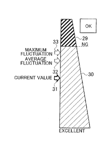
5 Examples of
images to be displayed on the display unit 5 in Step Sll and Step
SI3 shown in Fig. 6A will now be explained. First, Figs. 7A-7C show examples
of
images of a level gauge including two regions (29, 30), and first and second
arrows 31
and 32 which move in a longitudinal direction along the two regions (29, 30)
divided in
the longitudinal direction. The two regions includes a power-supply impossible
region
10 29 indicating a
region where the power cannot be supplied, and a power-supply possible
region 30 indicating a region where the power can be supplied. The boundary
between
the two regions (29, 30) indicates the minimum received voltage (minimum
allowable
voltage VO) that can be determined that the power can be supplied, if there is
no
fluctuation of the gap. In Fig. 7A, the first arrow 31 points the power-supply
impossible
15 region 29. The
first arrow 31 indicates the currently received voltage (NOW: first.
received voltage). Since the received voltage (NOW: first received voltage) is
lower
than the minimum allowable voltage VU, it is indicated that no wireless power
supply can
be executed, even in a case where it is as in the received voltage currently
measured, i.e.,
there is no fluctuation of the gap. That is, Fig. 7A shows an example of the
image
20 indicating "N.G. position" (improper position) displayed in Step S13
shown in Fig. 6A.
10049]
In Fig. 7B, the second arrow 32 in addition to the first arrow 31 is
displayed.
The second arrow 32 indicates a value (second reference value) obtained by
subtracting
the potential difference (Vgap) calculated at the time of the previous power
supply from
the currently received voltage (NOW: first received voltage). That is, it
indicates a
reference value of the received voltage in consideration of the gap
fluctuation value (Ore)
estimated on the basis of the previous power supplying operation. The interval
between
the first arrow 31 and the second arrow 32 indicates the potential difference
(Vgap)
calculated at the time of the previous power supply. The second arrow 32 is
moved to
the side of the power-supply impossible region 29 from the first arrow 31 only
by the
CA 03051815 2019-07-26
21
amount of the potential difference (Vgap).
[0050]
In Fig. 7B, although the first arrow 31 indicates the power-supply possible
region
30, the second arrow 32 indicates the power-supply impossible region 29.
Accordingly,
it can be present to the user that the power can be supplied if there is no
fluctuation of the
gap as remaining the received voltage (NOW) currently measured, but the power
cannot
be supplied in consideration of the gap fluctuation value estimated from the
previous
power supplying operation. Fig. 7B shows an example of an image indicating
N.G.
position" (improper position) displayed in Step S13 shown in Fig. 6A.
[0051]
In Fig. 7C both of the first arrow 31 and the second arrow 32 indicate the
power-
supply possible region 30. Fig. 7C shows an example of an image indicating
"O.K.
position" (proper position) displayed in Step Sll shown in Fig. 6A. It can be
presented
to the user that the power can be supplied even in consideration of the gap
fluctuation
value estimated from the previous power supplying operation.
[0052]
Thus, the parking assistance device according to the embodiments assists the
alignment between the coils by presenting the result of the comparison between
the
second reference value (second arrow 32) obtained by subtracting from the
currently
received voltage (NOW: first arrow 31) the potential difference (Vgap)
calculated at the
time of the previous power supply and the minimum allowable voltage (VO:
boundary
between the regions 29 and 30), to the occupant. Accordingly, the parking
assistance
device according to the embodiments can intelligibly present whether or not
the power
can be supplied.
[0053]
Next, Figs. 8A-8C show examples of images of a level gauge including four
regions (29, 30a, 30b, 30c), and a first arrow 31 which moves in a
longitudinal direction
along the four regions (29, 30a, 30b, 30e) divided into the longitudinal
direction. The
four regions includes a first power-supply impossible region 29, a second
power-supply
.. impossible regions 30a, a first power-supply possible regions 30b, and a
second power-
CA 03051815 2019-07-26
22
supply possible regions 30c. The first power-supply impossible region 29
indicates that
the power cannot be supplied even in a case where there is no fluctuation of
the gap as
remaining the received voltage (NOW) currently measured. The second power-
supply
impossible region 30a indicates that the power cannot be supplied, in
consideration of the
gap fluctuation value estimated from the previous power supplying operation.
The first
power-supply possible region 30b indicates that the power can be supplied, in
consideration of the gap fluctuation value estimated from the previous power
supplying
operation. The second power-supply possible region 30c indicates that the
power can
be supplied even in consideration of the maximum fluctuation range (Qmax) of
the gap.
The first arrow 31 indicates the currently received voltage (NOW: first
received voltage).
[0054]
In Fig. 8A, the first arrow 31 indicates the first power-supply impossible
region
29. Accordingly, it is presented to the user that the power cannot be
supplied even in a
case of remaining the received voltage (NOW) currently measured, i.e., in a
case where
there is no fluctuation of a gap. That is, Fig. SA shows an example of the
image
indicating "N.G. position" (improper position) in Step 513 shown in Fig. 6A.
[0055]
In Fig. 8B, the first arrow 31 indicates the second power-supply impossible
region 30a. Accordingly, it can be presented to the user that the power can be
supplied
if there is no fluctuation of the gap as remaining the received voltage (NOW)
currently
measured, but the power cannot be supplied in consideration of the gap
fluctuation value
estimated from the previous power supplying operation. That is, Fig. 8B shows
an
example of the image indicating "N.G. position" (improper position) in Step
S13 shown
in Fig. 6A.
[0056]
The boundary between the first power-supply impossible region 29 and the
second power-supply impossible region 30a indicates the minimum voltage
(minimum
allowable voltage VO) which can be determined that the power can be supplied,
if there
is no fluctuation of the gap. The boundary between the second power-supply
impossible
region 30a and the first power-supply possible region 30b indicates a value
(first reference
CA 03051815 2019-07-26
23
value) obtained by adding the potential difference (Vgap) calculated at the
time of the
previous power supplying operation to the minimum allowable voltage VU.
Accordingly, a width of the second power-supply impossible region 30a
indicates the
potential difference (Vgap) calculated at the time of the previous power
supply.
[0057]
In Fig. 8C, the first arrow 31 indicates the first power-supply possible
region 30b.
Accordingly, it can be presented to the user that the power can be supplied in
consideration of the gap fluctuation value estimated from the previous power
supplying
operation. That is, Fig. 8C shows an example of the image indicating ''O.K.
position"
(proper position) in Step S1.1 shown in Fig. 6A.
[0058]
Although illustration is omitted, if the first arrow 31 indicates the second
power-
supply possible region 30c, it can be presented to the user that the power can
be supplied
even if the same gap fluctuation as the maximum fluctuation range (Qmax) of
the gap
occurs.
[0059]
Thus, the parking assistance device assists the alignment between the coils by
presenting the result of the comparison between the currently received voltage
(NOW:
first arrow 31) and the first reference value (boundary between the regions
30a and 30b)
obtaining by adding the potential difference (Vgap) calculated at the time of
the previous
power supply to the minimum voltage (VO: boundary between the regions 29 and
30a)
which can be determined that the power can be supplied if there is no
fluctuation of the
gap, to the occupant. Accordingly, the parking assistance device according to
the
embodiments can intelligibly present whether or not the power can be supplied.
[0060]
With reference to Fig. 9, the received voltage (Vt1 third received voltage)
measured after the power supply will now be explained. The excitation for
detecting
coil position is started from the time T1 before stalling of the power supply,
and as the
vehicle 2 approaches, the received voltage (NOW) is also increased. The
vehicle
controller 4 measures the received voltage (V10) to be stored, from the time
T2 when the
CA 03051815 2019-07-26
24
vehicle 2 is stopped within the power-supply allowable range to the time 13
when the
excitation for detecting coil position is stopped.
[0061]
At the time when starting of the power supply or after a while after starting
of
the power supply, it is expected that the occupant gets down and/or the cargo
is unloaded
from the vehicle 2. As mentioned above, if the gap during executing the
alignment
between the coils before starting the power supply (i.e., gap before starting
power supply)
is different from the gap during supplying the power (i.e., gap during power
supply), the
power may be impossible to be properly supplied. Accordingly, in principle, it
is
preferable to calculate the potential difference on the basis of both of the
received voltage
(Vt0) measured before the power supply and the received voltage measured
during the
power supply.
[0062]
However, as shown in Fig. 9, at the time of the alignment before the power
supply,
the relay switch 9 is controlled to be turned off, and thereby the vehicle-
side coil 11 is
disconnected from the battery 10. On the other hand, since it is necessary to
transmit
the power to the battery 10 during the power supply, the relay switch 9 is
controlled to be
turned on, and thereby the vehicle-side coil 11 is connected to the battery
10.
Accordingly, the circuit configurations for measuring the received voltage are
different
between before the power supply and during the power supply. An impedance of
the
battery 10 largely affects the measurement of the received voltage, and
therefore the
received voltage is largely dependent on the voltage of the battery 10.
Moreover, since
the excitation performed during the power supply is stronger than the
excitation for
detecting coil position performed before the power supply and after the power
supply, the
received voltage to be measured is also increased. Accordingly, it is
difficult to measure
the received voltage on the same conditions before the power supply and during
the power
supply.
[0063]
Accordingly, the vehicle controller 4 starts the excitation for detecting coil
position again from the time 14 when a while has elapsed, after the power
supply is
CA 03051815 2019-07-26
completed and the battery 10 is electrically disconnected from the vehicle-
side coil 11.
The vehicle controller 4 measures the received voltage (Vtl) until the time TS
when the
excitation for detecting coil position is stopped. This is because it is
assumed that the
occupant has still got down and/or the cargo has still been unloaded from the
vehicle 2,
5 for a while
(T4-T5) after supplying the power for a sufficient long time. Moreover, since
the relay switch is controlled to be turned off, the circuit configurations
for measuring the
received voltage can be made equivalent before the power supply and after the
power
supply.
[0064]
10 As explained
above, according to the first embodiment, the following
operation/working-effects can be obtained. The fluctuation amount of the gap
can be
estimated from the potential difference (Vgap) between the received voltage at
the time
of the coil alignment which is previously obtained, and the received voltage
after
completing of the power supply. Accordingly, as shown in Figs. 4 and 5, it can
be
15 exactly
determined whether or not the power can be supplied, on the basis of the power-
supply allowable range (fil , H2) which is changed in accordance with the
fluctuation
amount of the gap, by determining the possibility of the power supplying on
the basis of
the potential difference (Vgap) and the received voltage (NOW). Moreover,
in
consideration of the amount of the gap fluctuation in the past, since the
possibility of
20 overestimating
the fluctuation range of the gap can be reduced, the power-supply
allowable range can be widely set, and thereby the convenience of the parking
can be
improved.
[0065]
(Second Embodiment)
25 The first embodiment has shown the example of assisting the coil
alignment at
the time of the next power supply in consideration of the gap fluctuation at
the time of
the previous power supply. That is, although the gap fluctuation to be
referred is only
one previous value in the first embodiment, the coil alignment may be assisted
in
consideration of a plurality of power supplying operations executed in the
past.
10066]
CA 03051815 2019-07-26
26
More specifically, before assisting the alignment between the coils, the
parking
assistance device previously measures and records a plurality of pairs of the
received
voltage before the power supply and the received voltage after the power
supply (second
received voltage Vt0, third received voltage Vt1). Then, when assisting the
alignment
between the coils, the average value (Vgap aye) of the plurality of pairs of
the potential
differences or the maximum value (Vgap max) of the plurality of pairs of the
potential
differences may be used as the potential difference (Vgap) previously
calculated.
Furthermore, it is also possible to simultaneously use the average value (Vgap
ave) and
the maximum value (Vgap max), as the potential difference (Vgap) previously
calculated.
[0067]
The parking assistance device according to the second embodiment assists the
alignment between the coils by presenting a possibility of the power supplying
determined by simultaneously using the average value (Vgap aye) and the
maximum
value (Vgap max) of the potential difference, to the occupant.
.. [0068]
First, the operation examples of before the power supply, during the power
supply, and after the power supply in the parking assistance device according
to the
second embodiment will now be explained, with reference to Figs. 11A-11C.
Among
the steps of Figs. 11A-11 C, the same step as the step of Figs. 6A-6C is
denoted by the
.. same reference sign, and the description thereof will be omitted.
[0069]
First, with reference to Fig. 11A, an operation at the time of the coil
alignment
before the power supply will now be explained. In Step S51, two voltage
thresholds
(Nith 1 and Vth2) are calculated by means of the average value (Vgap aye) and
the
maximum value (Vgap max) of the potential difference. More specifically, the
first
voltage threshold (Vthl ) is calculated by adding the average value (Vgap aye)
of the
potential difference to the threshold value (VU), and the second voltage
threshold (V1112)
is calculated by adding the maximum value (Vgap max) of the potential
difference to the
threshold value (V0).
[0070]
CA 03051815 2019-07-26
27
The average value (Vgap aye) and the maximum value (Vgap max) of the
potential difference are respectively the average value and the maximum value
of the
potential differences in a plurality of power supplying operations executed in
the past.
[0071]
In Step S53, the received voltage (NOW: first received voltage) are compared
with the first voltage threshold (Vthl ). In Step S55, the received voltage
(NOW) are
compared with the second voltage threshold (Vth2). If the received voltage
(NOW) is
equal to or higher than the first voltage threshold (Vt.h1) and is equal to or
higher than the
second voltage threshold (Vth2) (YES in S55), a green signal is turned on the
display unit
5 (LED). If the received voltage (NOW) is equal to or higher than the first
voltage
threshold (Vthl) and is lower than the second voltage threshold (Vth2) (NO in
S55), a
yellow signal is turned on the display unit 5 (LED). If the received voltage
(Vt0) is
lower than the first voltage threshold (Vth ) (NO in S53), a red signal is
turned on the
display unit 5 (LED). Although illustration is omitted, the display unit 5
according to
the second embodiment includes not the display configured to display the level
gauge but
at least the LED configured to emit light in red, the LED configured to emit
light in yellow,
and the LED configured to emit light in green. Such LEDs are mounted on a
position
where the user (occupant) can visually recognize, e.g., a dashboard of the
vehicle 2.
[0072]
If the red signal is turned on, it can be presented to the occupant that the
power
cannot be supplied in consideration of the average value (Vgap ave) of the
potential
difference. That is, it can be presented to the occupant that the center lie
of the vehicle-
side coil 11 cannot be kept within the power-supply allowable range 21 if the
gap
fluctuation equal to or greater than the average value of the gap fluctuation
in the past
occurs.
[0073]
If the yellow signal is turned on, it can be presented to the occupant that
the
power can be supplied in consideration of the average value (Vgap aye) of the
potential
difference, but no power can be supplied in consideration of the maximum value
(Vgap_max) of the potential difference. That is, it can be presented to the
occupant that
CA 03051815 2019-07-26
28
the center lie of the vehicle-side coil 11 can be kept within the power-supply
allowable
range 21 if the gap fluctuation equal to or less than the average value of the
gap fluctuation
in the past occurs. Moreover, if the gap fluctuation equal to or greater than
the average
value of the gap fluctuation in the past and equal to or less than the maximum
value of
the gap fluctuation in the past occurs, it can be presented to the occupant
that the center
Ilc of the vehicle-side coil 11 will be deviated from the power-supply
allowable range
21.
[0074]
If the green signal is turned on, it can be presented to the occupant that the
power
can be supplied in consideration of the average value (Vgap_ave) and the
maximum value
(Vgap_max) of the potential differences in the plurality of the power
supplying operations
executed in the past. That is, it can be presented to the occupant that the
center lie of
the vehicle-side coil 11 can be kept within the power-supply allowable range
21 even if
the gap fluctuation equal to the maximum value of the gap fluctuation in the
past occurs.
[0075]
With reference to Fig 11B and 11C, an operation during the power supply and an
operation after the power supply will now be explained. In Step S63, the
vehicle
controller 4 determines whether or not the power supply time is equal to or
longer than
30 minutes, if there is no request to stop the electrically charging from the
user (NO in
S31). If the power supplying operation is less than 30 minutes, since the
occupant does
not yet get off and the cargo is still loaded during supplying the power,
there is a
possibility that no gap fluctuation occurs. Accordingly, it is not necessary
to measure
the received voltage (Vtl) after the power supply. Accordingly, the vehicle
controller 4
executes the request 10 confirm position after the power supply by means of
the wireless
communication device 6 only when the power is supplied for a sufficient long
time (YES
in S65).
[0076]
Then, the vehicle controller 4 measures the received voltage (Vtl) only when
the
request to confirm position after power the supply is executed in Step S67
shown in Fig.
11C. Consequently, the received voltage at the time of the power supplying
operation
CA 03051815 2019-07-26
29
in which no gap fluctuation occurs (Vt1) can be removed from the calculation
of the
average value (Vaap_ave). The noise is removed and thereby the computation
accuracy
of the average value (Vgap aye) of the potential difference cab be improved.
[0077]
Furthermore it is determined whether or not the IGN switch remains to be
turned
off, for a predetermined time after the power supply is completed (e.g., for 3
minutes)
(S69 to S73). If the IGN switch is turned on during the predetermined time
after the
power supply is completed, it is estimated that the occupant already gets on
and/or the
cargo is loaded thereon at the time of completing of the power supply.
Accordingly, the
received voltage (Vtl) is measured only when the IGN switch remains to be
turned off
(YES in S73) for a predetermined time after the power supply is completed
(e.g., for 3
minutes). Consequently, the received voltage at the time of the power
supplying
operation in which no gap fluctuation occurs (Vtl) can be removed from the
calculation
of the average value (Vgap_ave). The noise is removed and thereby the
computation
accuracy of the average value (Vgap aye) of the potential difference cab be
improved.
[0078]
Whether or not the maximum value (Vgap max) is updated is confirmed based
on the potential difference (Vgap) calculated in step S51 (S75, S77).
Moreover, in Step
S79, the average value (Vgap aye) is updated on the basis of the potential
difference
(Vgap).
[0079]
As explained above, according to the second embodiment, the following
operation/working-effects can be obtained. Before assisting the alignment
between the
coils, the vehicle controller 4 previously measures and records a plurality of
pairs of the
received voltage before the power supply and the received voltage after the
power supply
(second received voltage Vt0, third received voltage VII). Then, the vehicle
controller
4 assists the alignment between the coils by suing the average value (Vgap
aye) of the
plurality of pairs of the potential differences or the maximum value (Vgap
max) of the
plurality of pairs of the potential differences may be used as the potential
difference
(Vgap) previously calculated, when assisting the alignment between the coils.
CA 03051815 2019-07-26
Consequently, the fluctuation amount of the gap when assisting the alignment
between
the coils can be predicted with sufficient accuracy.
[0080]
(Modified Example)
5 The modified
example of the second embodiment will now explain an example
of displaying an image indicating "N.G. position" (improper position) or an
image
indicating "O.K. position" (proper position) by means of a display mounted on
the
dashboard of the vehicle 2, in a similar manner to the first embodiment,
instead of the
display unit 5 (LEDs).
10 [0081]
Examples of images to be displayed on the display unit 5 in Steps S57, S59,
and
S61 shown in Fig. 11A will now be explained. First, Figs. 12A-12C show
examples of
images of a level gauge including two regions (29, 30), and first to third
arrows 31, 32,
and 33 which move in a longitudinal direction along the two regions (29, 30)
divided in
15 the
longitudinal direction. The two regions includes a power-supply impossible
region
29 indicating a region where the power cannot be supplied, and a power-supply
possible
region 30 indicating a region where the power can be supplied. The boundary
between
the two regions (29, 30) indicates the minimum received voltage (minimum
allowable
voltage VO) that can be determined that the power can be supplied, if there is
no
20 fluctuation of
the gap. The first arrow 31 indicates the currently received voltage
(NOW: first received voltage). The second arrow 32 indicates a value (second
reference
value) obtained by subtracting the average value (Vgap_ave) of the potential
difference
from the currently received voltage (NOW: first received voltage). The third
arrow 33
indicates a value (third reference value) obtained by subtracting the maximum
value
25 (Vg,ap max) of the potential difference from the currently received
voltage (NOW: first
received voltage). That is, the second arrow 32 and the third arrow 33
respectively
indicate the received voltages in consideration of the average value and the
maximum
value of gap fluctuation which are respectively estimated from the plurality
of the power
supplying operations in the past. The interval between the first arrow 31 and
the second
30 arrow 32
indicates the average value (Vgap _aye) of the potential difference. The
CA 03051815 2019-07-26
31
interval between the first arrow 31 and the third arrow 33 indicates the
maximum value
(Vgap max) of the potential difference.
[0082]
In Fig. I2A, the first arrow 31 points the power-supply possible region 30,
and
the second arrow 32 and the third arrow 33 point the power-supply impossible
region 29.
Accordingly, it can be presented to the user that the power can be supplied if
there is no
fluctuation of the gap as remaining the received voltage (NOW) currently
measured, but
the power cannot be supplied in consideration of the average value and the
maximum
value of the gap fluctuations respectively estimated from the plurality of the
power
supplying operations in the past. Fig. 12A corresponds to the lighting-on
state of the red
signal in Step S57 shown Fig. 11A.
[0083]
In Fig. 1213, each of the first arrow 31 and the second arrow 32 points the
power-
supply possible region 30, and the third arrow 33 points the power-supply
impossible
region 29. Consequently, according to the display image shown in Fig. 12B, it
can be
presented to the user that the power can be supplied even if the gap
fluctuation equal to
or less than the average value of gap fluctuation occurs, but no power can be
suppled if
the gap fluctuation equal to or greater than the average value of the gap
fluctuation occurs.
Fig. 12B corresponds to the lighting-on state of the yellow signal in Step S59
shown Fig.
HA.
[0084]
In Fig. 12C, all the first arrows 31, the second arrows 32, and third arrows
33
point the power-supply possible region 30. Consequently, according to the
display
image shown in Fig. 12C, it can be presented to the user that the power can be
supplied
even if the same gap fluctuation as the maximum value of the gap fluctuations
respectively estimated from the plurality of the power supplying operations in
the past
occurs. Fig. 12C corresponds to the lighting-on state of the green signal in
Step S6 l
shown Fig. 11A.
[0085]
Thus, the parking assistance device assists the alignment between the coils by
CA 03051815 2019-07-26
32
presenting the result of the comparison between the second reference value
(the second
arrow 32 and the third arrow 33) obtained by respectively subtracting the
average value
(V vap_ave) and the maximum value (Vgap_max) of the potential difference from
the
currently received voltage (first arrow 31) and the minimum received
voltage(VO:
boundary between the regions 29 and 30) that can be determined that the power
can be
suppled if there is no fluctuation of the gap, to the occupant. Accordingly
the parking
assistance device according to the embodiments can intelligibly present
whether or not:
the power can be supplied.
[0086]
Next, Figs. 13A-13C show examples of images of a level gauge including four
regions (29, 34, 35, 36), and a first arrow 31 which moves in a longitudinal
direction
along the four regions (29, 34, 35, 36) divided into the longitudinal
direction. The four
regions includes a first power-supply impossible region 29, a second power-
supply
impossible regions 34, a first power-supply possible regions 35, and a second
power-
supply possible regions 36. The first power-supply impossible region 29
indicates that
the power cannot be supplied even in a case where there is no fluctuation of
the gap as
remaining the received voltage (NOW) currently measured. The second power-
supply
impossible region 34 indicates that the power cannot be supplied, in
consideration of the
average value of the gap fluctuations estimated from the plurality of the
power supplying
operations in the past. The first power-supply possible region 35 indicates
that the
power can be supplied in consideration of the average value of gap
fluctuations, but no
power can be supplied in consideration of the maximum value of the gap
fluctuations in
the plurality of the power supplying operations in the past. The second power-
supply
possible region 36 indicates that the power can be supplied even in
consideration of the
maximum of the gap fluctuations.
[0087]
The boundary between the first power-supply impossible region 29 and the
second power-supply impossible region 34 indicates the minimum allowable
voltage VO.
The boundary between the second power-supply impossible region 34 and the
first power-
supply possible region 35 indicates the value (first reference value) obtained
by adding
CA 03051815 2019-07-26
33
the average value (Vgap_ave) of the potential difference to the minimum
allowable voltage
VO. The boundary between the first power-supply possible region 35 and the
second
power-supply possible region 36 indicates the value (first reference value)
obtained by
adding the maximum value (Vgap_max) of the potential difference to the minimum
allowable voltage VO.
[0088]
In Fig. 13A, the first arrow 31 points the second power-supply impossible
region 34.
Fig. 13A presents the user that the power can be suppled in a case where it is
as in the received
voltage (NOW) currently measured, but no power can be suppled if the gap
fluctuation which
is the average value (Vgap_ave) of the potential difference occurs. Fig. 13A
corresponds to
the lighting-on state of the red signal in Step S57 shown Fig. 11A.
[0089]
In Fig. 13B, the first arrow 31 points the first power-supply possible region
35. Fig.
13B presents the user that the power can be supplied even if the gap
fluctuation which is the
average value (Vgap_ave) of the potential difference occurs, but no power can
be supplied if
the gap fluctuation which is the maximum value (Vgap max) of the potential
difference occurs.
Fig. 13B corresponds to the lighting-on state of the yellow signal in Step S59
shown Fig. 11A.
[0090]
In Fig. 13C, the first arrow 31 points the second power-supply possible region
36.
Fig. 13C presents the user that the power can be supplied even if the gap
fluctuation which is
the maximum value (Vgap_max) of the potential difference occurs. Fig. 13C
corresponds to
the lighting-on state of the green signal in Step S61 shown Fig. 11A.
[0091]
Thus, the parking assistance device assists the alignment between the coils by
presenting the result of the comparison between the currently received voltage
(NOW:
first arrow 31) and the first reference value (boundary between the regions 34
and 35)
obtained by adding the average value (Vgap_ave) of the potential difference to
the
minimum received voltage (VO: boundary between the regions 29 and 34) that can
be
CA 03051815 2019-07-26
34
determined that the power can be supplied if there is no fluctuation of the
gap, to the
occupant. Accordingly, the parking assistance device according to the
embodiments can
intelligibly present whether or not the power can be supplied.
[0092]
The parking assistance device assists the alignment between the coils by
presenting the result of the comparison between the currently received voltage
(NOW:
first arrow 31) and the first reference value (boundary between the regions 35
and 36)
obtained by adding the maximum value (Vgapmax) of the potential difference to
the
minimum received voltage (VO: boundary between the regions 29 and 34) that can
be
deteimined that the power can be supplied if there is no fluctuation of the
gap, to the
occupant. Accordingly, the parking assistance device according to the
embodiments can
intelligibly present whether or not the power can be supplied.
[0093]
Although the foregoing descriptions have been provided for the contents of the
present invention on the basis of the embodiments, the present invention is
not limited to
what have been described, and it is obvious to those skilled in the art that
various
modifications and improvements can be made to the present invention.
[0094]
As shown in Fig. 10, in the first and second embodiments, the time period 43
for
executing the parking assistance except for first-time is simultaneously the
time period
41 for measuring the received voltage (Vt0: second received voltage). The
present
invention is not limited to this example. That is, only when selected by the
user, the
received voltage (i.e., the second received voltage Vt0, the third received
voltage Vtl)
may be measured. For example, a mode selection switch for switching ON/OFF of
an
estimation mode for estimating the gap fluctuation value is provided on a
dashboard.
Only when the mode selection switch is operated by the user and thereby the
estimation
mode is set to ON, the received voltage (the second received voltage Vt0, the
third
received voltage VU) may be measured and stored.
Consequently, in the first
embodiment, the possibility of power supplying is determined on the basis of
the latest
potential difference in the potential differences (Vgap) detected in a state
where the
CA 03051815 2019-07-26
estimation mode is in ON state. In the second embodiment, the possibility of
power
supplying is determined on the basis of the average value (Vgap_ave) and the
maximum
value (Vgap_max) calculated by using all the potential differences (Vgap)
detected in a
state where the estimation mode is in ON state. Accordingly, since the user
oneself can
5 determine the estimated value of the gap fluctuation used at the time of
the parking
assistance in accordance with the utilization situation of the vehicle 2, user
convenience
can be improved.
[0095]
The parking assistance device (control unit) can be realized by means of a
10 microcomputer including a central processing unit (CPU), a memory. and
an input and
output unit. A computer program for functioning the microcomputer as the
parking
assistance device is installed in the microcomputer in order to be executed
therein.
Thereby, such a microcomputer can be functioned as the parking assistance
device.
Although the example of realizing the parking assistance device by means of
software is
15 shown herein, it is naturally also possible to prepare hardware for
exclusive use for
executing each information processing shown hereinafter to configure to the
parking
assistance device. Moreover, a plurality of circuits included in the parking
assistance
device may be configured with individual hardware.
Furthermore, the parking
assistance device may also serve as an electronic control unit (ECU) used for
other control
20 in connection with the vehicle. The vehicle controller 4 (control unit)
shown in Fig. 1
is exemplified as such an electronic control unit (ECU) used for other control
in respect
of the vehicle 2.
REFERENCE SIGNS LIST
25 [0096]
Vehicle
4 Vehicle controller (control unit)
8 Current/voltage sensor (voltage sensor)
11 Vehicle-side coil (receiving coil)
30 12 Ground-side coil (power transmission coil)
CA 03051815 2019-07-26
36
32 Second arrow (second reference value)
33 Third arrow (second reference value)
NOW First received voltage
Vgap Potential difference
Vgap ave Average value of potential difference
Vgap_max Maximum value of potential difference
Vt0 Second received voltage
Vtl Third received voltage
VO Minimum allowable voltage