Note: Descriptions are shown in the official language in which they were submitted.
- 1 -
Wire netting and method for manufacturing a helix for a wire netting
State of the art
The present invention refers to a wire netting and a method for manufacturing
a
helix for a wire netting.
From the state of the art wire nettings are known having wire helices which
are
braided with each other. Such wire helices are produced by repeatedly bending
of a
wire in a bending direction and have a helical profile. The bending is
effected by
means of a bending table, which bends the wire about a bending mandrel. The
wire
.. is obliquely supplied to the bending mandrel by means of suitable supply
rollers,
which guide the wire along its longitudinal sides.
The object of the invention is in particular to provide a generic wire netting
with
advantageous properties with regard to load-bearing capacity.
Advantages provided by the invention
The invention is based on a wire netting, in particular a safety net, with a
plurality of helices which are braided with each other, of which at least one
helix is
bent from at least one single wire, a wire bundle, a wire strand, a wire rope
and/or
another longitudinal element with at least one wire, which in particular
comprises a
zo .. high-tensile steel, and comprising at least one first leg, at least one
second leg as
well as at least one bending region connecting the first leg and the second
leg to
each other.
It is proposed that the longitudinal element, in particular the wire, is bent
at least
substantially torsion-free in itself or is bent without any torsion along a
contour of the
first leg and/or of the second leg.
Due to the inventive configuration of the wire netting, it is in particular
possible
to obtain a high load-bearing capacity. Advantageously, a wire netting having
a high
tensile strength may be provided. Moreover, cracks in the mesh, such as those
due
to impacting objects, may be reduced. Furthermore, a strength of a wire used
for
CA 3052089 2019-11-27
CA 03052089 2019-07-30
- 2 -
manufacturing may be maintained, at least to a large extent. In particular, a
tensile
strength and/or a fragility and/or a flexural rigidity and/or fracture
resistance of the
wire used for manufacturing can be modified only to an irrelevant extent or at
least
only partially in manufacturing. A frequency of wire fractures may be
advantageously
reduced during manufacturing of a high-tensile wire netting or the wire
fractures may
be entirely avoided. Moreover, manufacturing inaccuracies due to material
irregularities and/or internal stresses may be reduced.
In this context, a "wire" is in particular to be understood as a longitudinal
and/or
thin and/or at least machine-bendable and/or bendable body. The wire
advantageously has along its longitudinal direction a cross section which is
at least
essentially constant, in particular a circular or elliptical cross section. A
particularly
preferred wire is a round wire. It may however also be conceived that the wire
is at
least section-wise or entirely implemented as a flat wire, a square wire, a
polygonal
wire and/or a profiled wire. The wire may be made, for example, at least
partially or
also entirely of metal, in particular a metal alloy, and/or an organic and/or
inorganic
plastic and/or a composite material and/or an inorganic non-metallic material
and/or a
ceramic material. It is conceivable, for example, that the wire is a polymeric
wire or a
plastic material wire. In particular, the wire may be a composite wire, such
as a
metallic-organic composite wire and/or a metallic-inorganic composite wire
and/or a
metallic-polymeric composite wire and/or a metal-metal composite wire or
similar. In
particular it may be considered that the wire comprises at least two different
materials, which in particular are arranged relatively to each other according
to a
composite geometry and/or which are at least partially mixed with each other.
The
wire is advantageously embodied as a metal wire, in particular a steel wire,
in
.. particular a stainless-steel wire. If the helix has a plurality of wires,
these are
preferably identical. It may also be that the helix has a plurality of wires,
which differ
in particular regarding their material and/or their diameter and/or their
cross section.
The wire has preferably a coating, in particular corrosion-resistant, and/or a
jacket
such as a zinc coating and/or an aluminum-zinc-coating and/or a plastic
coating
and/or a PET-coating and/or a metal-oxide coating and/or a ceramic coating or
similar. The longitudinal element is preferably the wire.
The transversal extension of the helix is longer, in particular much longer
than a
diameter of the wire and/or a diameter of the longitudinal element of which
the helix
CA 03052089 2019-07-30
- 3 -
is implemented. Depending on the application and in particular a desired load-
bearing capacity and/or desired spring characteristics of the wire netting, in
particular
in a frontal direction, the transversal extension may, for example, be two
times or
three or five or ten or 20 times the diameter of the longitudinal element,
wherein
intermediate values or smaller values or larger values are conceivable.
Moreover,
depending on an application, the wire may have a diameter of, for example,
about 1
mm, about 2 mm, about 3 mm, about 4 mm, about 5 mm, about 6 mm, about 7 mm
or even more or even less or also an intermediate diameter value. Larger, in
particular much larger diameters are also conceivable if the longitudinal
element
1.0 comprises a plurality of components, in particular a plurality of
wires, such as, for
example, in case of a wire rope or a strand or a wire bundle or similar. By a
"main
extension plane" of an object is in particular a plane to be understood which
is
parallel to a largest side surface of the smallest theoretical rectangular
cuboid which
is just completely enveloping the object, and in particular extends through
the center
point of the rectangular cuboid.
In particular, the wire netting is configured as a slope protection, a safety
fence,
a guard fence, a protective net against rockfall, a blocking fence, a fish
farming net, a
safety net against predators, a corral fence, a tunnel safeguarding, a
protection from
earth flows, a protection fence for motor sports, a street fence, an avalanche
protection or similar. In particular, due to its high-tensile and/or load-
bearing capacity,
applications may be envisaged as a cover and/or envelope, for example for
power
plants, factory buildings, residential buildings or other buildings, for
explosion
protection, bullet proofing, shielding against flying objects, fishing nets,
collision
protection or similar. The wire netting may for example be applied, deployed
and/or
positioned and/or mounted horizontally or vertically or obliquely, in
particular with
respect to a ground. The wire netting is in particular embodied planar. The
wire
netting is advantageously constructed in a regular and/or periodical way, at
least in
one direction. The wire netting may be preferably rolled up or out, in
particular about
an axis, which is parallel to the main extension direction of the helix. In
particular, a
rolled-up roll of wire netting may be rolled out in a direction perpendicular
to the main
extension direction of the helix.
The wire netting preferably has a plurality of in particular identical meshes.
The
helices especially advantageously form the meshes.
CA 03052089 2019-07-30
- 4 -
Preferably, the helix has a spiral shape. In particular, the helix is embodied
as a
flattened spiral. The helix is provided along its contour with a diameter
and/or cross-
section which is at least essentially constant or is constant. The helix
and/or the wire
and/or the longitudinal element have a circle-shaped cross-section.
Particularly
preferably the helix has a plurality of legs, which are advantageously
implemented at
least substantially identical or are identical. The helix is preferably
composed of a
single, in particular continuous, wire.
"At least substantially identical" objects is in particular to mean, in this
context,
objects which are configured in such a way that they are respectively capable
of
fulfilling a common function and which differ in their construction, except
for
manufacturing tolerances, at most by single elements, which are irrelevant for
the
common function. Preferably, "at least substantially identical" means that
they are
identical, except for manufacturing tolerances and/or in the context of
manufacturing
possibilities. An "at least substantially constant value" in particular means,
in this
context, a value which varies at most by 20%, advantageously at most 15%, in
particular at most 10%, preferably at most 5% and in particular at most 2%. An
object
having an "at least substantially constant cross section' is in particular to
mean that
for an arbitrary first cross section of the object along at least one
direction and an
arbitrary second cross section of the object along the direction, a minimum
surface
area of a difference surface, which is formed by overlapping the cross
sections, is at
most 20%, advantageously at most 10% and especially advantageously at most 5%
of the surface area of the larger of the two cross sections.
In particular, the helix has a longitudinal direction. Preferably, the
longitudinal
direction of the helix is arranged at least substantially parallel or parallel
to a main
extension direction of the helix. Preferably, the helix has a longitudinal
axis extending
parallel to the longitudinal direction of the helix. Preferably, the main
extension plane
of the helix is arranged at least substantially parallel to the main extension
plane of
the wire netting, at least in a planarly unfolded and/or planarly rolled-out
state of the
wire netting, which may in particular differ from an installed state of the
wire netting.
A "main extension direction" of an object is intended to mean, in particular,
a direction
which runs parallel to a longest edge of a smallest imaginary rectangular
cuboid,
which just still completely encloses the object. "At least substantially
parallel" should
mean in particular an orientation of a direction relative to a reference
direction, in
CA 03052089 2019-07-30
- 5 -
particular in a plane, wherein the direction has a deviation relative to the
reference
direction, which is in particular less than 8 , advantageously less than 5
and
particularly advantageously less than 2 .
Preferably, the wire netting has a plurality or a multiplicity of, in
particular at
least substantially identically formed or in particular identically, formed
helices. It is
also conceivable that the wire netting is composed of several different
helices. In
particular, it is conceivable that the wire netting has a plurality or
multiplicity of first
helices and a plurality or multiplicity of second helixes of different
construction with
respect to the first helices, which are in particular arranged alternately.
The helices
are advantageously connected to each other. In particular, adjacent helices
are
arranged such that their longitudinal directions are parallel. Preferably, a
respective
helix is braided and/or twisted into two helices which are adjacent to said
helix. In
particular, the wire netting is producible by twisting a helix into a pre-
netting, twisting
a further helix into this twisted-in helix, twisting a helix into this further
twisted-in helix
in turn, and so on. In particular, the helices of the wire netting have the
same
direction of rotation. Advantageously, in each case two helices are knotted
with one
another, in particular respectively at a first of their ends and/or
respectively at a
second of their ends situated opposite their first ends.
Preferably, a torsional state of the longitudinal element, in particular of
the wire,
in the helix corresponds to a torsional state of the longitudinal element, in
particular
of the wire, before a bending of the longitudinal element, in particular of
the wire, to
form the helix. In particular, the longitudinal element, in particular the
wire, is twisted
in itself in particular about its longitudinal axis along a section of the
helix which
comprises at least three bending regions, advantageously at least four bending
regions, more preferably at least 5 bending regions, preferably at least 10
bending
regions, more preferably at least 15 bending regions and in a particularly
preferable
case at least 20 bending regions, by less than a complete rotation. In
particular, the
longitudinal element is twisted in itself along a section of the helix which
comprises a
certain number of bending regions, by an angle which is smaller,
advantageously at
least twice smaller, especially advantageously at least three times smaller,
preferably
at least five times smaller and especially advantageously at least ten times
smaller
than a sum of all bending angles of all bending regions of the section.
Preferably, the
longitudinal element, in particular the wire, has a smaller torsion than the
one a
CA 03052089 2019-07-30
- 6 -
longitudinal element would have in the case of a bending of bending regions,
in
which the longitudinal element to be bent is retained in such a way that a
rotation
about its longitudinal axis is prevented.
In particular, the wire is at least partially, in particular entirely except
for a
coating, made of high-tensile steel. For example, the high-tensile steel may
be spring
steel and/or a steel suitable for wire ropes. In particular, the wire has a
tensile
strength of at least 800 N mm-2, advantageously at least 1000 N mm-2,
especially
advantageously at least 1200 N mm-2, preferably of at least 1400 N mm-2, and
more
preferably at least 1600 N mm-2, in particular a tensile strength of about
1770 N mm-2
3.o or of about
1960 N mm-2. It is also conceivable that the wire has an even higher
tensile strength, for example a tensile strength of at least 2000 N mm-2, or
of at least
2200 N mm-2, or even at least 2400 N mm-2. In this way, a high load-bearing
capacity,
in particular a high tensile strength and/or a high rigidity are achievable
transversally
to the mesh.
In an advantageous embodiment of the invention it is proposed that the
longitudinal element, in particular the wire, is bent, at least substantially
without any
torsion in itself or without any torsion in itself, along a contour of the
bending region.
In particular the longitudinal element, in particular the wire, is bent, at
least
substantially without any torsion in itself or without any torsion in itself,
along a
contour of the helix. The helix is advantageously free of torsion. The wire
netting is
preferably braided from helices which are bent without torsion. In this way, a
durable
connection may be advantageously established between adjacent helices of a
wire
netting. Moreover, in this way, breakage in the area of bending regions may be
avoided.
In a particularly preferred embodiment of the invention it is proposed that a
surface structure of the first leg and/or of the second leg has a preferential
direction
which is parallel to a main extension direction of the first leg and/or of the
second leg.
The first leg and/or the second leg advantageously have at least one surface
structure element extending parallel to the main extension direction of the
first leg
and/or of the second leg. For example, the surface structure element may be
embodied as a ridge, in particular of less than 50 pm, preferably less than 20
pm and
particularly advantageously of less than 10 pm, and/or as a region of material
disposed on a wire surface and/or as a surface texture. In particular, the
surface
CA 03052089 2019-07-30
- 7 -
structure comprises a plurality of surface structure elements. Advantageously
a
plurality of surface structure elements extends at least substantially
parallel or
parallel to the main extension direction of the first leg and/or of the second
leg. In
particular, the preferential direction is equivalent to an average direction
of individual
contours of the surface structure elements. In particular, the coating of the
wire
implements the surface structure. It may also be conceived that the wire is
not coated
and implements the surface structure. In this way, a high tensile strength may
be
achieved.
Moreover, it is proposed that the surface structure of the first leg and/or of
the
second leg is free from partial structures extending spirally and/or helically
with
respect to the main extension direction of the first leg and/or second leg, in
particular
rotating and/or winding about the longitudinal direction of the helix. In this
way, a
breaking or rupturing of a wire netting in the area of a leg may be avoided.
Moreover, it is proposed that, in a transverse view, parallel to a main
extension
plane of the helix and perpendicularly to a longitudinal direction of the
helix, the
bending region at least section-wise follows an at least approximately
straight
contour, in particular a straight contour. "At least approximately straight"
is in
particular to mean, in this context, straight, preferably linear, within
manufacturing
tolerances. Preferably in the transversal view a section of the bending region
follows
the at least approximately straight or straight contour, wherein this section
comprises
at least 50%, advantageously at least 75% and particularly advantageously at
least
85% of the bending region. The bending region is curved in the section, in
particular
in an area of the bending region, in a plane which is parallel to the
approximately
straight contour of the bending region. In the frontal view, the approximately
straight
contour preferably is at least substantially parallel or parallel to the
longitudinal
direction of the helix. This allows providing a bending region with a high
tensile
strength and/or with a high flexural rigidity. Furthermore, this allows a
favorable
geometry with regard to a connecting of bending regions of different helices.
It is also proposed that, in the transverse view, the helix follows at least
section-
wise a stepped, in particular obliquely stepped contour. Preferably, the first
leg, the
bending region and the second leg in the transverse view form the stepwise
contour,
wherein the bending region or at least its approximately straight contour
includes with
the first leg and/or with the second leg an angle which is equivalent to a
gradient
CA 03052089 2019-07-30
- 8 -
angle of the bending region.
A high stability of a wire netting transversally to its surface can be
achieved if
the first leg and/or the second leg at least section-wise follow a straight
contour.
Advantageously, the first leg and the second leg form straight sides of a mesh
of the
wire netting. Particularly advantageously the entire first leg and/or the
entire second
leg are embodied straight. In particular, the first leg and/or the second leg
have a
length of at least 1 cm, advantageously of at least 2 cm, particularly
advantageously
of at least 3 cm, preferably of at least 5 cm and particularly preferably of
at least 7
cm. However, the first leg and the second leg can have any other lengths, in
particular considerably greater lengths. For example, the first leg and/or the
second
leg may have a length of at least 10 cm or at least 15 cm or at least 20 cm or
at least
25 cm or an even greater length, especially in a case where the helix is
embodied as
a strand of wire, a wire rope, a wire bundle or similar.
In a further embodiment of the invention, it is proposed that the first leg
runs at
least section-wise in a first plane and the second leg extends at least
section-wise in
a second plane that is parallel to the first plane. In particular, at least
two adjacent
legs of the helix extend in parallel planes. Advantageously, the first leg
extends in the
transverse view parallel to the second leg. Preferably, the first leg and the
further first
leg extend in the first plane and/or the second leg and the further second leg
extend
in the second plane. Preferably, the first plane defines a front side of the
wire netting
and/or the second plane defines a rear side of the wire netting or vice versa.
As a
result, a wire netting with a double-surface and/or a double-walled structure
can be
provided. Preferably, forces acting transversely to the mesh can thereby be
effectively accommodated with minimal deformation of the mesh.
Furthermore, the invention refers to a method for manufacturing a helix for a
wire netting, in particular for a safety net, wherein the helix is bent from
at least one
single wire, a wire bundle, a wire strand, a wire rope and/or another
longitudinal
element with at least one wire, which in particular comprises a high-tensile
steel, in
such a way that it comprises at least one first leg, at least one second leg
as well as
at least one bending region connecting the first leg and the second leg to
each other.
It is proposed that the longitudinal element, in particular the wire, is at
least
substantially bent, without any torsion in itself, along a contour of the
first leg and/or
of the second leg.
CA 03052089 2019-07-30
- 9 -
With the inventive method, advantageous properties related to load-bearing
capacity of a wire netting may be achieved. Advantageously a wire netting may
be
provided with a high tensile strength. Moreover, fractures in the mesh, such
as those
caused by impacting objects, may be reduced. Moreover, a strength of a wire
used
for manufacturing can be maintained, at least for the most part. In
particular, in
manufacturing a tensile strength and/or fragility and/or flexural rigidity
and/or break
resistance of a wire used for manufacturing are only slightly or at least only
partially
modified. Wire ruptures may be avoided or at least reduced in manufacturing of
high-
tensile wire nettings. Moreover, manufacturing errors due to material stresses
may
be reduced.
The longitudinal element, in particular the wire, is bent by means of at least
one
bending device. Particularly preferably, the bending device has at least one
bending
table. The bending device has at least one bending mandrel, about which during
a
bending the longitudinal element, in particular the wire, is bent, in
particular by the
bending table. The wire is preferably supplied to the bending mandrel under an
angle
which is different from 900 and which is in particular equivalent to a
gradient angle of
the first leg with respect to the longitudinal direction of the helix.
In particular, the method is provided for manufacturing the wire netting. The
method preferably comprises a step for producing and/or implementing at least
one
of the features of the wire netting. "Provided" should in particular mean,
specifically
programmed, designed and/or equipped. The fact that an object is provided for
a
certain function is in particular intended to imply that the object fulfills
and/or performs
this function in at least one application and/or operating state. The fact
that a method
is "provided" for a certain purpose is in particular to mean that the method
contains at
least one method step which is specifically directed to the purpose, and/or
that the
method is specifically directed to the purpose, and/or that the method serves
to fulfill
the purpose and is at least partially optimized for said fulfilment.
The fact that a method step is "provided" for a purpose is in particular to
mean
that the method step is specifically directed to the step, and/or that the
method step
.. is specifically targeted at the purpose, and/or that the method step serves
to fulfill the
purpose and is at least partially optimized toward said fulfilment.
It is also proposed that the longitudinal element, in particular the wire, is
supplied to the bending device for bending, wherein the longitudinal element,
in
CA 03052089 2019-07-30
- 10 -
particular the wire, during supply is rotated about its longitudinal axis.
Preferably a
rotation direction of the longitudinal element, in particular the wire, during
supply, is
equivalent to a sense of rotation of the helix. In particular, the
longitudinal element, in
particular the wire, is rotated about its longitudinal axis in such a way that
a torsion
occurring during bending about the bending mandrel is compensated. Thus, a
twisting of a wire during a bending of a helix may be advantageously avoided.
Moreover, it is proposed that the longitudinal element, in particular the
wire,
passes through a rotating orienting apparatus. The orienting apparatus is
rotated
about the longitudinal axis of the longitudinal element, in particular the
wire, in
particular with a rotation speed, which is in particular at least
substantially equivalent
to a rotation speed of the longitudinal element, in particular the wire, about
its
longitudinal axis. Preferably the orienting apparatus is supported rotatably
about the
longitudinal axis of the longitudinal element, in particular the wire. Thus, a
high
manufacturing precision at high throughput may be achieved.
In a preferred embodiment of the invention it is proposed that the
longitudinal
element, in particular the wire, is unwound from a co-rotated reel. The reel
is
preferably supported rotatably about an unwinding axis. Especially
advantageously
the reel, in particular an unwinding bearing of the reel, is supported
rotatably about a
rotation axis. In particular, the rotation axis of the reel is different from
the unwinding
axis of the reel. The unwinding axis of the reel is preferably perpendicular
to the
rotation axis of the reel. In particular, the unwinding axis is rotated about
the rotation
axis during co-rotation of the reel. In particular, a rotation of the reel is
synchronized
with a rotation of the orienting apparatus. In particular, the reel is co-
rotated about the
rotation axis of the reel with a rotation speed which is in particular at
least
substantially equivalent to a rotation speed of the longitudinal element, in
particular of
the wire, about its longitudinal axis. "At least substantially" should mean in
this
context in particular that a deviation from a given value is in particular
less than 15%,
preferably less than 10% and in particular less than 5% of the given value.
Thus, a
long operating life between exchanging of the wire is advantageously
achievable.
Moreover, a twisting of the wire during feeding to a bending device may be
prevented.
In a particularly preferred embodiment of the invention it is proposed that by
at
least one adjustment of the rotation speed of the longitudinal element, in
particular of
CA 03052089 2019-07-30
- 11 -
the wire, a torsion of the longitudinal element, in particular of the wire,
during bending
by the bending device is compensated. In particular, the rotation speed of the
longitudinal element, in particular of the wire, at least substantially
corresponds to a
torsion speed of the longitudinal element, in particular of the wire, caused
by the
bending. Thus, a fast and precise manufacturing of torsion free helices for a
wire
netting may be achieved.
It is also proposed that, for bending of the bending region, the longitudinal
element, in particular the wire, is rotated at least by a compensating angle,
which
corresponds to an angle between the first leg and the second leg in a front
view
perpendicular to a main extension plane of the helix, in particular an angle
between a
longitudinal axis of the first leg and a longitudinal axis of the second leg.
In particular,
the longitudinal element, in particular the wire, is rotated by the
compensation angle
for each bended bending region. An angular velocity of the rotation of the
longitudinal
element, in particular of the wire, advantageously corresponds to the angle
between
the first leg and the second leg in the front view, multiplied by a
manufacturing rate of
a bending of bending regions. In this way a compensating rotation of a
longitudinal
element may be advantageously adapted to a geometry of a helix that is to be
bent.
Advantageous properties related to a precise and/or fast manufacturing of a
wire netting having a high load-bearing capacity may be obtained with a
manufacturing device for manufacturing a wire netting, which is provided for
performing the inventive method.
A wire netting according to the invention, a bending device according to the
invention and a method according to the invention are herein not to be
restricted to
the applications and implementation forms described above. In particular, to
fulfill a
functionality herein described, a wire netting according to the invention, a
bending
device according to the invention and a method according to the invention may
comprise a number of respective elements and/or structural components and/or
units
and/or method steps that differs from a number herein mentioned.
Drawings
Further advantages may be obtained from the following description of the
drawings. In the drawings, two exemplary embodiments of the invention are
shown.
The drawings, the description and claims contain various characteristics in
CA 03052089 2019-07-30
- 12 -
combination. The skilled in the art may advantageously also consider the
characteristics individually and then combine them in further reasonable
combinations.
In particular:
Fig. 1 shows a part of a wire netting in a schematic front view,
Fig. 2 shows a part of a helix of the wire netting in a perspective view,
Fig. 3 shows another part of the wire netting in a schematic front view,
Fig. 4 shows two legs and a bending region of the helix in different views,
Fig. 5 shows two interconnected bending regions of two helices in different
views,
Fig. 6 shows a part of the helix in a longitudinal view, in a schematic
representation,
Fig. 7 shows a part of the helix in a transverse view, in a schematic
representation,
Fig. 8 shows a part of the helix in a perspective view,
Fig. 9 shows a schematic flow chart of a method for producing the wire
netting,
in a schematic representation,
Fig. 10 shows a manufacturing device for producing the wire netting, in a
schematic representation,
Fig. 11 shows a bending device of the manufacturing device in a perspective
view,
Fig. 12 shows a bending space of the bending device in a first operating
condition in a perspective view,
Fig. 13 shows the bending space in a second operating condition in a
perspective view,
Fig. 14 shows a part of another wire netting in a schematic front view and
Fig. 15 shows a part of the further wire netting in a longitudinal view, in a
schematic representation.
Description of the exemplary embodiments
Fig. 1 shows a part of a wire netting 10a in a schematic front view. The wire
netting 10a is formed as a safety net. The wire netting 10a shown can be used
for
example as a slope protection, landslide protection net, security fence or the
like. The
CA 03052089 2019-07-30
- 13 -
wire netting 10a has a plurality of helices 12a, 14a braided with each other,
in
particular a helix 12a and another helix 14a. In the present case, the wire
netting 10a
has a plurality of identically formed helices 12a, 14a, which are screwed into
one
another and form the wire netting 10a.
Fig. 2 shows part of the helix 12a of the wire netting 10a in a perspective
view.
Fig. 3 shows another part of wire netting 10a in a schematic front view. The
helix 12a
is made of a longitudinal element 16a. The longitudinal element 16a has a wire
18a.
In the present case, the longitudinal element 16a is the wire 18a. But it is
also
conceivable that a longitudinal element a plurality of wires and/or other
elements. For
example, a longitudinal element may be formed as a wire rope, a wire bundle, a
wire
strand or similar. The following describes the properties of the wire 18a.
However,
these are transferable to the case of other longitudinal elements accordingly.
In a
manner analogous to the wire 18a shown, for example, a stranded wire or a wire
bundle or other longitudinal element may be bent into a helix and helices of
such
longitudinal elements may be connected correspondingly to form a wire netting.
In the present case, the wire 18a is formed as a single wire. The wire 18a has
a
corrosion resistant coating. The wire 18a is bent to form the helix 12a. The
helix 12a
is integrally formed. The helix 12a is formed by a single piece of wire. In
the present
case, the wire 18a has a diameter of 3 mm. The wire 18a is at least partially
made of
zo a high-tensile steel. The wire 18a is formed by a high-tensile steel
wire. The wire 18a
has a tensile strength of at least 800 N mm-2. In the present case, the wire
18a has a
tensile strength of about 1770 N mm-2. Of course, as mentioned above, however,
other tensile strengths are conceivable, in particular also tensile strengths
of more
than 2200 N mm-2. In particular, it is conceivable that a wire is made of very
high-
tensile steel. It is also conceivable that a wire has a different diameter,
like for
example less than 1 mm or about 1 mm or about 2 mm or about 4 mm or about 5 mm
or about 6 mm or even larger diameter. As mentioned above, it is conceivable
that a
wire has different materials and in particular is configured as a composite
wire.
The helix 12a and the further helix 14a are identical. in the following an
example
of the helix 12a is thus described in more detail. It is however conceivable
that a wire
netting comprises at least one first helix and at least one second helix
formed
differently from the first helix.
The helix 12a has a first leg 20a, a second leg 22a and a bending region 24a
CA 03052089 2019-07-30
- 14 -
connecting the first leg 20a and the second leg 22a. In the present case, the
helix
12a has a plurality of first legs 20a, a plurality of second legs 22a and a
plurality of
bending regions 24a, which are not all provided with reference numerals for
reasons
of clarity. Furthermore, in the present case, the first legs 20a are at least
substantially
identical to each other. Moreover, in the present case, the second legs 22a
are at
least substantially identical to each other. Moreover, in the present case,
the bending
regions 24 are at least substantially identical to each other. In the
following the first
leg 20a, the second leg 22a and the bending region 24a are thus shown in more
detail. It is obvious that a wire netting may have different first legs and/or
different
second legs and/or different bending regions.
The helix 12a has a longitudinal direction 28a. The helix 12a has a
longitudinal
axis 109a, which is parallel to the longitudinal direction 28a. The
longitudinal direction
28a is equivalent to a main extension direction of helix 12a. In a front view,
perpendicular to a main extension plane of helix 12a, the first leg 20a
extends with a
first gradient angle 26a with respect to longitudinal direction 28a of helix
12a. In
particular, the front view is directed in the front direction 54a. The first
leg 20a has a
longitudinal axis 110a. The longitudinal axis 110a of first leg 20a is
parallel to a main
extension direction 112a of the first leg 20a. In fig. 3, the helix 12a is
shown in the
front view. The longitudinal axis 109a of helix 12a and longitudinal axis 110a
of first
leg 20a form the first gradient angle 26a. The first leg 20a herein has a
length of
about 65 mm. The second leg 22a has a length of about 65 mm.
Figure 4 shows a section of helix 12a, which comprises the first leg 20a, the
second leg 22a and the bending region 24a, in different views. Fig. 4a shows a
view
in the longitudinal direction 28a of the helix 12a. Fig. 4b shows the first
leg 20a, the
second leg 22a and the bending region 24a in a transverse view perpendicular
to the
longitudinal direction 28a of the helix 12a and in the main extension plane of
the helix
12a. Fig. 4c shows a view in the frontal direction 54a. Figure 4d shows a
perspective
view. In the transverse view, the bending region 24a extends at least section-
wise
with a second gradient angle 30a different from the first gradient angle 26a
with
respect to the longitudinal direction 28a of the helix 12a. In the transverse
view, the
bending region 24a has a longitudinal axis 114a. The longitudinal axis 114a of
the
bending region 24a and the longitudinal axis 109a of the helix 12a include the
second
gradient angle 30a.
CA 03052089 2019-07-30
- 15 -
The second gradient angle 30a differs by at least 5 from the first gradient
angle 26a. The second gradient angle 30a has a value between 25 and 65 .
Furthermore, the first gradient angle 26a is greater than 450. In the present
case, the
first gradient angle 26a is about 60 . Furthermore, in the present case, the
second
gradient angle 30a is about 450. The second gradient angle 30a is smaller than
the
first gradient angle 26a. Of course, it is also conceivable that a first
gradient angle
and a second gradient angle are identical. For example, a first gradient angle
and a
second gradient angle both may each be at least substantially or exactly equal
to
45 . Other values are also conceivable, for example 30 or 35 or 40 or 50
or 55 or
60 or 65 or 70 or other, in particular even larger or even smaller values.
Values for
a first gradient angle and a second gradient angle will be suitably selected
by the
skilled in the art, in particular according to a requirement profile for a
corresponding
wire netting.
The bending region 24a follows, in a transverse view, at least section-wise,
an
at least approximately straight path. In the present case, a large part of the
bending
region 24a follows the straight path in the transverse view.
In the transverse view, the helix 12a follows a stepwise progression, at least
section-wise. The stepwise path is obliquely stepped.
The first leg 20a follows, at least section-wise, a straight path. In the
present
case, the first leg 20a follows a straight path. The second leg 22a follows at
least
section-wise a straight path. In the present case, the second leg 22a follows
a
straight path. The first leg 20a and/or the second leg 22a are free of a
curvature
and/or a bending an/or a kink. The bending region 24a has a contour which, in
a
longitudinal view parallel to the longitudinal direction 28a of the helix 12a,
describes a
bend of 180 . In Fig. 4a, the helix 12a is shown in the longitudinal view.
The first leg 20a extends at least section-wise, in particular completely, in
a first
plane and the second leg 22a extends at least section-wise, in particular
completely,
in a second plane parallel to the first plane. In the longitudinal view, the
first leg 20a
runs parallel to the second leg 22a.
The further helix 14a has a further bending region 32a. The bending region 24a
and the further bending region 32a are connected. The bending region 24a and
the
further bending region 32a form a coupling point of the helix 12a to the
further helix
14a.
CA 03052089 2019-07-30
- 16 -
Fig. 5 shows a part of the wire netting 10a, which comprises the bending
region
24a and the further bending region 32a, in different views. Fig. 5a shows a
view in
the longitudinal direction 28a of the helix 12a. Fig. 5b shows the part of the
wire
netting 10a in a transverse view perpendicular to the longitudinal direction
28a of the
helix 12a in the main extension plane of the helix 12a. Fig. 5c shows a view
in the
frontal direction 54a. Fig. 5d shows a perspective view.
The helix 12a and the further helix 14a intersect at least substantially
perpendicularly in a region of the further bending region 32a. In the
transverse view,
the bending region 24a and the further bending region 32a include an
intersection
lo angle 118a. The intersection angle 118a depends on the second gradient
angle 30a
and a correspondingly defined further second gradient angle of further helix
14a.
Herein, the intersection angle 118a is equal to 900
.
Also for other first gradient angles, a second gradient angle of 450 is
advantageously selected so that correspondingly configured helixes intersect
perpendicularly at connection points and these connection points
advantageously
have a high mechanical resilience. Of course, however, also angles differing
from 90
are conceivable, for example of 45 or 60 or 120 or 145 or having a larger,
smaller
or intermediate value. The skilled in the art will select an intersection
angle suitably in
particular according to a requirement profile for a corresponding wire
netting.
Fig. 6 shows part of the helix 12a in a longitudinal view, in a schematic
representation. Fig. 7 shows a part of the helix 12a in a transverse view, in
a
schematic representation. Fig. 8 shows a part of the helix 12a in a
perspective view.
The wire 18a is bent at least substantially without torsion along a path of
the first leg
20a and the second leg 22a. Further, the wire 18a is bent at least
substantially
without torsion along a path of the bending region 24a.
The first leg 22a is free from torsion. In particular, the first leg 10a is
not twisted
in itself. The second leg 22a is free of a torsion. In particular, the second
leg 22a is
not twisted in itself. The bending region 24a is free from torsion along its
path. In the
transverse view (see Fig. 7), the bending region 24a is free from torsion. It
is
conceivable that a helix has torsion-free legs but has an at least slightly
twisted
bending region.
The first leg 20a has a surface structure 200a, which has a preferential
direction
202a, which extends parallel to the main extension direction 112a of the first
leg 20a.
CA 03052089 2019-07-30
- 17 -
The surface structure 200a of the first leg 20a is free of spiraling or
helically
extending partial structures with respect to the main extension direction 112a
of the
first leg 20a.
The surface structure 200a extends over the bending region 24a. The surface
structure 200a extends over the second leg 20a. The surface structure 200a has
a
preferential direction 203a which extends parallel to a main extension
direction 220a
of the second leg 22a. The surface structure 200a of the second leg 22a is
devoid of
spirally or helically extending substructures.
The surface structure 200a comprises a plurality of surface structure elements
1.0 214a, 216a, 218a, of which not all are provided with reference numerals
for reasons
of clarity. The surface structure elements 214a, 216a, 218a are formed as
ridges on
a surface of the wire 18a, in particular as ridges in the micrometer range.
The surface
structure elements 214a, 216a, 218a are part of a surface texture of the wire
18a.
The surface structure elements 214a, 216a, 218a have at least substantially
straight
contours along the first leg 20a. Furthermore, the surface structure elements
214a,
216a, 218a extend in a region of the bending region 24a parallel to the
contour of the
bending region 24a. In addition, the surface structure elements 214a, 216a,
218a
have at least substantially straight contours along the second leg 22a. The
surface
structure elements 214a, 216a, 218a extend along the first leg 20a
respectively in
one plane. The surface structure elements 214a, 216a, 218a extend along the
second leg 22a, each in a plane. The surface structure elements 214a, 216a,
218a
extend along the bending region 24a in a respective plane. The surface
structure
elements 214a, 216a, 218a extend on average along the preferential direction
202a,
203a of the surface structure 200a. The preferential direction 202a, 203a of
the
surface structure 200a follows a contour of the helix 12a.
Fig. 9 shows a schematic flow diagram of a method for manufacturing the wire
netting 10a. In a first step 224a, the helix 12a is produced from the wire 18a
in such a
way that the wire 18a is bent at least substantially without torsion in itself
along a
path of the first leg 20a and the second leg 22a. In a second step 226a, the
helix 12a
is braided with a pre-mesh of the wire netting 10a.
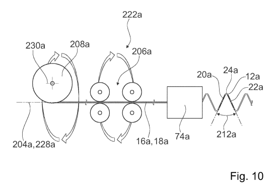
Fig. 10 shows a manufacturing device 222a for manufacturing the wire netting
10a. The manufacturing device 222a is provided for manufacturing the wire
netting
10a. The manufacturing device 222a has a bending device 74a. The longitudinal
CA 03052089 2019-07-30
- 18 -
element 16a or, in the present case, its wire 18a is bent by means of the
bending
device, which supplies the wire 18a to a bending step, wherein the wire 18a
while
being supplied is rotated about its longitudinal axis 204a. Regarding a
description of
bending device 74a, reference is made to figures 11 to 13. If, instead of the
wire 18a,
a longitudinal element not configured as a single wire such as a strand and/or
a wire
bundle or similar is used, this is processed and/or fed and/or bent and/or
straightened in a way similar to wire 18a. In the following, however, the case
is
described, in which the longitudinal element 16a is configured as a wire 18a.
The manufacturing device 222a has a rotating orienting apparatus 206a. In the
io manufacturing of helix 12a, the wire 18a passes through the rotating
orienting
apparatus 206a. The orienting apparatus 206a is rotatably mounted about a
rotation
axis 228a. The rotation axis 228a is equivalent to the longitudinal axis 204a
of the
wire 18a.
The manufacturing device 222a has a co-rotated reel 208a. In the production of
the helix 12a, the wire 18a is unwound from the co-rotated reel 208a. The co-
rotated
reel 208a is rotatably mounted about the rotation axis 228a. For unwinding the
wire
18a from the co-rotated reel 208a, the co-rotated reel 208a is rotated about
an
unwinding axis 230a, which is perpendicular to the rotation axis 228a. When
the co-
rotated reel 208a rotates about the rotation axis 228a, the unwinding axis
230a
rotates about the rotation axis 228a.
The manufacturing device 222a has a drive unit, not shown, which is provided
for rotating the co-rotated reel 208a and the orienting apparatus 206a and
thus the
wire 18a about the axis of rotation 228a. In the case shown, the orienting
apparatus
206a and the reel 208a rotate about the same rotation axis 228a. It is of
course also
conceivable that the wire 18a between the co-rotated reel 208a and the
orienting
apparatus 206a is guided around at least one curve and the orienting apparatus
206a
is rotated about a different axis of rotation than the reel 208a. In this
case, the
longitudinal axis 204a of the wire 18a extends in a region of the reel 208a
other than
in an area of the orienting apparatus 206a.
A twisting of the wire 18a during bending by the bending device 74a is
compensated by adjusting a rotational speed of the wire 18a.
The wire 18a is rotated for bending of the bending region 24a at least by a
compensation angle that is equivalent to an angle 212a between the first leg
22a and
CA 03052089 2019-07-30
- 19 -
the second leg 22a in a front view perpendicular to a main extension plane of
the
helix 12a. In particular, the first gradient angle 26a and half of the angle
212a
between the first leg 20a and the second leg 22a add up to 900. Upon bending
of the
wire 18a by means of the bending device 74a, a twist of the wire 18a is
generated for
each bent bending region by the angle 212a between the first leg 20a and the
second leg 22a. This generated torsion is compensated by the rotation of the
wire
18a about its longitudinal axis 204a. The wire 18a is thereby rotated in a
direction
which is equivalent to a direction of rotation of the helix 12a.
Fig. 11 shows the bending device 74a of the manufacturing device 222a in a
perspective view. Fig. 12 shows a bending space 140a of the bending device 74a
in
a first operating state in a perspective view. Fig. 13 shows the bending space
140a in
a second operating state in a perspective view. The bending device 74a is
adapted to
create the first helix 12a. The bending device 74a is adapted for bending the
first
helix 12a according to the geometry of the first helix 12a, in particular the
legs 20a,
22a and the bending region 24a of the first helix 12a. The bending device 74a
is
adapted to create the first helix 12a from the wire 18a. The wire 18a, in an
unbent
state, forms a helix blank 76a. The bending device 74a is provided for
manufacturing
the first helix 12a by means of bending the helix blank 76a.
The bending device 74a has a bending unit 78a. The bending unit 78 includes a
bending mandrel 80a and a bending table 82a. The bending table 82a is provided
for
bending the helix blank 76a around the bending mandrel 80a. The bending table
82a
is supported in order to circulate around the bending mandrel 80a. During
manufacturing, the bending table 82a continuously runs in a circulating
direction
142a around the bending mandrel 80a. The bending mandrel 80a has a
longitudinal
axis 144a. The longitudinal axis 144a of the bending mandrel 80a is parallel
to a
main extension direction 94a of the bending mandrel 80a.
The bending device 74a has a feeding unit 84a which is provided for advancing
the helix blank 76a along a feeding axis 86a in a feeding direction 88a. The
feeding
axis 86a is arranged parallel to the feeding direction 88a. The feeding
direction 88a
.. runs parallel to a main extension direction of the helix blank 76a. The
feeding axis
86a encloses an angle with the longitudinal axis 144a of the bending mandrel
80a
which is at least substantially and in particular exactly equivalent to the
first gradient
angle 26a. The first gradient angle 26a can be adjusted by adjusting the
feeding axis
CA 03052089 2019-07-30
- 20 -
86a relative to the longitudinal axis 144a of the mandrel 80a.
During manufacture, the helix blank 76a is repeatedly fed. The bending unit
78a, in particular the bending table 82a, bends after the feeding has been
completed,
the helix blank 76a respectively around the bending mandrel 80a in order to
produce
a bending region of the manufactured first helix 12a. The feeding unit 84a
releases
the helix blank 76a during bending so that it can rotate about the
longitudinal axis
204a of the wire 18a due to the rotation of the wire 18a. It is conceivable
that the wire
18a is guided around at least one curve and its longitudinal axis 204a in a
region of
the feeding unit 84a and/or in a region of the bending space 140a is different
from the
io axis of rotation 228a of co-rotated reel 208a and/or of the orienting
apparatus 206a.
A diameter of the bending mandrel 80a defines a bending curvature of the
bending
region 24a. In particular, the diameter of the bending mandrel 80a defines an
inner
radius of the bending region 24a.
The bending device 74a has an abutment unit 96a with at least one abutment
element 98a defining a maximum feeding position for the helix blank 76a. When
feeding, the helix blank 76a can be advanced by the feeding unit 84a up to the
maximum feeding position. The helix blank 76a, before bending by the bending
table
82a about the bending mandrel 80a, is in the maximum feeding position. In the
maximum feeding position, the helix blank 76a abuts the abutment element 98a
with
the last bent bending region 166a of the first helix 12a. The first operating
state
shown in Fig. 12 corresponds to a situation immediately before bending the
helix
blank 76a about the bending mandrel 80a. The helix blank 76a is in the first
operating
state in the maximum feeding position. The second operating state shown in
Fig. 13
corresponds to a situation during the bending of the helix blanks 76a about
the
bending mandrel 80a. The bending table 82a is displaced in the second
operating
state along the direction of rotation 142a with respect to its position in the
first
operating state.
The abutment element 98a is mounted completely circumferentially around the
bending mandrel 80a. The abutment element 98a runs, during manufacturing,
continuously about the bending mandrel 80a in the direction of circulation
142a.
The bending table 82a is pivotally mounted about a bending axis 102a, which
circulates around the bending mandrel 80a itself, in particular in the
direction of
circulation 142a, while the bending table 82a is rotated about the bending
mandrel
CA 03052089 2019-07-30
- 1 -
80a. The pivot axis 102a moves during manufacture on a circular path. The
pivot axis
102a moves at a constant angular velocity during manufacture. During bending,
the
bending table 82a and the abutment element 98a run around the bending mandrel
80a at the same speed. After bending, the bending table 82a pivots about the
pivot
axis 102a, thereby defining a maximum bending angle. The bending table 82a
then
pivots back around the pivot axis 102a, in particular during the advancement
of the
helix blank 76a. In the first operating state, the abutment element 98a rests
on the
bending table 82a.
In the present case, the bending mandrel 80a is driven. The bending mandrel
80a is rotatably mounted about its longitudinal axis 144a. The bending mandrel
80a
is coupled via a belt 164a to a drive unit, not shown, which in particular
further drives
the bending table 82a. The bending mandrel 80a is replaceable. The bending
unit
78a may be equipped with bending mandrels of different diameters.
A position of the bending table 82a relative to the abutment element 98a is
variable during the rotation of the bending table 82a around the bending
mandrel
80a.
The abutment element 98a has a concavely curved abutment surface 100a.
The abutment surface 100a is curved in the circumferential direction 142a with
a
circular arc shape. Further, the abutment surface 100a is curved in a circular
arc
perpendicular to the curvature in the circumferential direction 142a. A radius
of this
curvature perpendicular to the direction of rotation 142a at least
substantially
corresponds to a curvature of the bending region 24a. In the maximum feeding
position, the last bent bending region 166a bears against the abutment surface
100a,
which is circularly curved as an arc about the last bent bending region 166a.
In a feeding operating condition, in which the feeding of the helix blank 76a
takes place, the position of the abutment element 98a with respect to the
feeding axis
86 is variable. The abutment element 98a thus moves in the feeding state, in
particular after the helix blank 76a abuts against the abutment element 98a,
i.e. is in
the maximum feeding position, along the last bent bending region 166a, in the
direction of circulation 142a.
The bending unit 78a is adapted for bending a helix blank with at least one
high-
strength steel wire. In the present case, the helix blank 76a can be bent by
means of
the bending unit 78a.
CA 03052089 2019-07-30
- 22 -
The bending unit 78a is adapted for bending the helix blank 76a by more than
180 in a single revolution, in particular during each revolution of the
bending table
82a around the bending mandrel 80a. A bending angle is defined by a time of
pivoting of the bending table 82a about the pivot axis 102a. The bending unit
78a is
adapted to over-bend the helix blank 76a, in particular to compensate for
spring-back
of the helix blank 76a after bending due to its high bending stiffness. The
bending
unit 78a is adapted to provide the bending region 24a with a total angle of
exactly
180 , so that the first helix 12a can be made straight in itself.
In Figures 14 and 15 a further embodiment of the invention is shown. The
io .. following descriptions and the drawings are essentially limited to the
differences
between the exemplary embodiments, wherein, with regard to identically named
components, in particular with regard to components having the same reference
numerals, reference can in principle be made also to the drawings and/or the
description of the other embodiment, in particular of Figures 1 to 13. In
order to
distinguish the embodiments, the letter a has been added as a suffix to
reference
numerals of the embodiment in figures 1 to 13. In the embodiment of Figures 14
and
15, the letter a is replaced by the letter b.
Fig. 14 shows a part of a wire netting 10b having a plurality of helices 12b
braided with each other, at least one helix 12b of which is bent from at least
one
longitudinal element 16b and at least one first leg 20b, a second leg 22b and
comprises at least one first leg 20b, a second leg 22b as well as at least one
bending
region 24b interconnecting the first leg 20b and the second leg 22b. The
longitudinal
element 16b is bent at least essentially without torsion along a path of the
first leg
20b and the second leg 22b. In particular, a twisted state of the longitudinal
member
.. 16b in the wire netting 12b corresponds to a twisted state of a blank of
the
longitudinal member 16b before it being processed into the wire netting 12b.
In the
present case, the longitudinal member 16b is formed as a wire strand. The
longitudinal element 16b has at least one wire 18b made of high-strength
steel. In the
present case, the longitudinal element 16b is composed of a plurality of
identical
wires 18b, which are not shown individually in the figures. In a front view
perpendicular to a main extension plane of the helix 12b, the first leg 20b
extends at
a first gradient angle 26b with respect to the longitudinal direction 28b of
the helix
12b. In the present case, the first gradient angle 26b is about 450. The wire
netting
CA 03052089 2019-07-30
- 23 -
10b of the present case has square meshes.
Fig. 15 shows a portion of the wire netting 10b in a longitudinal view along a
longitudinal direction 28b of the helix 12b (see Figure 14). The first leg 20b
and the
second leg 22b have a curved contour. The wire netting 10b has bulgy meshes,
whereby in particular an impact of objects transversally to the wire netting
10b can be
damped.
The helix 12b is manufactured by means of a conventional braiding machine
with a braiding knife, which is not shown. The longitudinal member 16b is
rotated in
the manufacture of the helix 12b about its longitudinal axis to compensate for
a
torsion occurring during the bending of the longitudinal member 16b by the
braiding
knife.
CA 03052089 2019-07-30
- 24 -
Reference numerals
wire netting
5 12 helix
14 helix
16 longitudinal element
18 wire
leg
10 22 leg
24 bending region
26 gradient angle
28 longitudinal direction
gradient angle
15 32 bending region
54 front direction
74 bending device
76 helix blank
78 bending unit
20 80 bending mandrel
82 bending table
84 feeding unit
86 feeding axis
88 feeding direction
25 94 main extension direction
96 abutment unit
98 abutment element
100 abutment surface
102 rotation axis
30 109 longitudinal axis
110 longitudinal axis
112 main extension direction
114 longitudinal axis
CA 03052089 2019-07-30
- 25 -
118 intersection angle
140 bending space
142 circulation direction
144 longitudinal axis
164 belt
166 bending region
200 surface structure
202 preferential direction
203 preferential direction
204 longitudinal axis
206 orienting apparatus
208 reel
212 angle
214 surface structure element
216 surface structure element
218 surface structure element
220 main extension direction
222 manufacturing device
224 method step
226 method step
228 rotation axis
230 unwinding axis