Note: Descriptions are shown in the official language in which they were submitted.
CA 03052788 2019-08-06
WO 2018/145096
PCT/US2018/017078
ANATOMICAL GRIPPING SYSTEM FOR GRIPPING THE LEG AND
FOOT OF A PATIENT WHEN EFFECTING HIP DISTRACTION
AND/OR WHEN EFFECTING LEG POSITIONING
Applicant
Stryker Corp.
Inventors
William Kaiser
Ian Kovacevich
Jeremy Graul
John Parker
Nouphone Bansasine
James Flom
Reference To Pending Prior Patent Applications
This patent application claims benefit of:
(i) pending prior U.S. Provisional Patent
Application Serial No. 62/455,154, filed 02/06/2017 by
Stryker Corp. and William Kaiser et al. for ANATOMICAL
GRIPPING SYSTEM (Attorney's Docket No. FIAN-118 PROV);
and
(ii) pending prior U.S. Provisional Patent
Application Serial No. 62/546,629, filed 08/17/2017 by
Stryker Corp. and William Kaiser et al. for ANATOMICAL
GRIPPING SYSTEM FOR GRIPPING THE LEG OF A PATIENT WHEN
EFFECTING HIP DISTRACTION OR LEG POSITIONING
(Attorney's Docket No. FIAN-124 PROV).
CA 03052788 2019-08-06
WO 2018/145096
PCT/US2018/017078
- 2 -
The two (2) above-identified patent applications
are hereby incorporated herein by reference.
Field Of The Invention
This invention relates to medical apparatus in
general, and more particularly to medical apparatus
for gripping the leg and foot of a patient when
effecting hip distraction and/or when effecting leg
positioning.
Background Of The Invention
When performing surgical procedures on the hip
joint, it is common to distract the hip joint prior to
the surgery so as to provide additional room within
the joint and so as to better present selected anatomy
to the surgeon. This hip distraction is commonly
achieved by applying a distraction force to the distal
end of the leg of the patient. The distraction force
applied to the distal end of the leg of the patient is
typically around 50-100 pounds (or more) of force.
Currently, a surgical boot is placed on the foot and
lower leg of the patient, the surgical boot is
connected to a distraction frame, and then the
distraction frame is used to apply a distraction force
to the boot, whereby to apply a distraction force to
the leg of the patient. Securing the leg of the
patient to the distraction frame also allows for
appropriate positioning of the leg of the patient
CA 03052788 2019-08-06
WO 2018/145096
PCT/US2018/017078
- 3 -
during various surgical procedures (e.g., such as when
placing the leg into abduction).
Unfortunately, in many cases, the foot and lower
leg of the patient (and particularly the heel of the
patient) can slip within the surgical boot when the
distraction force is applied, thereby reducing the
amount of distraction achieved. This is particularly
true with patients who have small feet and wide
ankles, since this makes it difficult to secure the
patient's anatomy within the surgical boot. Such
slippage of the anatomy within the surgical boot can
be highly problematic, since the amount of hip
distraction achieved is typically fairly small to
begin with, and hence any slippage of the anatomy
within the surgical boot can further reduce the amount
of hip distraction achieved. In addition, when the
anatomy of the patient slips within the surgical boot,
the points of engagement between the surgical boot and
the anatomy shift, such that the anatomy may be out of
position within the surgical boot and/or the anatomy
may no longer be properly oriented relative to the
distraction frame. For this reason, many surgeons
personally strap the patient's foot and lower leg into
the surgical boot in an effort to ensure that the foot
and lower leg of the patient are secured to the
maximum extent possible within the surgical boot. It
is also common for surgeons to augment the fit of the
surgical boot with extra tape, bandages and/or padding
CA 03052788 2019-08-06
WO 2018/145096
PCT/US2018/017078
- 4 -
in order to minimize slippage within the surgical
boot.
Summary Of The Invention
The present invention provides a new and improved
approach for securing the leg of a patient to a
distraction frame, wherein the conventional surgical
boot is replaced by a novel anatomical gripping system
which eliminates the problems associated with
conventional surgical boots.
In one form of the invention, there is provided
an anatomical gripping system comprising:
a binding comprising:
a substantially rigid spine;
a calf shell mounted to the substantially
rigid spine;
an anterior shell; and
a clamping mechanism connecting the anterior
shell to the calf shell;
wherein the calf shell comprises a flexible
portion configured to selectively engage the superior
portion of the calcaneus bone of a patient;
and further wherein when the clamping mechanism
applies a force to the flexible portion of the calf
shell, the flexible portion of the calf shell is drawn
into engagement with the superior portion of the
calcaneus bone of the patient.
CA 03052788 2019-08-06
WO 2018/145096
PCT/US2018/017078
- 5 -
In another form of the invention, there is
provided a method for distracting a hip joint, the
method comprising:
providing an anatomical gripping system
comprising:
a binding comprising:
a substantially rigid spine;
a calf shell mounted to the
substantially rigid spine;
an anterior shell; and
a clamping mechanism connecting the
anterior shell to the calf shell;
wherein the calf shell comprises a
flexible portion configured to selectively engage the
superior portion of the calcaneus bone of a patient;
and further wherein when the clamping
mechanism applies a force to the flexible portion of
the calf shell, the flexible portion of the calf shell
is drawn into engagement with the superior portion of
the calcaneus bone of the patient;
positioning the patient's foot and lower leg in
the binding;
using the clamping mechanism to apply a force to
the flexible portion of the calf shell so that the
flexible portion of the calf shell is drawn into
engagement with the superior portion of the calcaneus
bone of the patient; and
CA 03052788 2019-08-06
WO 2018/145096
PCT/US2018/017078
- 6 -
applying a distracting force to the substantially
rigid spine of the binding.
In another form of the invention, there is
provided an anatomical gripping system comprising:
a soft wrap for covering at least a portion of a
patient's lower leg superior to the malleoli bones
while not covering the bony prominence of the malleoli
bones; and
a binding comprising:
a substantially rigid spine;
a calf shell mounted to the substantially
rigid spine;
an anterior shell; and
a clamping mechanism connecting the anterior
shell to the calf shell;
such that when the clamping mechanism applies a
clamping force between the anterior shell and the calf
shell, the clamping force is directed onto the soft
wrap covering at least a portion of the patient's
lower leg superior to the malleoli bones.
In another form of the invention, there is
provided a method for distracting a hip joint, the
method comprising:
providing an anatomical gripping system
comprising:
a soft wrap for covering at least a portion
of a patient's lower leg above the malleoli bones
CA 03052788 2019-08-06
WO 2018/145096
PCT/US2018/017078
- 7 -
while not covering the bony prominence of the malleoli
bones; and
a binding comprising:
a substantially rigid spine;
a calf shell mounted to the
substantially rigid spine;
an anterior shell; and
a clamping mechanism connecting the
anterior shell to the calf shell;
such that when the clamping mechanism
applies a clamping force between the anterior shell
and the calf shell, the clamping force is directed
onto the soft wrap covering at least a portion of the
patient's lower leg above the malleoli bones;
positioning the patient's foot and lower leg in
the binding;
using the clamping mechanism to apply a clamping
force between the anterior shell and the calf shell,
such that the clamping force is directed onto the soft
wrap covering at least a portion of the patient's
lower leg above the malleoli bones; and
applying a distracting force to the substantially
rigid spine of the binding.
In another form of the invention, there is
provided an anatomical gripping system comprising:
a binding comprising:
a substantially rigid spine;
CA 03052788 2019-08-06
WO 2018/145096
PCT/US2018/017078
- 8 -
a calf shell mounted to the substantially
rigid spine;
an anterior shell; and
at least two clamping mechanisms connecting
the anterior shell to the calf shell;
wherein the at least two clamping mechanisms
apply clamping forces between the anterior shell and
the calf shell;
and further wherein the anterior shell comprises
reduced width between the at least two clamping
mechanisms so as to provide the anterior shell with
increased flexibility for conforming to the anatomy of
a patient.
In another form of the invention, there is
provided a method for distracting a hip joint, the
method comprising:
providing an anatomical gripping system
comprising:
a binding comprising:
a substantially rigid spine;
a calf shell mounted to the
substantially rigid spine;
an anterior shell; and
at least two clamping mechanisms
connecting the anterior shell to the calf shell;
wherein the at least two clamping
mechanisms apply clamping forces between the anterior
shell and the calf shell;
CA 03052788 2019-08-06
WO 2018/145096
PCT/US2018/017078
- 9 -
and further wherein the anterior shell
comprises reduced width between the at least two
clamping mechanisms so as to provide the anterior
shell with increased flexibility for conforming to the
anatomy of a patient;
positioning the patient's foot and lower leg in
the binding;
using the at least two clamping mechanisms to
apply a clamping force between the anterior shell and
the calf shell, such that the clamping force is
directed onto the anatomy of a patient; and
applying a distracting force to the substantially
rigid spine of the binding.
Brief Description Of The Drawings
These and other objects and features of the
present invention will be more fully disclosed or
rendered obvious by the following detailed description
of the preferred embodiments of the invention, which
is to be considered together with the accompanying
drawings wherein like numbers refer to like parts, and
further wherein:
Fig. 1 is a schematic view showing a surgical
table, a distraction frame, and portions of a novel
anatomical gripping system formed in accordance with
the present invention;
CA 03052788 2019-08-06
WO 2018/145096
PCT/US2018/017078
- 10 -
Figs. 2-4 are schematic views showing a novel
anatomical gripping system formed in accordance with
the present invention;
Figs. 5 and 6 are schematic views showing some of
the bones of the foot and lower leg of a human;
Figs. 7, 7A, 8 and 9 are schematic views showing
further details of the soft butterfly wrap of the
novel anatomical gripping system of the present
invention;
Figs. 9A-9D are schematic views showing another
soft butterfly wrap of the novel anatomical gripping
system of the present invention;
Fig. 10 is a schematic view showing how the novel
anatomical gripping system of the present invention
applies forces to the foot and lower leg of a patient;
Figs. 11, 12, 12A, 12B and 13 are schematic views
showing further details of the soft liner of the novel
anatomical gripping system of the present invention;
Fig. 13A is a schematic view showing further
details of the soft butterfly wrap and the novel soft
liner of the anatomical gripping system of the present
invention; and
Figs. 14-34 are schematic views showing further
details of the binding of the novel anatomical
gripping system of the present invention.
Detailed Description Of The Preferred Embodiments
CA 03052788 2019-08-06
WO 2018/145096
PCT/US2018/017078
- 11 -
The present invention provides a new and improved
approach for securing the leg of a patient to a
distraction frame, wherein the conventional surgical
boot is replaced by a novel anatomical gripping system
which eliminates the problems associated with
conventional surgical boots.
More particularly, and looking first at Fig. 1,
the present invention comprises a novel anatomical
gripping system 5 formed in accordance with the
present invention. Anatomical gripping system 5 is
intended to grip the foot and lower leg of a patient
lying on a surgical table 10, with anatomical gripping
system 5 being connected to a distraction frame 15,
such that distraction frame 15 can apply a distraction
force to the leg of a patient via anatomical gripping
system 5.
Anatomical Gripping System 5 In General
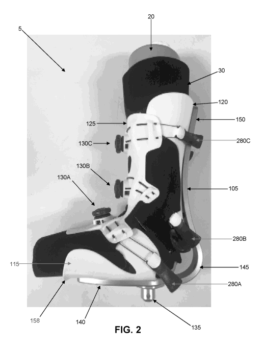
Anatomical gripping system 5 is shown gripping a
simulation leg 20 in Figs. 2-4. As will hereinafter
be discussed, anatomical gripping system 5 comprises
various components which are designed to optimize the
manner in which anatomical gripping system 5 grips the
foot and lower leg of a patient. Significantly, this
results in enhanced gripping of the anatomy by
anatomical gripping system 5, and less slippage of the
anatomy relative to anatomical gripping system 5,
CA 03052788 2019-08-06
WO 2018/145096
PCT/US2018/017078
- 12 -
particularly with respect to slippage of the heel of
the patient relative to anatomical gripping system 5.
More particularly, Figs. 5 and 6 show some of the
bones of the foot and lower leg of a human. In
accordance with the present invention, and as will
hereinafter be discussed in further detail, anatomical
gripping system 5 is designed to grip the foot of the
patient at the forefoot and at the calcaneus bone,
i.e., on the superior (i.e., proximal) surface of the
calcaneus bone (Figs. 5 and 10), and to grip the leg
of the patient superior at the malleoli, i.e., on the
superior (i.e., proximal) surface of the lateral
malleolus of the fibula and on the superior (i.e.,
proximal) surface of the medial malleolus of the tibia
(Figs. 6 and 10) (as used herein, the terms "superior
to" and "proximal to" are intended to be understood as
being in the cephalad direction on a patient, and
"inferior to" and "distal to" are intended to be
understood as being in the caudal direction on a
patient).
Significantly, and as will hereinafter be
discussed, anatomical gripping system 5 is designed to
securely grip the essential anatomy of the patient
without requiring adjacent non-essential anatomy to be
tightly squeezed, thus reducing the pressure that the
remaining surfaces of the foot and lower leg receive.
Gripping the foot and lower leg of the patient using
the prominent bones of the foot and lower leg of the
CA 03052788 2019-08-06
WO 2018/145096
PCT/US2018/017078
- 13 -
patient (i.e., the calcaneus and malleoli bones)
ensures a secure grip of the foot and lower leg of the
patient while minimizing trauma to the anatomy of the
patient. This approach is in sharp contrast to the
approach of conventional surgical boots, which seek to
tighten down the surgical boot across the dorsum of
the foot and about the ankle of the patient, in a
relatively focal zone which contains soft tissue,
nerves and blood supply. The use of conventional
surgical boots can lead to injury if the surgical boot
is excessively tightened, but can also lead to
slippage if the surgical boot is not sufficiently
tightened.
Additionally, conventional surgical boots
generally hold the foot of a patient at a 90 degree
angle relative to the lower leg of the patient. While
this disposition of the foot relative to the lower leg
of the patient may be appropriate for footwear of the
sort used for walking, it is not necessarily optimal
for gripping the foot and lower leg of the patient for
hip distraction purposes. By contrast, and as will
hereinafter be discussed, the present invention may be
configured to hold the foot of the patient at an angle
of approximately 100 degrees relative to the lower leg
of the patient. Inclining the foot of the patient at
an angle of approximately 100 degrees relative to the
lower leg of the patient places the calcaneus bone in
a more pronounced position and thus allows for
CA 03052788 2019-08-06
WO 2018/145096
PCT/US2018/017078
- 14 -
significantly improved gripping of the foot and lower
leg of the patient by anatomical gripping system 5.
The aforementioned approximately 100 degree incline
between the foot of the patient and the lower leg of
the patient may also provide the additional benefit of
greater comfort for the patient. Note that, if
desired, the angle of incline between the foot and
lower leg of the patient may also be greater than
approximately 100 degrees in order to allow for more
flex of the foot. Note also that, if desired, the
angle of incline between the foot and lower leg of the
patient may be less than approximately 100 degrees,
but preferably is not less than approximately 90
degrees.
In accordance with the present invention,
anatomical gripping system 5 generally comprises three
components:
(i) a soft butterfly wrap 25 (Figs. 7, 7A and 8-
11);
(ii) a soft liner 30 (Figs. 2-4, 10-12, 12A, 12B,
13 and 13A); and
(iii) a binding 35 (Figs. 2-4, 10 and 14-34).
A. Soft Butterfly Wrap 25
Soft butterfly wrap 25 (Figs. 7, 7A and 8-11) is
intended to be positioned directly against the skin of
the patient on both sides of the malleoli. Soft
butterfly wrap 25 is preferably formed out of a foam
CA 03052788 2019-08-06
WO 2018/145096
PCT/US2018/017078
- 15 -
of density and stiffness similar to what may be seen
in performance sports footwear like ski boots, snow
board boots and skates. The foam serves to "build up"
the anatomy of the patient distal (i.e., inferior) to
the malleoli and proximal (i.e., superior) to the
malleoli, whereby to facilitate gripping the anatomy
of the patient both distal (i.e., inferior) and
proximal (i.e., superior) to the malleoli, and whereby
to facilitate distributing the gripping load imposed
on the anatomy of the patient.
More particularly, soft butterfly wrap 25
comprises a lower band 40, an upper band 45 and a
connecting portion 50. Lower band 40 surrounds the
mid-foot and forefoot of the patient. Upper band 45
surrounds the lower leg proximal (i.e., superior) to
the malleoli. Connecting portion 50 connects lower
band 40 of soft butterfly wrap 25 with upper band 45
of soft butterfly wrap 25. Note that a gap 55 is
formed between lower band 40 and upper band 45, with
gap 55 including the region over the malleoli. Note
also that an opening 60 is formed distal (i.e.,
inferior) to connecting portion 50 in the region of
the heel of the patient. Thus, soft butterfly wrap 25
does not cover the heel of the patient or otherwise
engage the heel of the patient. This is to allow the
surgical staff to visualize or measure the spacing of
the heel of the patient from binding 35 (see below).
CA 03052788 2019-08-06
WO 2018/145096
PCT/US2018/017078
- 16 -
In one form of the invention, lower band 40 is
formed by two straps 65, 70 which are adjustably
connectable to one another (e.g., via hook-and-loop
fasteners) so as to form the complete lower band 40,
and upper band 45 is formed by two straps 75, 80 which
are adjustably connectable to one another (e.g., via
hook-and-loop fasteners) so as to form the complete
upper band 45. Alternatively, one or both of lower
band 40 and upper band 45 may comprise a sleeve which
encircles the foot (lower band 40) or leg (upper band
45) for disposition about the anatomy of the patient,
wherein the sleeve comprises an elastic material so as
to allow the sleeve to closely conform to the anatomy
of the patient.
If desired, the interior surfaces of soft
butterfly wrap 25 may at least partially comprise a
high friction material (e.g., silicone rubber). The
inclusion of this high friction material increases the
gripping action between soft butterfly wrap 25 and the
foot and lower leg of the patient.
Figs. 9A-9D show another soft butterfly wrap 25
also formed in accordance with the present invention.
B. Soft Liner 30
Soft liner 30 (Figs. 2-4, 10-12, 12A, 12B, 13 and
13A) is intended to be draped over the foot and calf
of the patient (and over soft butterfly wrap 25) so as
to provide protective and hygienic coverage for the
CA 03052788 2019-08-06
WO 2018/145096
PCT/US2018/017078
- 17 -
distal end of the patient's leg. Soft liner 30
preferably comprises an opening 82 (see Fig. 13) in
the region of the heel of the patient so that soft
liner 30 does not cover the heel of the patient or
otherwise engage the heel of the patient. This is to
allow the surgical staff to visually examine the
position of the patient's heel within binding 35,
particularly during leg distraction, and particularly
for the purpose of checking for undesired heel lift
during leg distraction (or other leg positioning).
Additionally, soft liner 30 does not cover the toes of
the patient (see, for example, Fig. 12). This is so
that the surgical staff can examine the toes of the
patient during the surgical procedure (e.g., so as to
ensure that the toes of the patient have adequate
blood circulation).
In one form of the invention, soft liner 30 is
formed by four segments 85, 90, 95, 100, with segments
85, 90 being adjustably connectable to one another
(e.g., via hook-and-loop fasteners) so as to cover a
portion of the foot of the patient (and so as to cover
lower band 40 of soft butterfly wrap 25), and with
segments 95, 100 being adjustably connectable to one
another (e.g., via hook-and-loop fasteners) so as to
cover a portion of the leg of the patient (and so as
to cover upper band 45 of soft butterfly wrap 25). In
one form of the invention, and looking now at Figs.
12A and 12B, soft liner 30 may comprise two panels
CA 03052788 2019-08-06
WO 2018/145096
PCT/US2018/017078
- 18 -
101, 102, where panel 101 comprises the aforementioned
segments 85 and 90, and where panel 102 comprises the
aforementioned segments 95 and 100, with panels 101,
102 being sewn together at sew tabs 103.
Alternatively, soft liner 30 may comprise a
sleeve for disposition around the anatomy of the
patient, wherein the sleeve comprises an elastic
material so as to allow the sleeve to closely conform
to the anatomy of the patient.
If desired, the interior surfaces of soft liner
30 may at least partially comprise a high friction
material (e.g., silicone rubber). The inclusion of
this high friction material increases the gripping
action between soft liner 30 and soft butterfly wrap
25, and increases the gripping action between soft
liner 30 and the foot and lower leg of the patient.
In addition, if desired, the exterior surfaces of
soft liner 30 may at least partially comprise a high
friction material (e.g., silicone rubber). The
inclusion of this high friction material increases the
gripping action between soft liner 30 and binding 35.
If desired, soft butterfly wrap 25 and soft liner
may be formed as two separate components, and they
may be applied to the patient in two distinct steps,
25 i.e., first soft butterfly wrap 25 is applied to the
patient, and then soft liner 30 is applied to the
patient (and over soft butterfly wrap 25). More
preferably, however, and looking now at Fig. 13A, soft
CA 03052788 2019-08-06
WO 2018/145096
PCT/US2018/017078
- 19 -
butterfly wrap 25 and soft liner 30 are provided as a
singular construction (e.g., soft butterfly wrap 25 is
secured to soft liner 30 at the time of manufacture).
This singular construction may be effected by simply
attaching soft butterfly wrap 25 to soft liner 30, or
by incorporating the features of both components
(i.e., soft butterfly wrap 25 and soft liner 30) in a
single modified construction.
C. Binding 35
Binding 35 (Figs. 2-4, 10 and 14-34) is intended
to be positioned over soft butterfly wrap 25 and soft
liner 30 after soft butterfly wrap 25 and soft liner
30 have been positioned on the foot and lower leg of
the patient, and then binding 35 is intended to be
secured to the foot and lower leg of the patient, such
that binding 35 can thereafter be used to secure the
leg of the patient to distraction frame 15.
Binding 35 generally comprises a long, narrow
spine 105, a plantar shell 115, a calf shell 120, an
anterior shell 125 and three cable assemblies 130A,
130B and 130C.
(i) Long, Narrow Spine 105
Long, narrow spine 105 (Figs. 2, 3, 10 and 19-24)
extends from approximately the arch of the foot of the
patient to the calf of the patient, and includes a
CA 03052788 2019-08-06
WO 2018/145096
PCT/US2018/017078
- 20 -
mount 135 (Fig. 2) for mounting long, narrow spine 105
to distraction frame 15.
More particularly, long, narrow spine 105
comprises a plantar portion 140, a curved portion 145
and a calf portion 150. Plantar portion 140 is
preferably set at an angle of approximately 100
degrees relative to calf portion 150 so as to place
the calcaneus bone in a more pronounced position when
the foot and lower leg of the patient are gripped by
anatomical gripping system 5, whereby to provide
improved gripping of the anatomy of the patient, and
so as to provide increased comfort for the patient.
Curved portion 145 curves away from the heel of the
patient (see Figs. 2 and 3) so as to allow the
surgical staff to visualize or measure the spacing of
the heel of the patient from long, narrow spine 105.
(ii) Plantar Shell 115
Plantar shell 115 (Figs. 2-4, 10, 14-21, 23 and
24) is attached to plantar portion 140 of long, narrow
spine 105. More particularly, plantar shell 115
comprises a base 153 which terminates short of the
toes of the patient and which terminates short of the
heel of the patient (Figs. 2, 3 and 21). Plantar
shell 115 further comprises flanges 155 and 156 (Fig.
15) which are separated by openings or cutouts 157.
Flanges 155 and 156 serve to prevent the foot of the
patient from rolling or pivoting relative to plantar
CA 03052788 2019-08-06
WO 2018/145096
PCT/US2018/017078
- 21 -
shell 115 (and hence from rolling or pivoting relative
to binding 35). Openings 157 between flanges 155 and
156 enable flanges 156 to flex when tension is applied
to flanges 156 by cable assembly 130A (see below) so
that flanges 156 closely conform to the foot of the
patient, thereby improving the grip of binding 35 on
the foot of the patient. Base 153 of plantar shell
115 preferably also comprises an outward relief 158
for reducing the pressure of the distal lower edge of
base 153 of plantar shell 115 against the bottom of
the foot of the patient (i.e., so that there is not a
sharp edge that may cause iatrogenic damage to the
foot of the patient).
In one preferred form of the invention, plantar
shell 115 is formed out of a flexible plastic material
(e.g., Nylon) which is sufficiently ductile to enable
the plantar shell to conform to the anatomy of a
patient while still being sufficiently firm to provide
support to the anatomy of a patient.
Plantar shell 115 also comprises plantar cable
mounts 160. Plantar cable mounts 160 are preferably
formed on the aforementioned flanges 156. Plantar
cable mounts 160 are intended to be aligned with lower
band 40 of soft butterfly wrap 25, and to receive
portions of cable assembly 130A, so that a gripping
force can be applied about lower band 40 of soft
butterfly wrap 25 when cable assembly 130A is
tightened, as will hereinafter be discussed. In one
CA 03052788 2019-08-06
WO 2018/145096
PCT/US2018/017078
- 22 -
preferred form of the invention, plantar cable mounts
160 may comprise "quick release" cable mounts of the
sort adapted to receive and support portions of cable
assembly 130A, as will hereinafter be discussed.
(iii) Calf Shell 120
Calf shell 120 (Figs. 2, 3, 10 and 14-24) is
attached to calf portion 150 of long, narrow spine
105. More particularly, calf shell 120 comprises a
top portion 165 and a bottom portion 170.
Significantly, and as will hereinafter be discussed in
further detail, bottom portion 170 of calf shell 120
can flex relative to the remainder of calf shell 120
and terminates short of the heel of the patient.
Top portion 165 of calf shell 120 comprises
flanges 175 (Fig. 19) which serve to prevent the
anatomy of a patient from rolling or pivoting relative
to calf shell 120 (and hence from rolling or pivoting
relative to binding 35).
Bottom portion 170 of calf shell 120 projects
toward the Achilles tendon of the patient, but stops
short of the heel of the patient, as will hereinafter
be discussed. Bottom portion 170 of calf shell 120
comprises flanges 180 which serve to prevent the
anatomy of a patient from rolling or pivoting relative
to calf shell 120 (and hence from rolling or pivoting
relative to binding 35).
CA 03052788 2019-08-06
WO 2018/145096
PCT/US2018/017078
- 23 -
In one preferred form of the invention, bottom
portion 170 of calf shell 120 further comprises a
collar 185 set at the bottom end of bottom portion
170. Note that collar 185 also covers a portion of
flanges 180. Collar 185 closely engages the anatomy
of the patient in the region of the Achilles tendon.
See Figs 17-19. More particularly, collar 185 is
secured to bottom portion 170 of calf shell 120 and
"nestles" around the anatomy of the patient just above
the calcaneus, covering the Achilles tendon of the
patient, whereby to closely engage the anatomy of the
patient. In one form of the invention, collar 185
comprises a rubber member which covers and supports
the anatomy of the patient, but is soft and compliant
for comfort.
Note that flanges 175 (at the top portion 165 of
calf shell 120) and flanges 180 (at the bottom portion
170 of calf shell 120) are separated from one another
by openings or cutouts 187. Openings 187 between
flanges 175 and flanges 180 enable flanges 175 to flex
when tension is applied to flanges 175 by cable
assembly 130C (see below) so that flanges 175 closely
conform to the calf of the patient, thereby improving
the grip of binding 35 on the leg of the patient; and
openings 187 between flanges 175 and flanges 180
enable flanges 180 to flex when tension is applied to
flanges 180 by cable assembly 130B (see below) so that
flanges 180 closely conform to the region of the
CA 03052788 2019-08-06
WO 2018/145096
PCT/US2018/017078
- 24 -
patient just proximal (i.e., superior) to the
calcaneus, thereby improving the grip of binding 35 on
the leg of the patient.
In one preferred form of the invention, calf
shell 120 is formed out of a flexible plastic material
(e.g., Nylon) which is sufficiently ductile to enable
the calf shell to conform to the anatomy of a patient
while still being sufficiently firm to provide support
to the anatomy of a patient.
Bottom portion 170 of calf shell 120 comprises
lower calf cable mounts 190, and top portion 165 of
calf shell 120 comprises upper calf cable mounts 195.
Top portion 165 of calf shell 120 is secured to calf
portion 150 of long, narrow spine 105, and bottom
portion 170 of calf shell 120 is free to flex in the
region of lower cable mounts 190, i.e., bottom portion
170 of calf shell 120 is not secured to long, narrow
spine 105, in order to allow bottom portion 170 of
calf shell 120 to "float" in a cantilever fashion.
Significantly, when tension is applied to flanges 180
by cable assembly 130B (see below), bottom portion 170
of calf shell 120 is flexed toward the anatomy of the
patient, thereby improving the grip of binding 35 on
the leg of the patient.
Lower cable mounts 190 are intended to be aligned
with upper band 45 of soft butterfly wrap 25, and to
receive portions of cable assembly 130B, so that a
gripping force can be applied about upper band 45 of
CA 03052788 2019-08-06
WO 2018/145096
PCT/US2018/017078
- 25 -
soft butterfly wrap 25 when cable assembly 130B is
tightened, as will hereinafter be discussed. Note
that inasmuch as bottom portion 170 of calf shell 120
is not secured to long, narrow spine 105 in order to
allow bottom portion 170 to "float" in a cantilever
fashion, bottom portion 170 of calf shell 120 is free
to flex anteriorly when tension is applied to cable
assembly 130B, whereby to enhance the engagement of
collar 185 with the anatomy of the patient.
Upper calf cable mounts 195 are intended to be
aligned with the lower- to mid-calf region of the
patient, and to receive portions of cable assembly
130C, so that a gripping force can be applied about
the lower- to mid-calf region of the patient when
cable assembly 130C is tightened, as will hereinafter
be discussed.
In one preferred form of the invention, lower
calf cable mounts 190 comprise "quick release" cable
mounts of the sort adapted to receive and support
portions of cable assembly 130B, as will hereinafter
be discussed, and upper calf cable mounts 195 comprise
"quick release" cable mounts of the sort adapted to
receive and support portions of cable assembly 130C,
as will hereinafter be discussed.
Plantar shell 115 and calf shell 120 are spaced
apart from one another in the region of the heel of
the patient. In addition, curved portion 145 of long,
narrow spine 105 is spaced away from the heel of the
CA 03052788 2019-08-06
WO 2018/145096
PCT/US2018/017078
- 26 -
patient. Thus, binding 35 is open in the region of
the heel of the patient, and does not cover the heel
of the patient or otherwise engage the heel of the
patient. This construction allows the surgical staff
to visualize or measure the spacing of the heel of the
patient from long, narrow spine 105.
(iv) Anterior Shell 125
Anterior shell 125 (Figs. 2-4, 10, 14-16, 20, 21,
23 and 24) is connected to plantar shell 115 by cable
assembly 130A, and anterior shell 125 is connected to
calf shell 120 by cable assembly 130B and cable
assembly 130C. Tensioning of cable assemblies 130A,
130B and 130C causes anterior shell 125 of binding 35
to move towards plantar shell 115 and calf shell 120,
and tensioning of cable assembly 130B causes bottom
portion 170 of calf shell 120 to flex anteriorly
towards the Achilles tendon of the patient, so that
binding 35 securely grips the anatomy of the patient.
In one preferred form of the invention, anterior
shell 125 comprises a first section 200, a second
section 205 and a third section 210. First section
200 is connected to second section 205 by a pair of
webs 215, and second section 205 is connected to third
section 210 by a pair of webs 220.
Referring to Fig. 4, first section 200 of
anterior shell 125 comprises flanges 235 and cable
guides 240. First section 200, flanges 235 and cable
CA 03052788 2019-08-06
WO 2018/145096
PCT/US2018/017078
- 27 -
guides 240 are intended to be aligned with lower band
40 of soft butterfly wrap 25, and to receive portions
of cable assembly 130A, so that a gripping force can
be applied about lower band 40 of soft butterfly wrap
25 when cable assembly 130A is tightened, as will
hereinafter be discussed.
Second section 205 of anterior shell 125
comprises flanges 245 and cable guides 250. Second
section 205, flanges 245 and cable guides 250 are
intended to be aligned with upper band 45 of soft
butterfly wrap 25, and to receive portions of cable
assembly 130B, so that a gripping force can be applied
about upper band 45 of soft butterfly wrap 25 when
cable assembly 130B is tightened, as will hereinafter
be discussed.
Third section 210 of anterior shell 125 comprises
flanges 255 and cable guides 260. Third section 210,
flanges 255 and cable guides 260 are intended to be
aligned with the lower- to mid-calf region of the
patient, and to receive portions of cable assembly
130C, so that a gripping force can be applied about
the lower- to mid-calf region of the patient when
cable assembly 130C is tightened, as will hereinafter
be discussed.
Openings or cutouts 300 (Fig. 4) are provided
between flanges 235 and 245, and openings or cutouts
305 are provided between flanges 245 and 255, and an
opening or cutout 310 is provided between first
CA 03052788 2019-08-06
WO 2018/145096
PCT/US2018/017078
- 28 -
section 200 and second section 205, and an opening or
cutout 315 is provided between second section 205 and
third section 210, in order to provide flexibility to
anterior shell 125 which enables anterior shell 125 to
conform to the foot and lower leg of the patient as
cable assemblies 130A, 130B and 130C are tightened. A
flange 267, extending distally from first section 200
of anterior shell 125 (Fig. 4), distributes load onto
the dorsal portion of the foot to prevent pressure
points. An opening or cutout 320 provides flexibility
to flange 267 so that excess pressure is not applied
to the dorsal portion of the foot.
In one preferred form of the invention, anterior
shell 125 is formed out of a flexible plastic material
(e.g., Nylon) which is sufficiently ductile to enable
the anterior shell to conform to the anatomy of a
patient while still being sufficiently firm to provide
support to the anatomy of a patient.
If desired, and looking now at Fig. 24, anterior
shell 125 may comprise a rubber cushion 325 on the
inside surface of first section 200 of anterior shell
125, and a rubber cushion 330 on the inside surface of
second section 205 of anterior shell 125, and a rubber
cushion 335 on the inside surface of third section 210
of anterior shell 120. Rubber cushions 325, 330, 335
may comprise a rubber (or foam rubber) material of a
durometer which is softer than anterior shell 125 but
firmer than soft liner 30. Thus, in this
CA 03052788 2019-08-06
WO 2018/145096
PCT/US2018/017078
- 29 -
construction, soft liner 30, rubber cushions 325, 330,
335 and anterior shell 125 have increasing durometers,
which assists in distributing loads from anterior
shell 125 onto the foot of the patient, thereby
reducing high pressure locations on the foot.
(v) Cable Assemblies 130A, 130B And 130C
Cable assembly 130A connects anterior shell 125
to plantar shell 115, and cable assemblies 130B and
130C connect anterior shell 125 to calf shell 120.
Tensioning of cable assemblies 130A, 130B and 130C
causes anterior shell 125 of binding 35 to move
towards plantar shell 115 and calf shell 120 (Fig.
10), and tensioning of cable assembly 130B causes
bottom portion 170 of calf shell 120 to flex
anteriorly towards the Achilles tendon of the patient
(Fig. 10), so that binding 35 securely grips the
anatomy of the patient.
Cable assembly 130A comprises a cable 270A, a
rotary tightening mechanism 275A disposed intermediate
cable 270A for tensioning cable 270A, and a pair of
pull tabs 280A disposed at opposing ends of cable
270A. If desired, cable guards 285A may be mounted to
first section 200 of anterior shell 125 to guide cable
270A as it passes along first section 200 of anterior
shell 125. Rotary tightening mechanism 275A is
mounted to first section 200 of anterior shell 125,
cable 270A is passed through cable guides 240 (and
CA 03052788 2019-08-06
WO 2018/145096
PCT/US2018/017078
- 30 -
cable guards 285A if they are provided), and pull tabs
280A are used to facilitate mounting and dismounting
of cable 270A to plantar cable mounts 160.
On account of the foregoing construction, when
cable 270A is mounted on plantar cable mounts 160 and
rotary tightening mechanism 275A is thereafter turned,
cable 270A can be shortened (i.e., tightened) so as to
cause binding 35 to apply a gripping force about lower
band 40 of soft butterfly wrap 25, i.e., around the
mid-foot and forefoot of the patient, thereby
providing substantial gripping of the patient's
anatomy (Fig. 10).
Cable assembly 130B comprises a cable 270B, a
rotary tightening mechanism 275B disposed intermediate
cable 270B for tensioning cable 270B, and a pair of
pull tabs 280B disposed at opposing ends of cable
270B. If desired, cable guards 285B may be mounted to
second section 205 of anterior shell 125 to guide
cable 270B as it passes along second section 205 of
anterior shell 125. Rotary tightening mechanism 275B
is mounted to second section 205 of anterior shell
125, cable 270B is passed through cable guides 250
(and cable guards 285B if they are provided), and pull
tabs 280B are used to facilitate mounting and
dismounting of cable 270B to lower calf cable mounts
190.
On account of the foregoing construction, when
cable 270B is mounted on lower calf cable mounts 190
CA 03052788 2019-08-06
WO 2018/145096
PCT/US2018/017078
- 31 -
and rotary tightening mechanism 275B is thereafter
turned, cable 270B can be shortened (i.e., tightened)
so as to cause binding 35 to apply a gripping force
about upper band 45 of soft butterfly wrap 25, i.e.,
superior (i.e., proximal) to the malleoli bones,
thereby providing substantial gripping of the
patient's anatomy (Fig. 10).
Cable assembly 130C comprises a cable 270C, a
rotary tightening mechanism 275C disposed intermediate
cable 270C for tensioning cable 270C, and a pair of
pull tabs 280C disposed at opposing ends of cable
270C. If desired, cable guards 285C may be mounted to
third section 210 of anterior shell 125 to guide cable
270C as it passes along third section 210 of anterior
shell 125. Rotary tightening mechanism 275C is
mounted to third section 210 of anterior shell 125,
cable 270C is passed through cable guides 260 (and
cable guards 285C if they are provided), and pull tabs
280C are used to facilitate mounting and dismounting
of cable 270C to upper calf cable mounts 195.
On account of the foregoing construction, when
cable 270C is mounted on upper calf cable mounts 195
and rotary tightening mechanism 275C is thereafter
turned, cable 270C can be shortened (i.e., tightened)
so as to cause binding 35 to apply a gripping force
about the lower- to mid-calf region of the patient,
thereby providing substantial gripping of the
patient's anatomy (Fig. 10).
CA 03052788 2019-08-06
WO 2018/145096
PCT/US2018/017078
- 32 -
Rotary tightening mechanisms 275A, 275B and 275C
are provided for selectively tensioning cables 270A,
270B and 270C, respectively. If desired, rotary
tightening mechanisms 275A, 275B and 275C may comprise
a "quick release" button. In one preferred form of
the invention, rotary tightening mechanisms 275A, 275B
and 275C comprise rotary tightening mechanisms of the
sort provided by Boa Technology, Inc. of Colorado,
USA. Boa rotary tightening mechanisms are generally
preferred inasmuch as the Boa rotary tightening
mechanisms provide symmetrical tightening which is
applied equally to both sides of binding 35 when the
rotary tightening mechanisms are tightened. Rotary
tightening mechanisms 275A, 275B and 275C may comprise
Boa's "high power" model which has a higher gear ratio
for increased tensioning of the cables.
Alternatively, rotary tightening mechanism 275C may
comprise a "low power" Boa model and rotary tightening
mechanisms 275A and 275B may comprise a "high power"
Boa model.
In one preferred form of the invention, cables
270A, 270B and 270C pass through cable guards 285A,
285B and 285C, respectively, which themselves pass
through cable guides 240, 250 and 260, respectively,
in anterior shell 125. However, it should be
appreciated that, if desired, cable guards 285A, 285B
and 285C may be omitted; in such case, cables 270A,
270B and 270C may be passed directly through cable
CA 03052788 2019-08-06
WO 2018/145096
PCT/US2018/017078
- 33 -
guides 240, 250 and 260, respectively, in anterior
shell 125.
D. The Unique Manner In Which Binding 35 Grips
The Anatomy Of The Patient
As discussed above, cable assemblies 130A, 130B
and 130C function as follows:
(i) tensioning of cable 270A of cable assembly
130A draws anterior shell 125 onto the dorsal portion
of the foot of the patient, whereby to apply a
gripping force to the mid-foot and forefoot of the
patient (Fig. 10), with flanges 155 of plantar shell
115 and flanges 156 of plantar shell 115 closely
conforming to the mid-foot of the patient;
(ii) tensioning of cable 270B of cable assembly
130B draws anterior shell 125 towards the front of the
lower leg of the patient and draws bottom portion 170
of calf shell 120 in against the anatomy of the
patient superior to the calcaneus, whereby to apply a
gripping force to the lower leg of the patient
superior to the malleoli bones (and superior to the
calcaneus) (Fig. 10), with flanges 180 of calf shell
120 and flanges 245 of anterior shell 125 closely
conforming to the lower leg of the patient proximal
(i.e., superior) to the malleoli bones, and proximal
(i.e., superior) to the calcaneus; and
(iii) tensioning of cable 270C of cable assembly
130C draws anterior shell 125 against the lower leg of
CA 03052788 2019-08-06
WO 2018/145096
PCT/US2018/017078
- 34 -
the patient so as to apply a gripping force to the
patient about the lower- to mid-calf region of the
patient (Fig. 10), with flanges 175 of calf shell 120
and flanges 255 of anterior shell 125 closely
conforming to the lower- to mid-calf region of the
patient.
The combination of the three aforementioned
gripping actions provides for unique gripping of the
anatomy of the patient.
Significantly, cable assembly 130B causes binding
35 to clamp the anatomy just proximal (i.e., superior)
to the malleoli (Fig. 10). More particularly, when
rotary tightening mechanism 275B is turned and cable
270B is tightened, anterior shell 125 and calf shell
120 tighten down on the anatomy just proximal (i.e.,
superior) to the malleoli, which together present a
large, protruding diameter of hard bony anatomy. As a
result, when a distally-directed distraction force is
thereafter applied to binding 35, the portions of
binding 35 gripping the anatomy just proximal (i.e.,
superior) to the malleoli are unable to slip past the
malleoli, due to the tight engagement of the binding
on the anatomy just proximal (i.e., superior) to the
malleoli and due to the enlarged body diameter of the
malleoli.
It should also be appreciated that when rotary
tightening mechanism 275B is turned and cable 270B is
shortened (i.e., tightened), the cantilevered bottom
CA 03052788 2019-08-06
WO 2018/145096
PCT/US2018/017078
- 35 -
portion 170 of calf shell 120 is drawn anteriorly so
that collar 185 securely grips the anatomy of the
patient in the region proximal (i.e., superior) to the
calcaneus (Fig. 10). In essence, collar 185 "nestles"
around the Achilles tendon, just above the calcaneus,
thereby providing an enhanced gripping of the leg of
the patient. As a result, when a distally-directed
distraction force is thereafter applied to binding 35,
the portions of binding 35 gripping the anatomy just
proximal (i.e., superior) to the calcaneus are unable
to slip past the calcaneus, due to the tight
engagement of the binding on the anatomy just proximal
(i.e., superior) to the calcaneus.
It should also be appreciated that since plantar
shell 115 and calf shell 120 are separated by a gap,
and since curved portion 145 of long, narrow spine 105
is spaced away from the heel of the patient, binding
35 is open in the region of the heel of the patient
and does not cover the heel of the patient or
otherwise engage the heel of the patient. As a
result, as the foot and lower leg of the patient are
gripped by anatomical gripping system 5, there is
space for the more pronounced calcaneus bone to move
posteriorly without engaging long, narrow spine 105.
Additionally, the use of rotary tightening
mechanisms 275A, 275B and 275C helps to accommodate a
variety of foot sizes. More particularly, because
binding 35 tightens around the patient anatomy based
CA 03052788 2019-08-06
WO 2018/145096
PCT/US2018/017078
- 36 -
on the tensioning of cables 270A, 270B and 270C,
patient feet of various sizes can be accommodated.
The construction of the present invention also allows
for the amount of tension applied to each rotary
tightening mechanism 275A, 275B and 275C to be
adjusted as needed for each patient in order to
provide a secure and comfortable fit around the foot
and lower leg of a patient.
In essence, anatomical gripping system 5 is
designed to securely grip the essential anatomy of the
patient without requiring the adjacent non-essential
anatomy to be tightly squeezed, thus reducing the
pressure that the remaining surfaces of the foot
receive. Gripping the foot using the prominent bones
of the foot (i.e., the calcaneus and malleoli bones)
ensures a secure grip of the foot while minimizing
trauma to the foot anatomy. Among other things, by
engaging the anatomy proximal (i.e., superior) to the
malleoli and the calcaneus, subsequent pulling of the
leg distally (e.g., for leg distraction) applies the
pulling force along the axis of the leg, whereby to
produce less trauma on the anatomy. This approach is
in sharp contrast to the approach of conventional
surgical boots, which seek to tighten down the
surgical boot around the front of the foot, in a
relatively focal zone which contains soft tissues,
nerves and blood supply. This conventional approach
can lead to injury if the surgical boot is excessively
CA 03052788 2019-08-06
WO 2018/145096
PCT/US2018/017078
- 37 -
tightened, but can also lead to slippage if tightening
of the surgical boot is not sufficient.
And significantly, even though no portion of
binding 35 covers or engages the heel of the patient,
a superior grip is achieved on the patient's anatomy,
and problematic "heel slippage" is avoided.
It should also be appreciated that a key aspect
of the present invention is the ability to conform
plantar shell 115, calf shell 120 and anterior shell
125 to the shape of the patient's foot and lower leg.
This is achieved by, among other things, (i) forming
plantar shell 115 with flanges 155 and 156, with the
flanges being separated by openings 157, (ii) forming
calf shell 120 with flanges 175 and 180, with flanges
175 and 180 being separated by openings 187, and with
bottom portion 170 of calf shell 120 cantilevered away
from long, narrow spine 105, and (iii) forming
anterior shell 125 with flanges 235, 245 and 255, with
the flanges being separated by openings 300 and 305,
respectively, and with openings 310, 315 and 320 being
formed in anterior shell 125, whereby to provide
significant flexibility for shells 115, 120 and 125,
which both improves gripping performance and enables a
single size of binding 35 to accommodate substantially
all foot sizes.
Foot Sizing
CA 03052788 2019-08-06
WO 2018/145096
PCT/US2018/017078
- 38 -
In a preferred embodiment, a single size binding
35 is able to adequately grip the legs of patients of
substantially all sizes. To help ensure an adequate
grip is achieved for patients of substantially all
sizes, soft liner 30 and/or soft butterfly wrap 25 can
be provided in two or more sizes (e.g., small, medium
and large). For smaller feet, soft liner 30 and/or
soft butterfly wrap 25 may be supplemented with
additional material, e.g., non-compressible or
compressible foam, so as to provide the patient with
the same "effective" foot size as a patient with a
larger foot, allowing for a single size of binding 35
to be used. In one embodiment, this additional
material is added to the bottom and/or back of soft
liner 30 and/or soft butterfly wrap 25. In another
embodiment, this additional material is added to the
top and/or front of soft liner 30 and/or soft
butterfly wrap 25.
By way of example but not limitation, in another
form of the invention, and looking now at Figs. 25-28,
plantar shell 115 and calf shell 120 of binding 35 may
comprise rigid foam portions 290 disposed on the
interior surfaces of plantar shell 115 and calf shell
120. If desired, rigid foam portions 290 may be
provided in a variety of thicknesses to accommodate
different size feet and legs. In another embodiment,
rigid foam portions 290 may be custom-formed to each
patient's foot and leg prior to the surgical
CA 03052788 2019-08-06
WO 2018/145096
PCT/US2018/017078
- 39 -
procedure. In any case, providing plantar shell 115
and/or calf shell 120 with rigid foam portions 290
enables the foot and lower leg of the patient to be
received in binding 35 to optimize gripping of the
foot and lower leg of the patient in the binding. By
way of further example but not limitation, plantar
shell 115 may comprise different thickness rigid foam
portions 290 so as to compensate for different size
feet, such that the calcaneus bone of the patient is
consistently positioned within binding 35. For
example, a smaller foot may require a thicker rigid
foam portion 290 on plantar shell 115, whereas a
larger foot may require a thinner rigid foam portion
290 on plantar shell 115.
In an alternative embodiment, a second size of
binding 35 may be used to accommodate a smaller or
larger foot size. In this embodiment, soft liner 30
and/or soft butterfly wrap 25 may be provided in a
single size. Alternatively, soft liner 30 and/or soft
butterfly wrap 25 may be provided in a second size; in
this embodiment, soft liner 30 and/or soft butterfly
wrap 25 may comprise padding as described above (e.g.,
on the top and/or front, or on the back and/or bottom,
of soft liner 30 and/or soft butterfly wrap 25).
These scaled bindings are scaled with respect to the
key anatomical features and the areas of load transfer
established with the soft butterfly wrap 25 and soft
liner 30. Scaling will not be proportional over the
CA 03052788 2019-08-06
WO 2018/145096
PCT/US2018/017078
- 40 -
entire device, but will scale according to the key
measures of the foot and leg anatomy (e.g., ankle
diameter, malleoli heights, etc.).
Use Of Anatomical Gripping System 5
In use, when a patient's leg is to be distracted,
soft butterfly wrap 25 and soft liner 30 are
positioned about the foot and lower leg of the patient
so that lower band 40 of soft butterfly wrap 25 sits
around the forefoot and midfoot of the patient, and
upper band 45 of soft butterfly wrap 25 sits above
(i.e., "proximal to" or "superior to") the malleoli of
the patient, and soft liner 30 is positioned about the
foot and lower leg of the patient so as to cover a
portion of the foot and lower leg of the patient.
Where soft butterfly wrap 25 and soft liner 30 are
formed as separate components, first soft butterfly
wrap 25 is applied to the foot and lower leg of the
patient, and then soft liner 30 is applied to the foot
and lower leg of the patient (and over soft butterfly
wrap 25). Then binding 35 is mounted to distraction
frame 15 using mount 135 on the bottom of binding 35
(i.e., using mount 135 on plantar portion 140 of long,
narrow spine 105). Next, the leg of the patient is
inserted into binding 35 so that the foot of the
patient seats in plantar shell 115 and the calf of the
patient seats in calf shell 120. Then anterior shell
125 is brought over the anterior portion of the foot
CA 03052788 2019-08-06
WO 2018/145096
PCT/US2018/017078
- 41 -
and lower leg of the patient, and over the sides of
plantar shell 115 and calf shell 120. Pull tabs 280A,
280B and 280C are then used to place cables 270A, 270B
and 270C over plantar cable mounts 140, lower calf
cable mounts 190 and upper calf cable mounts 195,
respectively. Next, rotary tightening mechanisms
275A, 275B and 275C are tightened so as to cause
binding 35 to grip the anatomy of the patient in the
region of (i) lower band 40 of soft butterfly wrap 25,
(ii) upper band 45 of soft butterfly wrap 25, and
(iii) the lower to mid-calf of the patient. Note that
as rotary tightening mechanism 275B is used to tighten
cable 270B, anterior shell 125 moves posteriorly, and
bottom portion 170 of calf shell 120 flexes
anteriorly, whereby to provide a secure grip on the
anatomy of the patient. Then distraction frame 15 is
used to distract the hip joint of the patient by
applying a distal force to mount 135 of binding 35
(and hence applying a distal force to the distal end
of the leg of the patient).
At any point in the surgical procedure, tension
can be released from binding 35 by any member of the
surgical staff who is in the sterile field. This can
be done without compromising sterility. More
particularly, and looking now at Figs. 29-31, a member
of the surgical staffs grips rotary tightening
mechanism 275A, 275B and/or 275C through a sterile
drape 295 and pulls it upward to release the rotary
CA 03052788 2019-08-06
WO 2018/145096
PCT/US2018/017078
- 42 -
tightening mechanism. In other words, the member of
the surgical staff depresses the sterile drape over
the sides of the rotary tightening mechanism(s), grips
the side(s) of the rotary tightening mechanism(s) and
pulls the rotary tightening mechanism(s) upward until
it/they is/are released. This can be done without the
risk of tearing the sterile drape because the rotary
tightening mechanisms have a rounded shape without any
sharp edges. Additionally, the motion to release the
rotary tightening mechanisms is a short, vertical
motion that does not put stress on the sterile drape.
In an alternative method of use, if preferred,
the foot and lower leg of the patient can be secured
to binding 35 before binding 35 is secured to
distraction frame 15, and then binding 35 can be
secured to distraction frame 15 - in this case, a
stand (not shown) may be provided for holding binding
35 steady while the foot and lower leg of the patient
is secured to binding 35. In one form of this
alternative method of use, the foot and lower leg of
the patient are secured to binding 35 pre-operatively
while the patient is still conscious and can provide
feedback on the tightness of binding 35 (e.g., so as
to ensure that binding 35 is tight but not too tight).
In this alternative method of use, the patient may be
conscious and provide feedback to the surgical staff
on the comfort level of binding 35 as binding 35 is
secured to their foot and lower leg. For example, if
CA 03052788 2019-08-06
WO 2018/145096
PCT/US2018/017078
- 43 -
binding 35 is uncomfortably tight, the binding could
be loosened or, if binding 35 feels too lose, binding
35 can be tightened. In this alternative form of the
invention, and looking now at Fig. 32, long, narrow
spine 105 of binding 35 may have a modified
configuration to facilitate a patient walking while
binding 35 is on their foot, e.g., long, narrow spine
105 may comprise an enlarged heel 400 and a rubber
sole 405.
Additional Constructions
In another form of the invention, soft liner 30
may be incorporated into plantar shell 115, calf shell
120 and anterior shell 125 of binding 35. In this
form of the invention, soft butterfly wrap 25 is
formed as a separate component and is placed on the
patient as a first step prior to the patient's foot
being placed into binding 35 (which incorporates soft
liner 30).
In some cases, it can be helpful to know the
level of force being applied to the foot and lower leg
of the patient by binding 35, and/or to limit the
level of force being applied to the foot and lower leg
of the patient by binding 35.
By way of example but not limitation, in one form
of the invention, and looking now at Fig. 33, force
gauges 410 are incorporated into binding 35 to measure
the active tension being applied to cable assemblies
CA 03052788 2019-08-06
WO 2018/145096
PCT/US2018/017078
- 44 -
130A, 130B and 130C by rotary tightening mechanisms
275A, 275B and 275C. The provision of force gauges
410 is helpful inasmuch as it can provide the user
with the ability to know how tight the binding is on
the foot and lower leg of the patient.
In one construction, force gauges 410 may be
constructed like a "fish scale" with a spring being
located between two housing members. One housing
member is connected to the portions of cable
assemblies 130A, 130B or 130C leading to rotary
tightening mechanisms 275A, 275B or 275C, and the
other housing member is connected to the portions of
cable assemblies 130A, 130B or 130C leading to cable
mounts 160, 190 or 195. As tension is applied by
rotary tightening mechanisms 275A, 275B and 275C, the
tension in cable assemblies 130A, 130B and 130C will
increase. As this occurs, the two housing members in
force gauge 410 will move away from one another. An
indicator on force gauge 410 provides a visual
representation of the distance the two housing members
will move away from one another, and hence a visual
representation of the amount of tension in cable
assemblies 130A, 130B and 130C.
In another form of the invention, force gauge 410
may be incorporated into plantar shell 115 and calf
shell 120, e.g., into plantar cable mount 160 and into
lower calf cable mount 190 and upper calf cable mount
195.
CA 03052788 2019-08-06
WO 2018/145096
PCT/US2018/017078
- 45 -
In another form of the invention, and looking now
at Fig. 34, a torque limiter 415 is coupled to, or
incorporated into, one or more of rotary tightening
mechanisms 275A, 275B and 275C. In this form of the
invention, torque limiter 415 will "slip" at a pre-
determined torque threshold, i.e., torque limiter 415
will limit the maximum possible torque which can be
applied by one or more of rotary tightening mechanisms
275A, 275B and 275C. This torque threshold may be
adjustable by the user, or the torque threshold may be
a fixed value set at the time of manufacture. In
either case, as the torque applied to rotary
tightening mechanisms 275A, 275B and 275C passes or
exceeds the pre-determined torque threshold, torque
limiter 415 will "slip" (as in a friction plate or
slip-clutch), or uncouple the load entirely, thereby
preventing additional torque from being applied to
rotary tightening mechanisms 275A, 275B and 275C (and
thus preventing additional torque from being applied
to cable assemblies 130A, 130B and 130C).
Modifications Of The Preferred Embodiments
It should be understood that many additional
changes in the details, materials, steps and
arrangements of parts, which have been herein
described and illustrated in order to explain the
nature of the present invention, may be made by those
CA 03052788 2019-08-06
WO 2018/145096
PCT/US2018/017078
- 46 -
skilled in the art while still remaining within the
principles and scope of the invention.