Note: Descriptions are shown in the official language in which they were submitted.
COLLAPSIBLE WARNING DEVICE AND METHOD
FOR EMITTING A LIGHT SIGNAL
TECHNICAL FIELD
[0001] The technical field relates to a warning device and more particularly
to a
warning device configurable in a warning configuration and in a compacted
configuration for storage and transport purposes, and to a method of emitting
a
light signal, such as warning light signal.
BACKGROUND
[0002] For safety reasons, every driver should carry a warning device in their
vehicle, so as to easily and quickly warn road users, for instance to indicate
an
accident, an obstacle or any other potential danger or breakdown on a road.
[0003] A triangular member with luminescent stripes is conventionally used as
a
warning device. However, the triangular member might not be properly visible
from the other users. Moreover, it might not be easily and stably installed on
the
ground.
[0004] GB 2 415 728 also discloses a warning device comprising a light
emitting
body and legs pivotally mounted to the body. However, the installation of the
warning device might be difficult and require a few minutes, whereas the
warning
device might not be stably supported on the road.
[0005] In view of the above, there is a need for a warning device which would
be
able to overcome or at least minimize some of the above-discussed prior art
concerns.
BRIEF SUMMARY
[0006] It is therefore an aim of the present disclosure to address the above-
mentioned issues.
[0007] According to a general aspect, there is provided a warning device
comprising a warning body having a longitudinal axis and comprising a light-
File No. 19246-5 - 1 -
CA 3053026 2019-08-26
emitting assembly; and a collapsible stand comprising a handle sleeve mounted
to and slidable along at least a portion of the warning body; and a plurality
of legs,
each one of the plurality of legs comprising a proximal end pivotably mounted
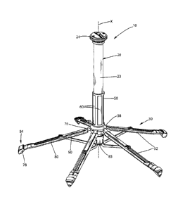
to
the handle sleeve; and a distal end configured to move away from the warning
body upon sliding the handle sleeve downwardly along the at least a portion of
the warning body.
[0008] According to another general aspect, there is provided a warning device
comprising a warning body having a longitudinal axis and comprising a light-
emitting assembly; and a collapsible stand selectively configurable at least
into:
a compacted configuration; and a warning configuration in which the light-
emitting
assembly is at least partially visible. The collapsible stand comprises a
handle
sleeve mounted to and slidable along at least a portion of the warning body;
and
a plurality of legs pivotably mounted to the handle sleeve, the plurality of
legs
being juxtaposed against the warning body when the collapsible stand is
configured in the compacted configuration to at least partially cover the
warning
body and the plurality of legs extending outwardly and downwardly from the
warning body when the collapsible stand is configured in the warning
configuration. The collapsible stand is configurable between the compacted
configuration and the warning configuration by sliding the handle sleeve along
the at least a portion of the warning body.
[0009] According to another general aspect, there is provided a warning
assembly
comprising at least one warning device according the present disclosure; and a
storage box having a housing defining an inner cavity to receive the at least
one
warning device.
[0010] According to another general aspect, there is provided a method of
emitting a warning light signal, comprising providing a warning device
comprising
a light-emitting assembly and a collapsible stand having a handle sleeve
mounted
to and slidable along at least a portion of the light-emitting assembly and a
plurality of legs pivotably mounted to the handle sleeve; sliding the handle
sleeve
downwardly along the at least a portion of the light-emitting assembly for the
plurality of legs to extend outwardly and downwardly from the light-emitting
File No. 19246-5 - 2 -
CA 3053026 2019-08-26
assembly so as to form a warning device stand; and actuating the light-
emitting
assembly to emit a warning light signal.
[0011] According to another general aspect, there is provided a warning device
comprising a warning body having a longitudinal axis and comprising a light-
emitting assembly, and a collapsible stand. The collapsible stand is
configurable
in a compacted configuration, and in a warning configuration in which the
light-
emitting assembly is at least partially visible. The collapsible stand
comprises a
handle sleeve slidably mounted to the warning body; and a plurality of legs
pivotably mounted to the handle sleeve. The plurality of legs are juxtaposed
against the warning body when the collapsible stand is configured in the
compacted configuration to at least partially cover the warning body. The
plurality
of legs extend outwardly and downwardly when the collapsible stand is
configured in the warning configuration. The collapsible stand is configurable
between the compacted configuration and the warning configuration by sliding
the handle sleeve along the warning body.
[0012] According to another general aspect, there is provided a warning device
comprising a warning body having a longitudinal axis and comprising a light-
emitting assembly, and a collapsible stand. The collapsible stand comprises a
handle sleeve slidably mounted along the warning body and a plurality of legs.
Each of the plurality of legs has a proximal end pivotably mounted to the
handle
sleeve, and a distal end configured to move away from the warning body when
the handle sleeve is slid downwardly along the warning body.
[0013] According to yet another general aspect, there is provided a warning
assembly comprising at least one warning device according to the present
disclosure, and a storage box having a housing defining an inner cavity to
receive
the at least one warning device.
BRIEF DESCRIPTION OF THE DRAWINGS
[0014] Fig. 1 is a top perspective view of a warning device in accordance with
an
embodiment, the warning device including a warning body and a collapsible
stand
configured in a warning configuration;
File No. 19246-5 - 3 -
CA 3053026 2019-08-26
[0015] Fig. 2 is a top perspective view of the warning device of Fig. 1,
wherein the
collapsible stand is configured in a compacted configuration;
[0016] Fig. 3 is a side elevation view of the warning device of Fig. 2;
[0017] Fig. 4 is a sectional view of the warning device of Fig. 3, taken along
cross-
section lines A-A of Fig. 3;
[0018] Fig. 5 is a sectional view of the warning device of Fig. 3, wherein the
collapsible stand is configured in the warning configuration;
[0019] Fig. 6 is a side elevation view of the warning device of Fig. 1,
wherein the
collapsible stand is configured in an intermediate configuration between the
compacted configuration and the warning configuration;
[0020] Fig. 7 is a side elevation view of the warning device of Fig. 1,
wherein the
collapsible stand is configured in the warning configuration;
[0021] Figs. 8 and 9 are top perspective views of the warning device of Fig.
1,
wherein the warning body comprises a grabbing portion and the collapsible
stand
includes a handle sleeve that is slid downwardly along at least a portion of
the
warning body for the collapsible stand to be configured from the compacted
configuration to the warning configuration upon manipulation respectively of
the
handle sleeve and the grabbing portion by a user;
[0022] Fig. 10 is a top perspective view of the warning device of Fig. 1,
wherein
the handle sleeve is slid upwardly along the warning body for the collapsible
stand
to be configured from the warning configuration to the compacted
configuration;
[0023] Figs. 11 and 12 are respectively rear and side elevation views of a
light-
emitting module of the warning body of the warning device of Fig. 1, removed
from a translucent sleeve;
[0024] Figs. 13 and 14 are sectional views of the light-emitting module of
Figs. 11
and 12, respectively taken along cross-section lines B-B of Fig. 11 and cross-
section lines C-C of Fig. 12;
File No. 19246-5 -4 -
CA 3053026 2019-08-26
[0025] Fig. 15 is a sectional view of a central portion of the warning device
of Fig.
1, around a base of the handle sleeve, taken along cross-section lines A-A of
Fig.
3;
[0026] Figs. 16 and 17 are enlarged views of a portion of the base of the
handle
sleeve and a proximal end of a leg of the collapsible stand of Fig. 15, the
collapsible stand being respectively configured in the intermediate
configuration
and in the compacted configuration;
[0027] Fig. 18 is a front elevation view of a storage box with warning devices
contained therein, in accordance with an embodiment;
[0028] Fig. 19 is a right perspective view of a wall support in accordance
with an
embodiment;
[0029] Fig. 20 is a right perspective view of the wall support of Fig. 19,
with the
storage box of Fig. 18 being engaged with the wall support;
[0030] Fig. 21 is a top perspective view of a charging base in accordance with
an
embodiment, with the storage box of Fig. 18 being engaged with the charging
base;
[0031] Fig. 22 is a partially exploded view of the warning device of Fig. 1;
[0032] Fig. 23 is an exploded view of an upper portion of the light-emitting
assembly of Fig. 1;
[0033] Fig. 24 is an exploded view of a lower portion of the warning device of
Fig.
1; and
[0034] Fig. 25 is an exploded view of the collapsible stand, with leg-
connecting
rods being removed from the collapsible stand.
DETAILED DESCRIPTION
[0035] In the following description, the same numerical references refer to
similar
elements. Furthermore, for the sake of simplicity and clarity, namely so as to
not
unduly burden the figures with several references numbers, not all figures
contain
File No. 19246-5 - 5 -
CA 3053026 2019-08-26
references to all the components and features, and references to some
components and features may be found in only one figure, and components and
features of the present disclosure which are illustrated in other figures can
be
easily inferred therefrom. The embodiments, geometrical configurations,
materials mentioned and/or dimensions shown in the figures are optional, and
are given for exemplification purposes only.
[0036] Moreover, it will be appreciated that positional descriptions such as
"above", "below", "forward", "rearward" "left", "right" and the like should,
unless
otherwise indicated, be taken in the context of the figures only and should
not be
considered limiting. Moreover, the figures are meant to be illustrative of
certain
characteristics of the warning device and are not necessarily to scale.
[0037] To provide a more concise description, some of the quantitative
expressions given herein may be qualified with the term "about". It is
understood
that whether the term "about" is used explicitly or not, every quantity given
herein
is meant to refer to an actual given value, and it is also meant to refer to
the
approximation to such given value that would reasonably be inferred based on
the ordinary skill in the art, including approximations due to the
experimental
and/or measurement conditions for such given value.
[0038] In the following description, an embodiment is an example or
implementation. The various appearances of "one embodiment," "an
embodiment" or "some embodiments" do not necessarily all refer to the same
embodiments. Although various features may be described in the context of a
single embodiment, the features may also be provided separately or in any
suitable combination. Conversely, although the invention may be described
herein in the context of separate embodiments for clarity, it may also be
implemented in a single embodiment. Reference in the specification to "some
embodiments", "an embodiment", "one embodiment" or "other embodiments"
means that a particular feature, structure, or characteristic described in
connection with the embodiments is included in at least some embodiments, but
not necessarily all embodiments.
File No. 19246-5 - 6 -
CA 3053026 2019-08-26
[0039] It is to be understood that the phraseology and terminology employed
herein is not to be construed as limiting and are for descriptive purpose
only. The
principles and uses of the teachings of the present disclosure may be better
understood with reference to the accompanying description, figures and
examples. It is to be understood that the details set forth herein do not
construe
a limitation to an application of the disclosure.
[0040] Furthermore, it is to be understood that the disclosure can be carried
out
or practiced in various ways and that the disclosure can be implemented in
embodiments other than the ones outlined in the description above. It is to be
understood that the terms "including", "comprising", and grammatical variants
thereof do not preclude the addition of one or more components, features,
steps,
or integers or groups thereof and that the terms are to be construed as
specifying
components, features, steps or integers. If the specification or claims refer
to "an
additional" element, that does not preclude there being more than one of the
additional element. It is to be understood that where the claims or
specification
refer to "a" or "an" element, such reference is not be construed that there is
only
one of that element. It is to be understood that where the specification
states that
a component, feature, structure, or characteristic "may", "might", "can" or
"could"
be included, that particular component, feature, structure, or characteristic
is not
required to be included.
[0041] The descriptions, examples, methods and materials presented in the
claims and the specification are not to be construed as limiting but rather as
illustrative only. Meanings of technical and scientific terms used herein are
to be
commonly understood as by one of ordinary skill in the art to which the
invention
belongs, unless otherwise defined. It will be appreciated that the methods
described herein may be performed in the described order, or in any suitable
order.
[0042] Referring now to the drawings, and more particularly to Figs. 1 to 10,
there
is shown a warning device 10 that is configured to be easily, quickly and
stably
installed so as to warn, for instance and without being limitative, road users
of an
accident, an obstacle or any other potential danger or breakdown on a road.
File No. 19246-5 - 7 -
CA 3053026 2019-08-26
[0043] The warning device 10 according to the present disclosure comprises a
warning body 20 extending along a longitudinal axis X. The warning body 20
comprises a light-emitting assembly 22, as represented in Figs. 4 and 5. The
warning device 10 further comprises a collapsible stand 30 configurable in a
compacted configuration (or storage configuration or transport configuration),
as
represented for instance in Fig. 2, and in a warning configuration (or usage
configuration or deployed configuration), as represented for instance in Fig.
1, in
which the light-emitting assembly 22 of the warning body 20 is at least
partially
visible. The term "visible" should be understood as meaning that a light
emitted
by the light-emitting assembly 22 could be seen by a user in the vicinity of
the
warning device 10. In other words, in the warning configuration, the light-
emitting
assembly 22 is not covered by one or more components of the warning device
that would be made in a substantially masking or opaque material. It should
further be understood that, in the warning configuration, the light-emitting
assembly 22 could, as in the embodiment shown, be at least partially covered
by
a component of the warning device 10 at least partially made of a
substantially
translucent material.
[0044] The collapsible stand 30 is also configurable into a plurality of
intermediate
configurations, between the warning configuration and the compacted
configuration, as represented for instance in Figs. 6 and 8 to 10.
Warning body
[0045] As represented in Fig. 4, considered along the longitudinal axis X, the
warning body 20 comprises a sleeve 23 (or body sleeve 23), which is
substantially
cylindrical in shape in the embodiment shown. The body sleeve 23 extends along
the longitudinal axis X and has a substantially constant cross-section. The
warning body 20 also includes a grabbing portion 24, mounted to an upper end
27 of the sleeve 23, and a lower end cap 85 secured to a lower end 31 of the
sleeve 23, as represented in Fig. 4.
[0046] In the following description, the terms lower and upper should be
understood with reference to the longitudinal axis X of the warning body 20,
when
the collapsible stand 30 is configured in the warning configuration, the
warning
File No. 19246-5 - 8 -
CA 3053026 2019-08-26
body 20 being supported on a substantially horizontal ground, such as a road,
so
that the warning body 20 (and the longitudinal axis X thereof) extends in a
substantially vertical orientation.
[0047] As represented in Fig. 4, the sleeve 23 (or body sleeve 23) can be
divided
along its length into an upper section 25 (or upper portion 25) and a lower
section
26 (or lower portion 26). In the embodiment shown, at least the upper section
25
of the sleeve 23 is made of a material having translucent properties, such as
translucent glass or plastics. In the following description, the upper and
lower
sections (or upper and lower portions) of the body sleeve 23 might also be
referred to as the upper and lower sections or upper and lower portions of the
warning body 20.
[0048] The lower section 26 of the body sleeve 23 can also be made of a
material
having translucent properties. However, in the embodiment shown, it is made of
an opaque material.
[0049] In the embodiment shown, an outer surface of the sleeve 23 extends
continuously between the upper section 25 and the lower section 26. The upper
section 25 and the lower section 26 could also be formed of two distinct
sleeves
secured to each other. For instance, in an embodiment (not shown), each of the
upper section 25 and the lower section 26 of the sleeve 23 could comprise a
sleeve securable together, for instance removably securable to each other by
screws, complementary threads or a ratchet system or being permanently
bonded together.
[0050] The sleeve 23 of the warning body 20 defines an inner channel 37 (or
light-
emitting assembly-receiving cavity 37) configured to contain the light-
emitting
assembly 22 and, more particularly, to contain a light-emitting module 32 and
an
energy supply 40 of the light-emitting assembly 22.
[0051] Referring now to Fig. 4, in the non-limitative embodiment shown, the
inner
channel 37 contains an inner sleeve 36 in the lower section 26 of the body
sleeve
23. In the embodiment shown, the inner sleeve 36 is substantially cylindrical
in
shape and has an outer cross-section corresponding substantially to an inner
File No. 19246-5 - 9 -
CA 3053026 2019-08-26
cross-section of the body sleeve 23, so that the inner sleeve 36 is snugly
fitted
into the lower section 26 of the body sleeve 23. The inner sleeve 36 defines
an
inner cavity 38. In the embodiment shown, the inner cavity 38 is substantially
cylindrical in shape also and extends along the longitudinal axis X. The inner
cavity 38 of the inner sleeve 36 arranged in the lower section 26 of the body
sleeve 23 is configured to contain the energy supply 40 of the light-emitting
assembly 22. In the embodiment shown, the energy supply 40 is a battery
assembly 40 (for instance a rechargeable battery assembly 40) and comprises
two batteries 42 (for instance two rechargeable batteries 42) extending
consecutively along the longitudinal axis X in the inner cavity 38 of the
inner
sleeve 36. It is appreciated that the shape, the configuration, and the
location of
the energy supply 40, as well as the configuration and the number of the
batteries
42 can vary from the embodiment shown.
[0052] It is appreciated that the shape and the configuration of the body
sleeve
23, as well as the shape and the configuration of its inner channel 37 as well
as
the shape and the configuration of the inner sleeve 36, can vary from the
embodiment shown. It could also be conceived a warning body 20 having no inner
sleeve arranged in the lower section of the body sleeve 23 (i.e. a warning
body
20 in which the energy supply 40 of the light-emitting assembly 22 would be
arranged directly in the inner channel 37 of the body sleeve 23).
Light-emitting module
[0053] The light-emitting module 32 of the light-emitting assembly 22 is
removably
inserted into the upper portion 25 of the inner channel 37 defined in the
sleeve
23. A non-limitative embodiment of the light-emitting module 32 is shown in
Figs.
11 to 14, wherein the light-emitting assembly 22 has been removed from the
body
sleeve 23.
[0054] The light-emitting module 32 has an upper end 28 and an opposed lower
end 29. In the embodiment shown, the upper end 28 of the light-emitting module
32 is substantially horizontally aligned with the upper end 27 of the sleeve
23
when inserted therein, considered along the longitudinal axis X. As described
below, the grabbing portion 24 is mounted to the upper end 28 of the light-
emitting
File No. 19246-5 - 10 -
CA 3053026 2019-08-26
module 32, as represented in Fig. 4 and is engaged to a portion of the upper
end
27 of the body sleeve 23 surrounding at least partially the upper end 28 of
the
light-emitting module 32.
[0055] In the embodiment shown, the light-emitting module 32 comprises a
translucent peripheral wall 39, extending at least along an axial section
thereof,
and a plurality of light sources 33, such as LEDs, housed therein. It is
understood
that the body sleeve 23, in particular its translucent areas, is arranged with
regards to the light-emitting assembly 22 for the lights emitted by the light
sources
33 of the light-emitting module 32 to be visible from the outside of the
warning
body 20 at least when the collapsible stand 30 is configured in the warning
configuration. In the embodiment shown, the translucent peripheral wall 39 has
an outer surface presenting a substantially serrated profile, designed to
contribute
to the diffusion of the light emitted by the light sources 33 of the light-
emitting
assembly 22. In the embodiment shown, the translucent peripheral wall 39 acts
as a lens for the light sources 33 contained therein. In some embodiments, the
outer surface of the light-emitting module 32 could have a Fresnel surface
structure, so as to further improve the diffusion of the lights emitted by the
light
sources 33 of the light-emitting module 32.
[0056] As represented in Figs. 7 and 13, the light-emitting module 32 further
comprises an actuator 34 electrically coupled to the light sources 33. In the
embodiment shown, the actuator 34 comprises an infrared sensor which function
will be better understood thereafter.
[0057] In the embodiment shown, as represented for instance in Figures 4 and
5,
the lower end 29 of the light-emitting module 32 is electrically couplable to
an
upper end of the battery assembly 40 (or energy supply 40), and more
particularly
electrically couplable to one of the rechargeable batteries 42 extending in
the
inner cavity 38 defined in the lower section 26 of the body sleeve 23, so that
the
battery assembly 40 provides power to the light-emitting module 32.
[0058] It is appreciated that the shape and the configuration of the light-
emitting
assembly 22, as well as the structure of the light-emitting module 32 and the
configuration and the location of the actuator 34 and the number, the
File No. 19246-5 -11 -
CA 3053026 2019-08-26
configuration, and the location of the light sources 33 can vary from the
embodiment shown.
Grabbing portion
[0059] As represented for instance in Figs. 11 to 14 and 23, in the embodiment
shown, the grabbing portion 24 of the warning body 20 is mounted to the upper
end 28 of the light-emitting module 32. When the light-emitting module 32 is
inserted into the inner channel 37 of the body sleeve 23, the grabbing portion
24
is juxtaposed to the upper end 27 of the body sleeve 23 and engaged therewith.
More particularly, at a lower end 19 of the grabbing portion 24, a sleeve-
engaging
cavity 17 is formed in the grabbing portion 24; the sleeve-engaging cavity 17
is
delimited in the grabbing portion 24 by an inner peripheral wall. The upper
end
28 of the light-emitting module 32 is at least partially inserted into the
sleeve-
engaging cavity 17. In the embodiment shown, when the grabbing portion 24 is
mounted to the light-emitting module 32 by insertion of the translucent
peripheral
wall 39 of the light-emitting module 32 into the sleeve-engaging cavity 17 of
the
grabbing portion 24, an annular channel is defined between the inner
peripheral
wall of the grabbing portion 24 and the translucent peripheral wall 39 of the
light-
emitting module 32. The annular channel is accessible adjacent to the lower
end
19 of the grabbing portion 24. The inner peripheral wall of the grabbing
portion
24 delimitating outwardly the annular channel has a thread 21 formed thereon.
The thread 21 is configured to cooperate with a corresponding thread 41
(Figures
4 and 22) formed on an outer surface of the upper end 27 of the body sleeve
23.
[0060] As represented in Figs. 13, 14 and 22, in the embodiment shown, the
grabbing portion 24 comprises an upper grabbing element 24a and a lower
grabbing element 24b engageable together (for instance via screws or any other
mechanical fasteners). As represented in Fig. 22, once the different
components
of the light-emitting module 32 are assembled together, the upper grabbing
element 24a is mounted to the upper end 28 of the light-emitting module 32
while
the lower grabbing element 24b is slid upwardly along the translucent
peripheral
wall 39 from the lower end 29 towards the upper end 28 of the light-emitting
module 32, for an upper mounting ring extending outwardly from the translucent
File No. 19246-5 - 12 -
CA 3053026 2019-08-26
peripheral wall 39 to be sandwiched between the upper and lower grabbing
elements 24a, 24b of the grabbing portion 24. In the embodiment shown, the
sleeve-engaging cavity 17 is at least partially formed in the lower grabbing
element 24b and between the upper and lower grabbing elements 24a, 24b.
[0061] The grabbing portion 24 can thus be easily detached from the body
sleeve
23 (from the upper end 27 thereof, in the embodiment shown), so as to provide
access to the light-emitting assembly 22, and more particularly access to the
light-
emitting module 32 thereof. Moreover, the grabbing portion 24 is easily
detachable from the light-emitting module 32 so as to provide access to its
different components.
[0062] In another embodiment (not shown), the lower end cap 85 of the warning
body 20 could be removably mounted to the lower end 31 of the body sleeve 23
so as to easily provide access to the lower section of the light-emitting
assembly
22 (for instance, to the energy supply 40 thereof) contained in the inner
channel
37 of the body sleeve 23.
[0063] In the embodiment shown, as represented in Fig. 3, the grabbing portion
24 has an outer cross-section d4 (or outer diameter 24 in the embodiment in
which the upper grabbing element 24a has a substantially circular shape or
outer
grabbing diameter d4) (considered in a direction substantially perpendicular
to
the longitudinal axis X) greater than an outer cross-section d3 (or outer
diameter
d3, in the embodiment in which the body sleeve 23 has a substantially
cylindrical
shape, or outer body sleeve diameter d3) of the body sleeve 23, also
considered
in a direction substantially perpendicular to the longitudinal axis X, so as
to ease
the grabbing of the warning device 10 by a user. In some embodiments, the
outer
diameter d4 of the grabbing portion 24 is at least about 10% greater than the
outer diameter d3 of the body sleeve 23. In some other embodiments, the outer
diameter d4 of the grabbing portion 24 is at least about 20% greater than the
outer diameter d3 of the body sleeve 23. In yet some other embodiments, the
outer diameter d4 of the grabbing portion 24 is at least about 40% greater
than
the outer diameter d3 of the body sleeve 23.
File No. 19246-5 - 13 -
CA 3053026 2019-08-26
[0064] The grabbing portion 24 could alternatively be formed integral with at
least
one of the body sleeve 23 and the light-emitting assembly 22 (for instance
formed
integral with the upper end 28 of the light-emitting module 32).
[0065] In the embodiment shown, the grabbing portion 24 can be considered as
being part of the light-emitting assembly 22 since the grabbing portion 24 is
electrically coupled to the battery assembly 40 via the lower end 29 of the
light-
emitting assembly 22 and further comprises a battery charge indicator 47
configured to indicate a level of charge of the battery assembly 40, as
represented in Figs. 11 to 14.
[0066] In the embodiment shown, the grabbing portion 24 further comprises an
electric port 44, for instance on a rear portion thereof, couplable ¨ directly
or
indirectly - to a power source and thus configured to electrically couple the
battery
assembly 40 to the power source, so as to provide power to the rechargeable
battery assembly 40, i.e. to recharge the rechargeable battery assembly 40.
[0067] It is thus understood that in the embodiment shown, the grabbing
portion
24, the light-emitting module 32 and the energy supply 40 are electrically
coupled
together for the warning body 20 to generate a light signal, such as a warning
light signal, at least when the collapsible stand 30 is configured in the
warning
configuration. More particularly, the grabbing portion 24 is electrically
coupled to
the upper end 28 of the light-emitting module 32, whereas the energy supply 40
(or the battery assembly 40, in the embodiment shown) is electrically coupled
to
the lower end 29 of the light-emitting module 32, for the batteries 42 of the
energy
supply 40 to supply power to the light-emitting module 32, for its light
sources 33
to generate the warning light signal.
[0068] It is appreciated that the shape and the configuration of the grabbing
portion 24, as well as the shape, the configuration and the number of its
elements
can vary from the embodiment shown. Furthermore, in an alternative
embodiment, the grabbing portion 24 could be exempt of electrical features and
solely close the inner channel of the sleeve 23.
Collapsible stand
File No. 19246-5 - 14 -
CA 3053026 2019-08-26
[0069] As represented in Figs. 1 to 10 and in Fig. 25, the collapsible stand
30
comprises a handle sleeve 50 mounted to and slidable along the warning body
20 (at least slidable along an axial portion thereof, for instance slidable
along an
axial portion of the translucent sleeve 23, in the embodiment shown), and a
plurality of legs 52 pivotably mounted to the handle sleeve 50. As represented
in
Figs. 2 and 3, the plurality of legs 52 are juxtaposed against the warning
body 20
when the collapsible stand 30 is configured in the compacted configuration to
at
least partially cover the warning body 20. It is thus understood that, when
the
collapsible stand 30 is configured in the compacted configuration, the warning
device 10 has substantially the shape of a baton or a stick.
[0070] When the collapsible stand 30 is configured in the warning
configuration,
as represented for instance in Fig. 1, the plurality of legs 52 extend
outwardly and
downwardly from the handle sleeve 50. In the following description, the term
outwardly should be understood with regard to the inner channel 37 defined by
the sleeve 23 (or body sleeve 23) of the warning body 20.
[0071] As detailed below, the collapsible stand 30 is configurable between the
compacted configuration and the warning configuration by sliding the handle
sleeve 50 along at least an axial ¨ or longitudinal ¨ portion of the warning
body
20.
Handle sleeve
[0072] As represented for instance in Fig. 3, the handle sleeve 50 is slidably
mounted to the sleeve 23 of the warning body 20 and surrounds same. The
handle sleeve 50 has a body 54 (or handle body 54) defining an inner channel,
which shape substantially conforms to an outer shape of the body sleeve 23. In
the embodiment shown, the body 54 is substantially annular or cylindrical to
define a substantially cylindrical inner channel. It could however be
conceived a
warning device 10 having a handle sleeve 50 and a body sleeve 23 which would
not have a substantially cylindrical shape, as long as the handle sleeve 50
and
the body sleeve 23 would be shaped and dimensioned to slide along each other.
The body 54 of the handle sleeve 50 has an outer surface 56. The handle sleeve
50 further includes a handle base 58 (or base 58) protruding outwardly in a
lower
File No. 19246-5 - 15 -
CA 3053026 2019-08-26
section thereof. The base 58 can be mounted to or be integral with the
cylindrical
body 54.
[0073] In the embodiment shown, as represented in Fig. 15, the handle base 58
comprises two complementary portions 62, 64 secured to each other, by
mechanical fasteners 66 such as screws.
[0074] The handle sleeve 50 is coaxial with the body sleeve 23 of the warning
body 20. The handle body 54 of the handle sleeve 50 has an inner cross-section
dl (or inner diameter dl, in the embodiment in which the handle body 54 is
substantially cylindrical in shape), as represented in Figs. 5 and 15, that is
equal
to or slightly larger than an outer cross-section d2 of the sleeve 23 (or
outer
diameter d2, in the embodiment in which the sleeve is substantially
cylindrical in
shape), so that the handle sleeve 50 is slidable along the outer surface of
the
sleeve 23 along the longitudinal axis X.
[0075] In the embodiment shown, as represented for instance in Fig. 1, the
handle
sleeve 50 comprises luminescent strips 60, for instance substantially
rectangular,
mounted to the outer surface 56 of the handle body 54. The luminescent strips
60 are configured to reflect light, so as to increase the visibility of the
warning
device 10. It is appreciated that the shape and the configuration of the
luminescent strips 60 can vary from the embodiment shown. It could also be
conceived a warning device 10 having no luminescent strips 60 on the outer
surface of the handle sleeve 50 and/or having luminescent strips 60 arranged
on
other parts of the warning device 10 (for instance on an outer surface of one
or
more of the legs 52).
[0076] The outer surface 56 of the body 54 might further comprise handling
portions configured to ease the handling of the handling sleeve 50, and thus
ease
the handling of the warning device 10.
[0077] Turning now to Figures 15 to 17, there is shown that the base 58 of the
handle sleeve 50 further comprises a blocking assembly 68, comprising, in the
embodiment shown, a blocking ring 70 extending circumferentially around the
outer surface of the body sleeve 23 of the warning body 20. In the embodiment
File No. 19246-5 - 16 -
CA 3053026 2019-08-26
shown, as represented in Figs. 15 to 17, the blocking ring 70 of the blocking
assembly 68 also comprises a bendable (or deflectable) portion 74 including a
receiving recess 72 defined on an outer surface of the blocking ring 70, which
functions will be described thereafter. In the embodiment shown, the blocking
ring
70 is formed by a portion of the lower complementary portion 64 of the base
58.
In the embodiment shown, the lower complementary portion 64 has a thickness
varying along its periphery. It is however appreciated that the shape and
configuration of the blocking assembly 68 and of its blocking ring 70 can vary
from the embodiment shown.
[0078] It is also appreciated that the shape and the configuration of the
handle
sleeve 50 can vary from the embodiment shown.
Legs
[0079] As represented in particular in Figs. 1, 4, 6 and 7, the collapsible
stand 30
comprises a plurality of legs 52 (five, in the embodiment shown) angularly
spaced-apart from each other. The number of legs 52 can obviously differ from
the embodiment shown. In the embodiment shown, the five legs 52 are
substantially regularly spaced-apart from each other when the collapsible
stand
30 is configured in the warning configuration.
[0080] In the embodiment shown, the legs 52 have a similar shape, so that the
following description of one of the legs 52 will apply to any of them.
[0081] The leg 52 has a leg body 80 extending between a proximal end 76 and a
distal end 78.
[0082] At its proximal end 76, the leg 52 is pivotally mounted to the handle
sleeve
50 about a pivot axis X1. In the embodiment shown, the pivot axis X1 extends
substantially perpendicularly to the longitudinal axis X of the warning body
20.
[0083] In the embodiment shown, the proximal end 76 is pivotally mounted about
the pivot axis X1 to the base 58 of the handle sleeve 50. For instance, as
represented in Fig. 15, the proximal end 76 of the leg 52 is mounted between
the
two complementary portions 62, 64 forming the base 58.
File No. 19246-5 - 17 -
CA 3053026 2019-08-26
[0084] As represented in Figs. 15 to 17, the proximal end 76 comprises a
protrusion 82 protruding outwardly and towards the handle sleeve 50. The
protrusion 82 is dimensioned to be received in the receiving recess 72 defined
in
the outer surface of the blocking ring 70 of the blocking assembly 68.
[0085] As represented in Fig. 1, the distal end 78 is spaced apart ¨ moved
away
- from the warning body 20 when the collapsible stand 30 is configured in the
warning configuration.
[0086] In some embodiments, as represented in Fig. 5, the leg 52 forms an
angle
a with the lower section 26 of the sleeve 23 of the warning body 20 (or with
the
longitudinal axis X of the warning body 20) comprised between about 15 and
about 180 when the collapsible stand 30 is configured in the warning
configuration. In some other embodiments, the angle a is comprised between
about 30 and about 150 when the collapsible stand 30 is configured in the
warning configuration. In some other embodiments, the angle a is comprised
between about 60 and about 120 when the collapsible stand 30 is configured
in the warning configuration. In some other embodiments, the angle a is
comprised between about 80 and about 100 when the collapsible stand 30 is
configured in the warning configuration.
[0087] The distal end 78 of the leg 52 comprises a leg cap 84. In the
embodiment
shown, the leg cap 84 is at least partially made of a material having some
absorbent characteristics, such as elastomeric material or TPR (trans-
polypentenamer natural rubber).
[0088] The leg caps 84 of the different legs 52 of the collapsible stand 30
are
configured to form together, when the collapsible stand 30 is configured in
the
compacted configuration, a protection cap 86, as represented in Fig. 2,
covering
at least partially the lower end 31 of the sleeve 23 of the warning body 20
and the
lower end cap 85 of the warning body 20.
[0089] It is appreciated that the shape, the configuration, the number, and
the
location of the legs 52 with regards to the handle sleeve 50 and to the
warning
body 20 can vary from the embodiment shown.
File No. 19246-5 - 18 -
CA 3053026 2019-08-26
Leq-connectind rods (or lea deployment-limitinq rods)
[0090] The collapsible stand 30 further comprises a plurality of leg-
connecting
rods 90 (or leg deployment-limiting rods 90) connecting each one of said
plurality
of legs 52 to the warning body 20. As detailed below, the leg-connecting rods
90
are configured to limit the deployment of the legs 52 when the collapsible
stand
30 is configured in the warning configuration.
[0091] In the embodiment shown, the leg-connecting rods 90 have a similar
shape, so that the following description of one of the leg-connecting rods 90
will
apply to any of them.
[0092] The leg-connecting rod 90 comprises a proximal end 92 pivotably mounted
to the lower portion 26 of the warning body 20 about a pivot axis X2. The leg-
connecting rod 90 further comprises a distal end 94 pivotably mounted to one
of
the legs 52 about a pivot axis X3. In the embodiment shown, the proximal end
92
of the leg-connecting rod 90 is mounted to the lower end cap 85 of the warning
body 20, the pivot axis X2 being for instance sandwiched between different
components forming the lower end cap 85, as represented in Fig. 25.
[0093] In the embodiment shown, the pivot axes X2 and X3 of the proximal end
92 and the distal end 94 are substantially parallel to each other. In the
embodiment shown, the pivot axes X2 and X3 are substantially parallel to the
pivot axis X1 of the legs 52, and are thus substantially perpendicular to the
longitudinal axis X of the warning body 20.
[0094] The leg-connecting rod 90 further comprises a body 96 (or rod body 96)
extending between the proximal and distal ends 92, 94. In the embodiment
shown, as represented for instance in Fig. 24 the rod body 96 comprises
proximal
and distal portions 97, 99 (or proximal and distal end portions 97, 99
comprising
respectively the proximal and distal ends 92, 94) angled relative to each
other,
but a rod body 96 having a single straight portion could obviously also be
conceived.
File No. 19246-5 - 19 -
CA 3053026 2019-08-26
[0095] In the embodiment shown, the distal end 94 is pivotably mounted about
the pivot axis X3 to a central portion of the longitudinal body 80 of the
corresponding leg 52.
[0096] In the embodiment shown, the leg-connecting rod 90 extends along the
lower portion 26 of the warning body 20 when the collapsible stand 30 is
configured in the compacted configuration, as represented in Fig. 4. In the
embodiment shown, as represented for instance in Fig. 6, a rod-receiving slot
51
(or rod-receiving groove 51) is formed in the leg 52 (for instance in the leg
body
80 thereof). The rod-receiving slot 51 is shaped and dimensioned to receive at
least partially the corresponding leg-connecting rod 90 when the collapsible
stand
30 is configured in the compacted configuration.
[0097] In some embodiments, as represented in Fig. 5, the leg-connecting rod
90
(its proximal end portion 97, in the embodiment shown) forms an angle p with
the
lower portion 26 of the sleeve 23 of the warning body 20 (or with the
longitudinal
axis X of the warning body 20, in the embodiment shown) comprised between
about 15 and about 150 when the collapsible stand 30 is configured in the
warning configuration. In some other embodiments, the angle p is comprised
between about 30 and about 130 when the collapsible stand 30 is configured
in the warning configuration. In yet some other embodiments, the angle p is
comprised between about 60 and about 120 when the collapsible stand 30 is
configured in the warning configuration. It is thus understood that the leg-
connecting rod 90 is configured to limit the outward and downward displacement
of the leg 52, when the collapsible stand 30 is configured in the warning
configuration.
[0098] In the embodiment shown, the leg-connecting rod 90 is made of metal,
such as aluminum, so as to limit a total weight of the warning device 10.
[0099] It is appreciated that the shape, the configuration, the number and the
location of the leg-connecting rods 90 with regards to the legs 52 and to the
warning body 20 can vary from the embodiment shown.
Method for installing the warning device
File No. 19246-5 - 20 -
CA 3053026 2019-08-26
[00100] It is understood that the warning device 10 according to
the present
disclosure is configured to be easily stored and/or transported, when the
collapsible stand 30 is configured in the compacted configured. The warning
device 10 is further configured to be easily and stably deployed so as to
provide
an efficient warning light signal, when the collapsible stand 30 is configured
in the
warning configuration. The warning device 10 is also configured for the
collapsible stand 30 to be easily, effortlessly and quickly configured from
one of
the compacted and warning configurations to the other.
[00101] Referring more particularly to Figs. 2 and 3, when the
collapsible
stand 30 is configured in the compacted configuration, the warning device 10
can
be easily transported and stored and only requires a limited storage space.
When
the collapsible stand is configured in the compacted configuration, the legs
52
substantially extend along the lower portion 26 of the warning body 20 and at
least partially cover same.
[00102] In the embodiment shown, the legs 52, and more particularly
their
leg bodies 80, are dimensioned and shaped so as to be in close cooperation
with
the outer surface of the body sleeve 23 of the warning body 20, and more
particularly with the lower section 26 of the sleeve 23 of the warning body
20. It
is thus understood that the legs 52 form a protective layer surrounding at
least
partially the warning body 20, and more particularly surrounding at least
partially
the lower section 26 of the sleeve 23, so as to protect the light-emitting
assembly
22 of the warning body 20.
[00103] In some embodiments, as represented in Fig. 3, the legs 52
have a
length L1 considered along the longitudinal axis X when the collapsible stand
30
is configured in the compacted configuration. The length L1 extends along at
least
about 30% of a length L2 of the warning body 20, also considered along the
longitudinal axis X. In some other embodiments, the length L1 of the legs 52
extends along at least about 50% of the length L2 of the warning body 20. In
yet
some other embodiments, the length L1 of the legs 52 extends along at least
about 70% of the length L2 of the warning body 20.
File No. 19246-5 - 21 -
CA 3053026 2019-08-26
[00104] In some embodiments, the length L2 of the warning body 20 is
comprised between about 20 cm and about 60 cm. In some other embodiments,
the length L2 of the warning body 20 is comprised between about 30 cm and
about 40 cm.
[00105] When the collapsible stand 30 is configured in the compacted
configuration, the handle sleeve 50 at least partially covers the light-
emitting
assembly 22 of the warning body 20. In the embodiment shown, the handle
sleeve 50 is dimensioned so as to substantially cover the light-emitting
module
32 of the light-emitting assembly 22.
[00106] In some embodiments, as represented in Fig. 3, the handle
sleeve
50 has a length L3 considered along the longitudinal axis X. The length L3
extends along at least about 10% of the length L2 of the warning body 20. In
some other embodiments, the length L3 of the handle sleeve 50 extends along
at least about 20% of the length L2 of the warning body 20. In yet some other
embodiments, the length L3 of the handle sleeve 50 extends along at least
about
30% of the length L2 of the warning body 20.
[00107] As represented in Fig. 6, when the collapsible stand 30 is
configured in the compacted configuration, an outer diameter d5 of the
plurality
of the legs 52 surrounding the warning body 20 (for instance an outer diameter
d5 ¨ or outer cross-section - of the distal ends 78 of the legs 52 when the
collapsible stand 30 is configured in the compacted configuration), considered
transversally to the longitudinal axis X, is substantially equal to the outer
diameter
d4 ¨ or outer cross-section d4 - of the grabbing portion 24 of the warning
body
20.
[00108] Moreover, the cooperation of the protrusions 82 of the legs
52 with
the receiving recesses 72 of the blocking assembly 68 of the handle sleeve 50
prevents any unintentional pivoting of the legs 52 about the pivot axis X1
when
the collapsible stand 30 is configured in the compacted configuration.
[00109] Referring now more particularly to Figs. 1 and 5, when the
collapsible stand 30 is configured in the warning configuration, the distal
ends 78
File No. 19246-5 - 22 -
CA 3053026 2019-08-26
of the legs 52 are angularly spaced from each other so as to ensure a stable
support to the warning body 20.
[00110] In other words, when the collapsible stand 30 is configured
in the
warning configuration, the legs 52 are spaced-apart from one another and
extend
radially about the warning body 20 to support the warning body 20 in a
substantially upright position. As represented in Fig. 7, when the collapsible
stand
30 is configured in the warning configuration, the legs 52 form a support base
having a width W1 considered transversally to the longitudinal axis X that is
substantially equal or even greater than the length L2 of the warning body 20.
In
some embodiments, the width W1 of the deployed legs 52 (or width W1 of the
collapsible stand 30) is comprised between about 25 cm and about 60 cm. In
some other embodiments, the width W1 is comprised between about 40 cm and
about 50 cm.
[00111] As represented in Fig. 7, the legs 52 are arranged so that
the
warning device 10 has a length L5, considered along a direction substantially
parallel to the longitudinal axis X of the warning body 20, that is greater,
when the
collapsible stand 30 is configured in the warning configuration, than the
length L2
of the warning body 20. The arrangement of the legs 52 thus further
contributes
to the visibility of the light-emitting module 32, and thus to the efficiency
of the
warning device 10.
[00112] It is to be noted that the arrangement of the battery
assembly 40 in
the lower section 26 of the sleeve 23 of the warning body 20, by lowering the
gravity center of the warning device 10, contributes to the stability of the
warning
device 10 when the collapsible stand 30 is configured in the warning
configuration.
[00113] Referring now more particularly to Figs. 8 and 9, the
warning device
is configured so that the collapsible stand 30 can be easily configured from
the compacted configuration in the warning configuration.
[00114] As represented in Fig. 8, the user grabs the handle sleeve
50 and
pulls upwardly the grabbing portion 24, so as to slide the handle sleeve 50
File No. 19246-5 - 23 -
CA 3053026 2019-08-26
downwardly along the sleeve 23 of the warning body 20. In other words, by
using
one single hand and exerting a pressure by a finger (for instance by a thumb),
the user can easily slide downwardly the handle sleeve 50 with regard to the
grabbing portion 24, so as to configure the collapsible stand 30 from the
compacted configuration into the warning configuration.
[00115] By doing so, the leg-connecting rods 90 start pivoting
outwardly
about the pivot axis X3 and make the legs 52 start pivoting outwardly about
the
pivot axis X1. As represented in Fig. 16, for the legs 52 to start pivoting, a
force
sufficient to bend inwardly the bendable portion 74 of the blocking assembly
68
of the handle sleeve 50 has to be exerted, so that the protrusion 82 of the
legs
52 can be released from the receiving recess 72 (or blocking recess 72).
[00116] As represented in Fig. 9, the deployment of the legs 52 is
pursued
by the handle sleeve 50 further sliding downwardly along the sleeve 23 of the
warning body 20. In the embodiment shown, the legs 52 and/or the handle sleeve
50 are shaped and dimensioned so that the handle sleeve 50 easily slides along
the sleeve 23 of the warning body 20 once the sliding has been initiated.
[00117] The sliding of the handle sleeve 50 downwardly along the
sleeve
23 of the warning body 20 further makes the light-emitting module 32 of the
warning body 20 visible. In the embodiment shown, the actuator 34 is
configured
to automatically actuate the light-emitting module 32 once the handle sleeve
50
has been slid downwardly along a pre-determined length of the sleeve 23 of the
warning body 20. The actuator 34 thus contributes to the efficiency of the
warning
device 10, by ensuring that a light (or warning light signal) is automatically
emitted
when the handle sleeve 50 has been sufficiently downwardly slid along the
warning body 20. It thus contributes to limit the time required to install the
warning
device 10. Moreover, the actuator 34 is configured to limit the risk that
lights are
unnecessarily emitted when the collapsible stand 30 is configured in the
compacted configuration, so as to limit the loss of power by the battery
assembly
40.
[00118] It is to be noted that only a few seconds are required for
the user to
configure the collapsible stand 30 from the compacted configuration to the
File No. 19246-5 - 24 -
CA 3053026 2019-08-26
warning configuration, and thus to install the warning device 10 and emit a
warning light signal. In some embodiments, less than 3 seconds are required to
install the warning device 10.
[00119] Referring now more particularly to Fig. 10, the warning
device 10 is
configured so that the collapsible stand 30 can be easily configured from the
warning configuration in the compacted configuration.
[00120] To do so, the used holds the handle sleeve 50 and slide it
upwardly
along the warning body 20, towards the grabbing portion 24. In the embodiment
shown, the legs 52 and/or the leg-connecting rods 90 are shaped and
dimensioned so as to automatically pivot inwardly towards the lower section 26
of the sleeve 23 of the warning body 20 when the handle sleeve 50 is slid
upwardly towards the grabbing portion 24.
[00121] The cooperation of the protrusions 82 of the legs 52 with
the
receiving recess 72 (or blocking recess 72) of the blocking assembly 68 of the
handle sleeve 50 ensures the blocking of the legs 52 in a position in which
they
substantially extend along the lower section 26 of the sleeve 23 of the
warning
body 20.
[00122] In an embodiment (not shown), the handle sleeve 50 is
configured
to cooperate with the warning body 20, for instance with the grabbing portion
24,
so as to further maintain the collapsible stand 30 configured in the compacted
cooperation and to limit the risk of the collapsible stand 30 being
accidentally
configured in the warning configuration.
Warning assembly
[00123] The present disclosure also concerns a warning assembly 200
comprising one or more warning devices 10 and different accessories.
Storage box
[00124] In the embodiment shown, as represented in Fig. 18, the
warning
assembly 200 comprises a storage box 210 having a storage housing 212
File No. 19246-5 - 25 -
CA 3053026 2019-08-26
defining a cavity 215 dimensioned to receive a plurality of warning devices 10
(three in the embodiment shown, but could be dimensioned to contain more or
less warning devices 10).
[00125] The storage housing 212 comprises a charging portion 213 (or
box
charging portion 213) configured to cooperate with the grabbing portions 24 of
the warning devices 10 received in the cavity 215, and more particularly with
the
electric ports 44 of the warning devices 10.
[00126] The storage box 210 further comprises a handling portion 214
to
ease the handling and transport of the storage box 210, and an electric port
216
(or box electric port 216) to cooperate with a power source (not represented)
to
charge the warning devices 10 via the charging portion 213 and the electric
ports
44 of the grabbing portions 24 of the warning devices 10.
Wall support
[00127] In the embodiment shown, as represented in Figs. 19 and 20,
the
warning assembly 200 can further comprise a wall support 220, configured to be
secured to a wall portion, for instance in a vehicle. The wall support 220
comprises support portions 222 defining together a box-receiving cavity 224
dimensioned to receive, in the embodiment shown, the storage box 210.
[00128] The wall support 220 further comprises a support belt 226 to
securely maintain the storage box 210 in the box-receiving cavity 224, as
represented in Fig. 20.
[00129] In the embodiment shown, the wall support 220 also comprises
an
electric port 228 (or support electric port 228) to cooperate with a power
source
(not represented) to charge the warning devices 10 contained in the storage
box
210. More particularly, the electric port 228 is operatively connected to the
electric
port 216 of the storage box 210 when the storage box 210 is located in the box-
receiving cavity 224 of the wall support 220. It is thus understood that the
storage
box 210 forms a charging interface between the warning devices 10 and the wall
support 220.
File No. 19246-5 - 26 -
CA 3053026 2019-08-26
Charging base
[00130] In the embodiment shown, as represented in Fig. 21, the
warning
assembly 200 can further comprise a charging base 240 having a base cavity
242 dimensioned to receive, in the embodiment shown, a plurality of storage
boxes 210 (five in the embodiment shown, but could be dimensioned to receive
more or less storage boxes 210).
[00131] The charging base 240 further comprises an electric
connector 244
(or base electric connector 244) to electrically couple the charging base 240
to a
power source, so as to charge the warning devices 10 contained in the storage
box 210 received in the base cavity 242 of the charging base 240 and through
the electric ports 216 of the storage boxes 210. It is thus understood that
the
storage box 210 forms a charging interface between the warning devices 10 and
the charging base 240.
[00132] It is appreciated that the shape and the configuration of
the storage
box 210, the wall support 220 and the charging base 240 can vary from the
embodiment shown.
[00133] Several alternative embodiments and examples have been
described and illustrated herein. The embodiments of the invention described
above are intended to be exemplary only. A person of ordinary skill in the art
would appreciate the features of the individual embodiments, and the possible
combinations and variations of the components. A person of ordinary skill in
the
art would further appreciate that any of the embodiments could be provided in
any combination with the other embodiments disclosed herein. It is understood
that the invention may be embodied in other specific forms without departing
from
the central characteristics thereof. The present examples and embodiments,
therefore, are to be considered in all respects as illustrative and not
restrictive,
and the invention is not to be limited to the details given herein.
Accordingly,
while the specific embodiments have been illustrated and described, numerous
modifications come to mind. The scope of the invention is therefore intended
to
be limited solely by the scope of the appended claims.
File No. 19246-5 - 27 -
CA 3053026 2019-08-26