Note: Descriptions are shown in the official language in which they were submitted.
METHOD AND APPARATUS FOR ASSEMBLING A DOUBLE-WALLED
CONTAINER
BACKGROUND
[0002] Insulated containers, such as cups, can be used to store hot or cold
beverages or food
while providing a consumer holding the container with some protection from the
temperature of
the items stored in the container. Various methods, containers, and auxiliary
devices for
providing insulation to a container to keep the contents of the container
warm/cold and to lessen
the effects of the transfer of heat to or from a user's hand are known in the
art. One such method
includes providing a double-walled container having an inner cup and an outer
wrapper. The
inner cup and the outer wrapper can both be formed, for example, of paper and
can additionally
be provided with a coating on one or more surfaces. The outer wrapper and the
inner cup can be
maintained in a spaced condition to one another, defining an air gap
therebetween. Forming such
a cup to maintain the spaced condition can increase the complexity and cost of
the manufacturing
process.
BRIEF SUMMARY
[0003] In one aspect, illustrative embodiments in accordance with the
present disclosure
relate to an assembly, system for wrapping an outer wrapper to an inner sleeve
to form an outer
wall of a double-wall container, the assembly system comprising a moveable
suction arm
configured to couple to a suction source and having a portion defining a
suction surface, a
plurality of suction openings provided within the suction surface and fluidly
coupled to the
suction source, and a flexible sealing edge circumscribing at least a portion
of the suction surface
and having an unflexed position in contact with a portion of the outer wrapper
in an unwrapped
condition and a flexed position in contact with the outer wrapper in a wrapped
condition.
[0004] In another aspect, illustrative embodiments in accordance with the
present disclosure
relate to a wrapping station for wrapping an outer wrapper about an inner cup
to form a double-
wall container, the wrapping station comprising a moveable suction arm
configured to couple to
a suction source and having a portion defining a suction surface for holding
the outer wrapper
-1-
CA 3053066 2019-08-26
against the suction surface by suction from the suction source, a plurality of
suction openings
provided within the suction surface and fluidly coupled to the suction source,
and a flexible
sealing edge circumscribing at least a portion of the suction surface and
having an unflexed
position in contact with a portion of the outer wrapper in an unwrapped
condition and a flexed
position in contact with the outer wrapper in a wrapped condition, wherein the
flexible sealing
edge moves from the unflexed position to the flexed position as the outer
wrapper is wrapped
upwardly about the inner cup.
BRIEF DESCRIPTION OF THE DRAWINGS
[0005] In the drawings:
[0006] FIG. 1 is a front elevation view of a double-walled cup having an
inner cup and an
outer wrapper according to an embodiment of the disclosure.
[0007] FIG. 2 is a cross-sectional view of the cup of FIG. 1.
[0008] FIG. 3 is a schematic bottom view of the inner cup and the outer
wrapper of FIG. 2 in
a start position according to an embodiment of the disclosure.
[0009] FIG. 4 is a schematic bottom view of the inner cup and the outer
wrapper of FIG. 3 in
a contacting position according to an embodiment of the disclosure.
[0010] FIG. 5 is a schematic bottom view of the inner cup and the outer
wrapper of FIG. 4 in
a fully wrapped position according to an embodiment of the disclosure.
[0011] FIG. 6 is a schematic bottom view of the inner cup and the outer
wrapper of FIG. 5 in
the fully wrapped position with a press arm fully extended according to an
embodiment of the
disclosure.
[0012] FIG. 7 is a schematic view of an assembly system for wrapping the
outer wrapper
about the inner cup to form the double-walled container of FIG. 2 according to
an embodiment
of the disclosure.
[0013] FIG. 8 is a perspective view of a suction apparatus that can be used
to make the cup
of FIG. 2 according to an embodiment of the disclosure.
[0014] FIG. 9 is a side cross-sectional view of the suction apparatus of
FIG. 8.
[0015] FIG. 10 is a perspective view of a suction apparatus that can be
used to make the cup
of FIG. 2 according to another embodiment of the disclosure.
-2-
CA 3053066 2019-08-26
[0016] FIG. 11 is a cross-sectional view of the suction apparatus of FIG.
10 in an unflexed
position.
[0017] FIG. 12 is a cross-sectional view of the suction apparatus of FIG.
10 in a flexed
position.
[0018] FIG. 13 is a cross-sectional view of the suction apparatus of FIG.
10 according to
another embodiment of the disclosure.
[0019] The various features in this application illustrate examples of
double-walled cups and
portions thereof according to this disclosure. The figures referred to above
are not necessarily
drawn to scale, should be understood to provide a representation of particular
embodiments of
the disclosure, and are merely conceptual in nature and illustrative of the
principles involved.
Some features of the double-walled cups depicted in the drawings may have been
enlarged or
distorted relative to others to facilitate explanation and understanding.
DETAILED DESCRIPTION
[0020] Cups described herein are susceptible of embodiments in many
different forms. Thus,
the embodiments shown in the drawings and described in detail below exemplify
the principles
of the disclosure and are not intended to limit the broad aspects of the
disclosure. Particularly, a
double-walled container is generally described and shown herein as a cup for
containing hot
liquid, such as coffee, tea, etc. However, it should be understood that the
present disclosure may
take the form of many different types of vessels or containers for holding
heated contents,
including but not limited to liquids and non-liquids such as beverages, soups,
stews, chili,
noodles, etc. Additionally, a person skilled in the art would readily
recognize that the double-
walled vessel or container of the present disclosure may also be used to
insulate cold contents,
such as an ice-cold beverage, in addition to hot beverages.
[0021] Referring now in detail to the figures, and initially to FIGS. 1 and
2, there is shown an
embodiment of a double walled container 100. The container 100 defines an
interior volume or
container cavity or receptacle 105 (see FIG. 2) for holding beverages or other
items placed
therein. In addition, the container 100 provides insulation properties.
[0022] Referring to FIG. 2, according to aspects of the disclosure, the
container 100 includes
an inner cup 200, an outer wrapper 300 (sometimes referred to as a sleeve),
and a base element
-3-
CA 3053066 2019-08-26
400. The outer wrapper 300 is positioned around the inner cup 200 and held in
spaced
relationship therefrom to define a spaced condition between the inner cup 200
and the outer
wrapper 300 that defines a cavity 130, which provide an insulation zone
between the inner cup
200 and the outer wrapper 300.
[0023] The inner cup 200 defines an inner wall 210, which can be a sleeve,
such that the
sleeve together with the base element 400 or bottom form the inner cup 200.
The outer wrapper
300 defines an outer wall 310. The inner cup 200 terminates in a rim 112 at
its upper end, which
can be provided as a rolled or at least partially rolled rim 112. The rim 112
of the inner cup 200
forms the rim 112 for the container 100. While the outer wrapper 300 is
illustrated herein as
extending behind and contacting the rim 112, it will be understood that the
outer wrapper 300
can be provided such that is does not extend behind or contact the rim 112.
The inner wall 210
and outer wall 310 collectively form a double-walled sidewall 110 for the
container 100, which
is illustrated as having a frustoconical shape. However, other shapes are
contemplated. The base
element 400 functions as the bottom of the receptacle 105 in the double-wall
configuration. The
base element 400 is generally positioned in the lower portion of the container
100 and extends
inwardly from the inner wall 210 such that the lower end of the container 100
(and of receptacle
105) is closed. The base element 400 can be recessed a vertical distance above
a lowermost
bottom edge 108 of the container sidewall 110.
[0024] While the container 100 and its structural features, including but
not limited to the
inner wall 210, outer wall 310, rim 112, and base element 400, are illustrated
schematically
herein, it will be understood that these features are not limited to a plain
schematic appearance as
illustrated herein, but can have additional structural features that are not
disclosed here. For
example, the lower portion of the base element 400, the inner wall 210, and/or
the outer wall 310
can be provided with structural features that engage one another in ways not
detailed in the
illustrations herein, including but not limited to the incorporation of
stacking features or spacing
features. By further example, while the inner wall 210 and the outer wall 310
are illustrated
herein as generally smooth-walled elements, it will be understood that the
inner wall 210 and the
outer wall 310 can include a variety of structurally raised or indented
features, such as ribs,
cusps, ridges, meshes, protuberances, bumps, channels, dimples, rings, etc.
Further, any of the
-4-
CA 3053066 2019-08-26
sidewall 110 surfaces can include one or more seams and/or overlapped portions
due to
manufacturing processes.
[0025] In an exemplary embodiment, the inner wall 210, the outer wall 310,
and the base
element 400 can be formed of a paper product. Further, the base element 400,
the inner wall 210,
and/or the outer wall 310 can further include any suitable surface texture or
coating. However, it
will be understood that the inner wall 210, the outer wall 310, and the base
element 400 are not
limited to being formed of a paper product. By way of non-limiting example, it
is contemplated
that the inner wall 210 and the base element 400 can be formed of a plastic or
a foam, while the
outer wall 310 can be formed of a paper product. It is possible for the inner
wall 210, outer wall
310, and base element 400 be made from paper, foam, or foam coated paper, in
any possible
combination.
[0026] A spacer, illustrated in this embodiment as an adhesive 120, can be
present within the
cavity 130, and contacting both the inner wall 210 and the outer wall 310.
While the spacer has
been illustrated herein as an adhesive 120, it will be understood that the
spacer can comprise any
suitable spacing means such as, by way of non-limiting example, at least one
of an adhesive, a
bead, a strip of foam or other material, such as plastic, or a structural
member protruding into the
cavity 130 from at least one of the inner cup 200 or the outer wrapper 300.
The adhesive 120 can
further function to maintain the spaced condition of the inner wall 210 and
the outer wall 310.
The adhesive 120 can be applied in any suitable manner, including but not
limited to, discrete
applications in the form of dots, circles, or lines of adhesive 120, or a
continuous application,
such as a spiral, in any suitable pattern such that the adhesive 120 as
applied has a height or
width that maintains the inner wall 210 and the outer wall 310 in the spaced
condition with one
another, the adhesive 120 not being flat or substantially flat.
[0027] Turning now to FIGS. 3-6, a method of wrapping the outer wrapper 300
about the
inner cup 200 to form the double-walled container 100 is illustrated. The
sequence of steps
depicted for this method is for illustrative purposes only, and is not meant
to limit the method in
any way as it is understood that the steps can proceed in a different logical
order or additional or
intervening steps can be included without detracting from the method of the
disclosure.
-5-
CA 3053066 2019-08-26
[0028] FIG. 3 shows a bottom view of the inner cup 200 and the outer
wrapper 300 in a start
position. The method can begin with the inner cup 200 having been provided
with the adhesive
120. The applying of the adhesive 120 can comprise multiple discrete
applications of adhesive
120 at multiple locations on the inner cup 200. By way of non-limiting
example, the multiple
discrete applications of adhesive 120 can include dots, lines, or rings. The
inner cup 200 can be
held by, by way of non-limiting example, suction on a mandrel 550 (FIG. 7)
that can be
positioned within the receptacle 105 of the inner cup 200. The adhesive 120 is
provided about
the circumference of the inner cup 200. A press arm 570 is positioned above
the inner cup 200
and spaced away from the inner cup 200.
100291 The outer wrapper 300 overlies and is held by suction on a suction
arm 500. In the
start position, the outer wrapper 300 is flat and held out of contact with the
adhesive 120 on the
inner cup 200, but is vertically aligned with the inner cup 200 and is ready
to be moved upward
toward the inner cup 200 in the direction shown by the arrows 502. When the
outer wrapper 300
in the pre-wrapped condition is placed such that it overlies the suction arm
500, suction is
provided through the suction arm 500 in order to hold the outer wrapper 300 in
place against the
suction arm 500. In an exemplary embodiment, the suction arm 500 contacts the
outer wrapper
300 at a location between opposing ends 315, 320 of the outer wrapper 300,
generally at a point
centrally located between the opposing ends 315, 320 of the outer wrapper 300.
The outer
wrapper 300 can be provided with an adhesive 125 applied on at least one or
the other of the
opposing ends 315, 320. In an exemplary embodiment, the adhesive 125 is
applied to the
opposing end 315, 320 that will overlie the other of the opposing ends 315,
320 when the outer
wrapper 300 is wrapped around the inner cup 200. While the adhesive 125 is
illustrated herein as
being provided on the opposing end 320, it will be understood that the
adhesive 125 can be
provided on the other opposing end 315 in the case that the opposing end 315
were wrapped on
the outside of the opposing end 320. Wrapping arms 560 are positioned below
the outer wrapper
300 and generally adjacent to the opposing ends 315, 320. The wrapping arms
560 in the start
position are lowered and not in contact with the outer wrapper 300.
[0030] FIG. 4 shows a bottom view of the inner cup 200 and the outer
wrapper 300 in a
contacting position. In the contacting position, at least one or both of the
inner cup 200 and the
-6-
CA 3053066 2019-08-26
outer wrapper 300 is moved toward the other of the inner cup 200 and the outer
wrapper 300
such that the outer wrapper 300 is brought into physical contact with the
adhesive 120 that has
been applied to the inner cup 200. In an exemplary embodiment, while the outer
wrapper 300
contacts the adhesive 120 on the inner cup 200, the inner cup 200 and the
outer wrapper 300 are
held in a spaced condition from one another such that the adhesive 120 is not
substantially
compressed by the contact between the inner cup 200 and the outer wrapper 300,
maintaining the
width of the cavity 130. In the contacting position, the wrapping arms 560 can
begin to rotate
inwardly towards the outer wrapper 300 in the direction indicated by the
arrows 504. As the
wrapping arms 560 rotate further inwardly and upwardly, in a curved arc of
movement, towards
the outer wrapper 300, the wrapping arms 560 urge the outer wrapper 300 about
the inner cup
200, forcing the opposing ends 315, 320 of the outer wrapper 300 upwardly
around the inner cup
200 in a circumferential manner, such that the outer wrapper 300 is wrapped
about the inner cup
200 while still maintaining the outer wrapper 300 in the spaced condition. The
outer wrapper 300
is wrapped about the inner cup 200 until the opposing ends 315, 320 overlap
one another to
define an overlapped portion 580 (see FIG. 5).
[0031] FIG. 5 shows a bottom view of the inner cup 200 and the outer
wrapper 300 in a fully
wrapped position. In the fully wrapped position, while the outer wrapper 300
and the inner cup
200 are still maintained in the spaced condition from one another, the outer
wrapper 300 has
been forced completely about the inner cup 200 by the wrapping arms 560 such
that the opposing
ends 315, 320 have been wrapped about the inner cup 200 completely to overlap
one another and
define the overlapped portion 580. The wrapping arms 560 are shaped and their
movement
controlled such that they maintain the cavity 130 about the circumference of
the inner cup 200.
As illustrated herein, the adhesive 125 applied to the opposing end 320 has
come into contact
with the other opposing end 315. The wrapping arms 560 have moved in the
direction of the
arrows 504 (FIG. 4) to their upward extent in the fully wrapped position.
Further, the press arm
570 has begun to move downward toward the overlapped portion 580 of the outer
wrapper 300.
[0032] FIG. 6 shows a bottom view of the inner cup 200 and the outer
wrapper 300 in a fully
wrapped position with the press arm 570 fully extended. When the press arm 570
is fully
extended, the press arm 570 contacts the overlapped portion 580 and applies
pressure to the
-7-
CA 3053066 2019-08-26
overlapped portion 580 such that the overlapped portion 580 is pressed toward
the inner cup 200.
The pressing of the overlapped portion 580 toward the inner cup 200 compresses
the adhesive
125 at least partially, but the pressing can be insufficient for the
overlapped portion 580 to
physically contact the inner cup 200. However, while the press arm 570 is
illustrated herein as
not pressing the overlapped portion 580 toward the inner cup 200 with
sufficient force to cause
the overlapped portion 580 to physically contact the inner cup 200, it will be
understood that the
press arm 570 can press the overlapped portion 580 toward the inner cup 200
with any suitable
amount of pressure, up to and including that the pressure is sufficient to
cause the overlapped
portion 580 to be pressed completely against the inner cup 200. It is also
contemplated that the
press arm 570 can press the overlapped portion 580 such that it does not move
toward the inner
cup 200, or that the overlapped portion 580 can be compressed any suitable
distance
therebetween.
[0033] The press arm 570 can be held against the overlapped portion 580 for
any suitable
length of time such that the adhesive 125 that was applied to at least one of
the opposing ends
315, 320 of the outer wrapper 300 can sufficiently bond to the other of the
opposing ends 315,
320. When a suitable length of time has passed for the overlapped portion 580
to be sufficiently
adhered together, the press arm 570 and the wrapping arms 560 are withdrawn
from contact with
the outer wrapper 300. When the wrapping has been completed, the application
of suction to the
outer wrapper 300 by the suction arm 500 is ceased so that the formed double-
walled container
100 can then be indexed away from the wrapping station for packaging or for
further processing,
such as the addition of structural or stacking features, or for printing on
the outer wrapper 300.
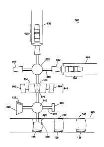
[0034] FIG. 7 illustrates a schematic view of an assembly system 600 for
wrapping the outer
wrapper 300 about the inner cup 200 to form the double-walled container 100.
First, a web 605
carrying a plurality of outer wrappers 300 enters the assembly system 600. The
outer wrapper
300 are illustrated herein as having already been provided with the adhesive
125. It will also be
understood that the outer wrappers 300 on the web 605 might not yet include
the adhesive 125,
and that the adhesive 125 will rather be applied to the outer wrapper 300 at a
later point during
the wrapping process.
-8-
CA 3053066 2019-08-26
[0035] A first rotating spindle 610 has a plurality of extending arms 615
disposed radially
about the first rotating spindle 610. At the end of each of the extending arms
615 is a suction arm
500. As a suction arm 500 is brought into alignment with an outer wrapper 300,
the outer
wrapper 300 is transferred to the suction arm 500 from the web 605 and is held
in place on the
suction arm 500 by suction force being applied by the suction arm 500. The
suction arm 500
carrying the outer wrapper 300 is then rotated about the rotating spindle 610
until it is brought
into alignment with the wrapping station 640. The suction arm 500 is also
movable up/down
relative to the outer wrapper 300. The wrapping station 640 includes the
wrapping arms 560 and
the press arm 570, with the wrapping arms 560 and the press arm 570 occupying
the start
position when the outer wrapper 300 is indexed into place in the wrapping
station 640.
[0036] Before wrapping of the outer wrapper 300 can proceed, an inner cup
200 is provided
to the wrapping station 640. A second rotating spindle 625 is provided that
can carry the inner
cups 200. The second rotating spindle 625 has a plurality of extending arms
620 disposed
radially about the second rotating spindle 625. At the end of each of the
extending arms 620 is a
mandrel 550. The mandrel 550 can be provided with air channels (not shown)
that allow the
mandrel 550 to provide suction force to hold an inner cup 200 about the
mandrel 550. A supply
tube 645 can contain a stack 650 of inner cups 200. When a mandrel 550 lines
up with the open
end of the supply tube 645 and applies suction, an inner cup 200 can be sucked
out or blown out
of the supply tube 645 and onto the mandrel 550, then held on the mandrel 550
by suction. The
mandrel 550 is then rotated by the second rotating spindle 625 to index an
inner cup 200 into
position within the wrapping station 640. At the wrapping station 640, the
outer wrapper 300 is
wrapped about the inner cup 200 to form the double-walled container 100 as
described in FIGS.
3-6.
[0037] When formation of the double-walled container 100 at the wrapping
station 640 has
been completed, the second rotating spindle 625 indexes the mandrel 550
carrying the double-
walled container 100 out of the wrapping station. The double-walled container
100 can then be
brought into alignment with a stacking tube 630. The stacking tube 630 can be
provided to
contain a stack 635 of double-walled containers 100. When the mandrel 550
carrying a double-
walled container 100 lines up with the open end of the stacking tube 630, the
application of
-9-
CA 3053066 2019-08-26
suction to the double-walled container 100 by the mandrel 550 is ceased. The
double-walled
container can then be taken up into the stacking tube 630, either by the
application of suction
from the stacking tube 630, by being blown off the mandrel 550 by positive air
pressure applied
by the mandrel 550, or a combination thereof.
[0038] While the outer wrapper 300 and the inner cup 200 have been
described herein as
being held in the spaced condition to one another by the adhesive 120 that is
applied to the inner
cup 200 prior to the wrapping of the outer wrapper 300 about the inner cup
200, it will also be
understood that a non-adhesive spacer could be used instead of or in addition
to the adhesive 120
applied to the inner cup 200. The spacer will maintain the outer wrapper 300
and the inner cup
200 in the spaced condition to one another regardless of whether or not the
spacer has adhesive
properties. The spacer can comprise, by way of non-limiting example, at least
one of an
adhesive, a bead, a strip of foam or other material, or a structural member
protruding into the
cavity 130 from at least one of the inner cup 200 or the outer wrapper 300. A
spacer with no
adhesive properties would still result in a double-walled container 100 with
the intended function
and properties as the outer wrapper 300 and the inner cup 200 would be
maintained in the spaced
condition from one another, and the outer wrapper 300 would still be held in a
fully wrapped
condition about the inner cup 200 by way of the adhesive that is provided to
at least one of the
opposing ends 315, 320 of the outer wrapper 300 prior to wrapping of the outer
wrapper 300
about the inner cup 200 to form the overlapped portion 580.
[0039] The presence of the spacer allows the outer wrapper 300 and the
inner cup 200 to be
maintained in the spaced condition from one another, even as the outer wrapper
300 is
mechanically wrapped about the inner cup 200. In methods of forming a double-
walled container
in which the outer wrapper is pre-formed into a sleeve and then slid over the
inner cup,
maintaining the spaced condition of the inner cup and the outer wrapper does
not pose the same
manufacturing challenge as the two components are already sized and formed to
fit in the spaced
condition from one another. However, such a method of assembly can result in
smearing of the
adhesive between the inner cup and the outer wrapper, compromising the cavity
and potentially
resulting in deformations that could be unpleasant to the consumer. The
wrapping method of the
disclosure solves the issue of providing a method for forming a double-walled
container in which -
-10-
CA 3053066 2019-08-26
the outer wrapper can be wrapped about the inner cup, rather than slid over
the inner cup, to
maintain the integrity of the adhesive pattern, as well as ensuring that the
inner cup and the outer
wrapper are maintained in the spaced condition through the assembly process to
ensure the
cavity is properly defined at all points.
[0040] Referring now to FIG. 8, a suction arm 500 that can be used in the
assembly system
600 to make the double-walled container 100 according to an embodiment of the
disclosure is
illustrated. The suction arm 500 can include a base portion 505 that is
generally stationary in
relation to the extending arm 615 and can be provided in a substantially
horizontal orientation.
The base portion 505 can be operably coupled to a suction source (not shown)
via a pressure
opening 510. The suction arm 500 can further include an angled portion 515.
The angled portion
515 is mechanically coupled to the base portion 505 and can be provided at an
angle relative to
the base portion 505. It is further contemplated that the angled portion 515
can be adjustable
relative to the base portion 505 such that the angle of the angled portion 515
can be adjusted to
accommodate the pitch of the container 100 to be assembled. In an exemplary
embodiment, the
angle of the angled portion 515 will be adjusted such that it corresponds to
the angle of the inner
wall 210 of the inner cup 200. At least one suction nozzle 520 can be provided
extending from
an upper surface 525 of the angled portion 515. The suction nozzles 520 can
selectively provide
suction or negative pressure to hold in place a blank or outer wrapper 300
that is applied to the
angled portion 515.
[0041] Referring now to FIG. 9, a side cross-sectional view of the suction
arm 500 of FIG. 8
is shown. In this view, it can be better seen that the base portion 505 of the
suction arm 500 can
define a suction channel 530. The suction channel 530 can include suction
branches 535. In an
exemplary embodiment, the number of suction branches 535 is equal to the
number of suction
nozzles 520 that are provided on the angled portion 515. The suction branches
535 extend
upwardly into the suction nozzles 520 to provide a suction force to the
suction nozzles 520.
[0042] Referring now to FIG. 10, a suction arm 700 that can be used in the
assembly system
600 to make the double-walled container 100 according to another embodiment of
the disclosure
is illustrated. The suction arm 700 is similar to the suction arm 500 in that
the suction arm 700
can include a base portion 705 that is generally stationary in relation to the
extending arm 615
-11-
CA 3053066 2019-08-26
and can be provided in a substantially horizontal orientation. However, it
will be understood that
a substantially horizontal orientation is not limiting, and that the base
portion 705 can be
provided at any suitable angle relative to the horizontal. The base portion
705 can be operably
coupled to a suction source (not shown) via a suction outlet 710. The suction
arm 700 can also be
moveable and configured to couple to the suction source.
[0043] The suction arm 700 can further include an angled portion 715. The
angled portion
715 is mechanically coupled to the base portion 705 and can be selectively
provided at an angle
relative to the base portion 705. It is further contemplated that the angled
portion 715 can be
adjustable in angle relative to the base portion 705 such that the angle of
the angled portion 715
relative to the base portion 705 can be adjusted to accommodate the pitch of
the container 100 to
be assembled. In an exemplary embodiment, the angle of the angled portion 715
can be adjusted
such that it corresponds to the angle of the inner wall 210 of the inner cup
200.
[0044] While the angled portion 515 was provided with suction nozzles 520
extending from
the upper surface 525 of the angled portion 515, it is contemplated that the
angled portion 715
can define a suction surface 725. The suction surface 725 can be provided with
a plurality of
suction openings 720 that are fluidly coupled to the suction source. The
suction openings 720 can
be provided within the suction surface 725 in any suitable pattern. In an
exemplary embodiment,
the suction openings 720 can be arranged in rows on the suction surface 725
and can be
distributed evenly throughout the suction surface 725. However, it will be
understood that the
arrangement of the suction openings 720 on the suction surface 725 is not
limiting.
[0045] The suction surface 725 can further comprise a sealing edge 740 that
extends about
the periphery of the suction surface 725 and circumscribes at least a portion
of the suction
surface 725. In an exemplary embodiment, the sealing edge 740 is formed from a
flexible
material such that the sealing edge 740 can conform to the outer wrapper 300
as the outer
wrapper 300 is wrapped upwardly around the inner cup 200. The sealing edge 740
can form a
continuous perimeter about the periphery of the suction surface 725 such that
an airtight suction
seal can be formed between the outer wrapper 300 and the sealing edge 740. In
an exemplary
embodiment, the sealing edge 740 is substantially flush with the suction
surface 725, such that
the sealing edge 740 minimally increases the height of the suction surface
725.
-12-
CA 3053066 2019-08-26
[0046] FIG. 11 illustrates a cross-sectional view of the angled portion 715
in which the
sealing edge 740 is in an unflexed position. The suction surface 725 can be
provided as a curved
suction surface 725, such that the left and right peripheral edges where the
sealing edge 740 is
positioned are higher than the center of the suction surface 725. The degree
of curvature of the
suction surface 725 can be any suitable curvature. In an exemplary embodiment,
the degree of
curvature of the suction surface 725 will be the same as the desired degree of
curvature of the
outer wrapper 300 about the inner cup 200 such that the inner cup 200 and
outer wrapper 300 can
rest complementary to the suction surface 725. It will be understood that the
degree of curvature
of the suction surface 725 can also be provided as flatter than or shallower
than the desired
degree of curvature of the outer wrapper 300 about the inner cup 200. Further,
the degree of
curvature of the suction surface 725 can be related to the radius of the inner
cup 200 or the
double-walled container 100 being wrapped. Each of the suction openings 720
can be fluidly
coupled to the suction outlet 710 via suction channels 745 defined by the
angled portion 715.
[0047] The sealing edge 740 can be thought of as comprising a sealing body
750 and a
sealing flange 755. The sealing body 750 can extend downwardly relative to the
suction surface
725 for attachment to the angled portion 715, while the sealing flange 755
extends outwardly
from the sealing body 750, away from the center of the suction surface 725. In
an exemplary
embodiment, the sealing flange 755 can narrow or taper away from the Center of
the suction
surface 725. It will be understood that the sealing body 750 may be
substantially stationary while
the sealing flange 755 can flex upwardly and downwardly relative to the
suction surface 725.
[0048] FIG. 12 illustrates a cross-sectional view of the angled portion 715
in which the
sealing edge 740 is in a flexed position. In the flexed position, the sealing
flange 755 flexes
upwardly away from the suction surface 725. This occurs as the outer wrapper
300 is wrapped
upwardly around the inner cup 200 due to suction coupling between the sealing
flange 755 and
the outer wrapper 300.
[0049] FIG. 13 illustrates a cross-sectional view of the angled portion 715
with the sealing
edge 740 in the unflexed position according to another embodiment of the
invention. In this
embodiment, the structure of the angled portion 715 and the sealing edge 740
is the same as that
shown in FIG. 11, except that the suction surface 725 and the sealing flange
755 are flat. Rather
-13-
CA 3053066 2019-08-26
than having a curvature as in the embodiment of FIG. 11, the suction surface
725 and the sealing
flange 755 are substantially horizontal and without curvature in the unflexed
position.
[0050] Turning now to the operation of the suction surface 725, when the
outer wrapper 300
is to be wrapped upwardly around the inner cup 200, the outer wrapper 300 is
indexed into place
onto the angled portion 715. When the outer wrapper 300 is in place on the
angled portion 715,
the outer wrapper 300 contacts the sealing flange 755 about the entire
perimeter of the sealing
flange 755. Suction or negative pressure is applied by the suction source via
the suction outlet
710 and the suction channels 745 to the suction openings 720. The force of the
suction from the
suction openings 720 against the outer wrapper 300 causes a suction seal to be
formed between
the outer wrapper 300 and the sealing flange 755. In an exemplary embodiment,
the suction seal
can be an airtight seal, though it will be understood that the suction seal
need not be perfectly
airtight, so long as the suction is sufficient to hold the outer wrapper 300
in place as the outer
wrapper 300 is wrapped upwardly about the inner cup 200. The suction and the
seal between the
outer wrapper 300 and the sealing flange 755 are maintained as wrapping of the
outer wrapper
300 proceeds. As the outer wrapper 300 is wrapped upwardly about the inner cup
200, the
airtight seal and the suction cause the sealing flange 755 to stay in contact
with the outer wrapper
300 and to move with the outer wrapper 300 from the unflexed position to the
flexed position,
such that the sealing flange 755 moves from the unflexed position to conform
to the shape of the
outer wrapper 300 as it is wrapped about the inner cup 200. The sealing flange
755 can maintain
the flexed position against the outer wrapper 300 until the overlapped portion
580 has been
adhered. Once the formation of the double-walled container 100 at the wrapping
station 640 has
been completed, the suction can cease and the double-walled container 100 is
removed from the
angled portion 715.
[0051] The embodiments of the disclosure described herein provide a method
of making a
double-walled cup or container, which can be formed of paper, which can be
used to address
challenges associated with forming an insulating cup by ensuring that the
inner cup and the outer
wrapper are maintained in a spaced condition from one another for optimal
insulative
performance of the cavity. If the spacer or adhesive were not present or were
to become
compressed, the width of the cavity between the inner cup and the outer
wrapper would be
-14-
CA 3053066 2019-08-26
decreased, which would negatively impact the insulative performance of the
double-walled cup.
The methods described herein allow for the manufacture of a double-walled cup
in a way in
which the spaced condition is maintained at a desired width with decreased
opportunity for the
spacer or adhesive to become undesirably compressed about the circumference of
the cup. The
provision of the sealing flange with its flexibility and ability to conform to
the shape of the
double-walled cup or container allowed for a better seal that can be
maintained even as the outer
wrapper is wrapped about the inner cup. By maintaining the suction and the
airtight seal between
the sealing flange and the outer wrapper throughout the wrapping step and
until the overlapped
portion has been fully adhered, it can be ensured that the outer wrapper does
not shift or move
out of place on the angled surface. This allows for consistent positioning of
the outer wrapper
during the wrapping process, resulting in the formation of consistent and
correct double-walled
containers.
[0052] To the extent not already described, the different features and
structures of the various
embodiments of the disclosure may be used in combination with each other as
desired. That one
feature may not be illustrated in all of the embodiments is not meant to be
construed that it
cannot be, but is done for brevity of description. Thus, the various features
of the different
embodiments may be mixed and matched as desired to form new embodiments,
whether or not
the new embodiments are expressly described.
[0053] While the disclosure has been specifically described in connection
with certain
specific embodiments thereof, it is to be understood that this is by way of
illustration and not of
limitation. Reasonable variation and modification are possible within the
scope of the forgoing
disclosure and drawings without departing from the spirit of the disclosure
which is defined in
the appended claims.
-15-
CA 3053066 2019-08-26