Note: Descriptions are shown in the official language in which they were submitted.
25.0470A-US-CI P
TORQUE-BALANCED, GAS-SEALED WIRELINE CABLES
CROSS-REFERENCE TO RELATED APPLICATIONS
[0001] This
Application is a continuation-in-part application of co-pending US
Patent Application Serial No. 15/214703, entitled: "Torque-Balanced, Gas-
Sealed
Wireline Cables", filed on July 20, 2016, which is a continuation application
of then
co-pending US Patent Application Serial No. 12/425439, entitled: "Torque-
Balanced,
Gas-Sealed Wireline Cables", filed on April 17, 2009, and granted as US Patent
No.:
9,412,492, this Application is also a continuation-in-part application of co-
pending
U.S. Patent Application Serial No. 15/617270, filed June 9, 2017, entitled
"Wireline
Cable For Use With Downhole Tractor Assemblies" which is a continuation of
then
co-pending U.S. Patent Application Serial No. 14/705,094, filed May 06, 2015,
now
U.S. Patent No. 9,677,359, which is a continuation of U.S. Patent Application
Serial
No. 13/497,142, filed May 9, 2012 now granted as US Patent 9,027,657, which is
a
371 of International Application No. PCT/US2010/049783, filed September 22,
2010,
which claims benefit of United States Provisional Patent Application Serial
No.
61/277,219, filed September 22, 2009, furthermore this application is a
continuation-
in-part of co-pending U.S. Patent Application U.S. Patent Application Serial
No.
15/180789, entitled: " Cable or Cable Portion with a Stop Layer", which as a
continuation application of then co-pending U.S Patent Application Serial No.
13/702919, entitled: "Cable Or Cable Portion With A Stop Layer" now U.S.
Patent
No. 9,368,260, which is a 371 of International Application No.
PCT/U52011/039879,
filed June 9, 2011, which claims benefit of United States Provisional Patent
Application Serial No. 61/397,255, filed June 9, 2010; the entirety of all of
above are
incorporated herein by reference.
1
CA 3053130 2019-08-27
= 25 .0470A-US-C I P
FIELD
[0002]
Embodiments of the present disclosure generally relate to downhole
cables.
BACKGROUND
[0001] The statements in this section merely provide background information
related
to the present disclosure and may not constitute prior art.
[0002] The present disclosure relates generally to oilfield cables and, in
particular, to
wireline cables, and methods of making and using such cables.
[0003] Several common problems encountered with wireline cables used in
oilfield
operations are related to armor wire strength members. Armor wire is typically
constructed of cold-drawn plow ferritic steel coated with a zinc coating for
corrosion
protection. These armor wires provide the strength needed to raise and lower
the
weight of the cable and tool string and protect the cable core from impact and
abrasion damage. Typical wireline cable designs consist of a cable core of one
or
more insulated conductors (packed in an interstitial filler in the case of
multiple
conductors) wrapped in cabling tape followed by the application of two armor
wire
layers. The armor wire layers are applied counterhelically to one another in
an effort
to minimize torque imbalance between the layers. In an effort to provide
additional
protection against impact, cut through, and abrasion damage, larger-diameter
armor
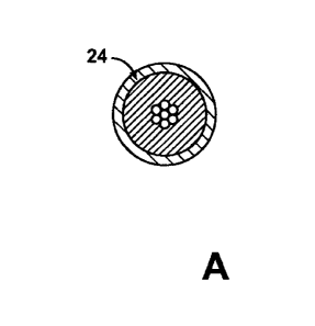
wires are typically placed in the outer layer. Due to shortcomings in these
designs,
torque imbalance between the armor wire layers continues to be an issue,
resulting
in cable stretch, cable core deformation and significant reductions in cable
strength.
[0004] In pressurized wells, gas can infiltrate through gaps between the armor
wires
and travel along spaces existing between the inner armor wire layer and the
cable
core. Grease-filled pipes at the well surface provide a seal at the well
surface. As the
wireline cable passes through these pipes, pressurized gas can travel through
the
spaces among armor wires and the cable core. When the cable then passes over
and bends over a sheave, the gas is released, resulting in an explosion and
fire
hazard.
[0005] In typical wireline cable designs, such as a wireline cable 10 shown in
Fig. 1,
outer armor wires 11 were sized larger than inner armor wires 12 in an effort
to
provide greater protection against impact, cut-through, and abrasion damage.
One
2
CA 3053130 2019-08-27
. .
25.0470A-US-CI P
,
unintended effect of this design strategy is to increase torque imbalance. In
those
designs, the outer armor wires 11 carry roughly 60% of the load placed on the
cable.
This causes the outer armor wires 11 to straighten slightly when the cable is
under
tension, which in turn causes the cable core 13 to stretch and the inner armor
wires
12 to be wound more tightly around the cable core. The outer armor wires 11
and
inner armor wires 12 may come into point-to-point contact which wears away the
protective zinc layer leading to premature corrosion. The cable core 13 can
also be
damaged as it deforms into the interstitial spaces between the inner armor
wires 12.
Additionally, because the outer armor wires 11 are carrying the bulk of the
load, they
are more susceptible to breaking if damaged, thereby largely negating any
benefits of
placing the larger armor wires in the outer layer.
[0006] Under tension, the inner and outer armor wires (which are applied at
opposite
lay angles) tend to rotate in opposite directions as shown by arrows 14 and 15
respectively as shown in Fig. 1. Because the larger outer armor wires 11 are
dominant, the outer armor wires tend to open, while the inner armor wires 12
tighten,
causing torque imbalance problems. To create a torque-balanced cable, the
inner
armor wires would have to be somewhat larger than the outer armor wires. This
configuration has been avoided in standard wireline cables in the belief that
the
smaller outer wires would quickly fail due to abrasion and exposure to
corrosive
fluids. Therefore, larger armor wires have been placed at the outside of the
wireline
cable, which increases the likelihood and severity of torque imbalance.
[0007] Torque for a layer of armor wire can be described in the following
equation.
[0008] Torque = % T x PD x sin 2a
[0009] Where: T = Tension along the direction of the cable; PD = Pitch
diameter of
the armor wires; and a = Lay angle of the wires.
[0010] Pitch diameter (the diameter at which the armor wires are applied
around the
cable core or the previous armor wire layer) has a direct effect on the amount
of
torque carried by that armor wire layer. When layers of armor wire constrict
due to
cable stretch, the diameter of each layer is reduced numerically the same.
Because
this reduction in diameter is a greater percentage for the inner layer of
armor wires
12, this has a net effect of shifting a greater amount of the torque to the
outer layer of
armor wires 11.
3
CA 3053130 2019-08-27
. .
25.0470A-US-CIP
i
[0011] In high-pressure wells, the wireline 10 is run through one or several
lengths of
piping 16 packed with grease to seal the gas pressure in the well while
allowing the
wireline to travel in and out of the well (see Fig. 2). Armor wire layers have
unfilled
annular gaps between the armor wire layers and the cable core. Under well
conditions, well debris and the grease used in the risers can form a seal over
the
armor wires, allowing pressurized gas to travel along the cable core beneath
the
armor wires. Pressurized gas from the well can infiltrate through spaces
between the
armor wires and travel upward along the gaps between the armor wires and the
cable core upward toward lower pressure. Given cable tension and the sealing
effects of grease from the risers and downhole debris coating the armor wire
layers,
this gas tends to be held in place as the wireline travels through the grease-
packed
risers. As the wireline 10 bends when passing over the upper sheave 17
(located
above the risers), the armor wires tend to spread apart slightly and the
pressurized
gas 18 is released. This released gas 18 becomes an explosion hazard (see Fig.
3).
[0012] It is desirable, therefore, to provide a cable that overcomes the
problems
encountered with wireline cable designs.
[0013] The disclosed designs minimize the problems described above by:
[0014] Placing layers of soft polymer between the inner armor wires and the
cable
core and between the inner and outer armor wire layers; and
[0015] Using larger-diameter armor wires for the inner layer than for the
outer layer.
[0016] The polymeric layers provide several benefits, including:
[0017] Eliminating the space along the cable core and the first layer of armor
along
which pressurized gas might travel to escape the well;
[0018] Eliminating the space into which the cable core might creep and deform
against the inner armor wires;
[0019] Cushioning contact points between the inner and outer armor wires to
minimize damage from armor wires rubbing against each other;
[0020] Filling space into which the inner armor wire might otherwise be
compressed,
thereby minimizing cable stretch; and
4
CA 3053130 2019-08-27
. .
25.0470A-US-ClP
[0021] Filling space into which the inner armor wire might otherwise be
compressed,
thereby minimizing the above-described effect of shifting torque to the outer
armor
wire layer when the diameters of both the inner and outer armor wire layers
are
decreased by the same amount.
[0022] Torque balance is achieved between the inner and outer armor wire
layers by
placing larger wires in the inner layer. As explained below, this allows the
majority of
the load to be carried by the inner armor wires. While in traditional armor
wire
configurations, the outer wires ended up carrying approximately 60 percent of
the
load and the inner wires approximately 40 percent. By placing the larger armor
wires
in the inner layer, the proportions of load can be more or less reversed,
depending on
individual cable design specifications.
[0023] The designs place soft thermoplastic polymer layers over the cable core
and
between the inner and outer armor wire layers and reconfigure the sizes of
armor
wires used such that larger armor wires are placed in the inner layer. As an
option,
these designs may utilize solid armor wires in the inner layer and stranded
armor
wires in the outer layer. These design changes result in a more truly torque-
balanced
cable that is sealed against intrusion and travel of pressurized gas. These
designs
may also have an outer layer of polymer to create a better seal at the well
surface.
SUMMARY
[0024] A smooth torque balanced cable. The smooth torque balanced cable
includes
an electrically conductive cable core for transmitting electrical power. A
first polymer
surrounds the cable core. An inner layer of a plurality of first armor wires
surrounds
the cable core, and the first armor wires are at least in partial contact with
the first
polymer and at least partial contact with a second polymer disposed opposite
the first
polymer. An outer layer of a plurality of second armor wires surrounds the
inner layer.
The second armor wires have a stranded configuration. Interstitial spaces
between
the second armor wires are at least partially filled with a third polymer, and
the outer
layer of a plurality of second armor wires is at least partially covered by
the third
polymer. The third polymer is ethylene-tetrafluoroethylene. The coverage of
the outer
layer of armor wires over the inner layer of armor wires is less than or
approximately
equal to 88 percent. The second polymer separates the plurality of first armor
wires
from the plurality of second armor wires.
CA 3053130 2019-08-27
25.0470A-US-C I P
=
[0025] A method of conveying torque balanced cable into a wellbore includes
connecting a cable to downhole equipment. The cable includes an electrical
conductive core and at least a smooth outer jacket. The method also includes
passing the cable and downhole equipment through pressure control equipment,
wherein a seal is formed between the smooth outer jacket and a rubber pack-
off, and
the running of the cable into the wellbore is done without the use of grease
in the
pressure control equipment, and wherein the torque in the cable is balanced.
[0026] A method of forming a cable, the method includes providing an
electrically
conductive cable core for transmitting electrical power. The method also
includes
surrounding the cable core with a first polymer material and providing a
plurality of
first armor wires and winding the first armor wires around the first polymer
to form an
inner layer of armor wires imbedded in the first polymer. The method also
includes
providing a second polymer about the inner layer of first armor wires. The
method
can also include providing a plurality of second armor wires and winding the
second
armor wires around the inner layer to form an outer layer of armor wires. The
coverage of the outer layer of armor wires over the inner layer of armor wires
is less
than or approximately equal to 88 percent, and wherein the second polymer
separates the plurality of first armor wires from the plurality of second
armor wires.
BRIEF DESCRIPTION OF THE DRAWINGS
[0027] These and other features and advantages of the present invention will
be
better understood by reference to the following detailed description when
considered
in conjunction with the accompanying drawings wherein:
[0028] Fig. 1 is a radial cross-sectional view of a prior art wireline cable;
[0029] Fig. 2 is a schematic cross-sectional view of the prior art wireline
cable shown
in Fig. 1 in use;
[0030] Fig. 3 is an enlarged view of the prior art wireline cable and the
upper sheave
shown in Fig. 2;
[0031] Figs. 4A through 4D are radial cross-sectional views of a first
embodiment
wireline mono cable;
6
CA 3053130 2019-08-27
25.0470A-US-CIP
[0032] Figs. 5A through 5D are radial cross-sectional views of a second
embodiment
wireline coaxial cable;
[0033] Figs. 6A through 6D are radial cross-sectional views of a third
embodiment
wireline hepta cable;
[0034] Figs. 7A through 7D are radial cross-sectional views of a fourth
embodiment
wireline hepta cable;
[0035] Figs. 8A through 8D are radial cross-sectional views of a fifth
embodiment
wireline hepta cable;
[0036] Figs. 9A through 9D are radial cross-sectional views of a sixth
embodiment
wireline hepta cable;
[0037] Fig. 10 is a radial cross-sectional view of a seventh embodiment
wireline
cable;
[0038] Fig. 11 is a radial cross-sectional view of an eighth embodiment
wireline
cable; and
[0039] Fig. 12 is a schematic representation of a manufacturing line for
constructing
wireline cable.
[0040] FIGs. 13-25 are a radial cross-sectional views, respectively, of
embodiments
of a wireline cable.
DETAILED DESCRIPTION
[0041] Illustrative embodiments of the invention are described below. In the
interest
of clarity, not all features of an actual implementation are described in this
specification. It will of course be appreciated that in the development of any
such
actual embodiment, numerous implementation- specific decisions must be made to
achieve the developer's specific goals, such as compliance with system related
and
business related constraints, which will vary from one implementation to
another.
Moreover, it will be appreciated that such a development effort might be
complex and
time consuming but would nevertheless be a routine undertaking for those of
ordinary
skill in the art having the benefit of this disclosure.
[0042] The present invention relates to a wireline cable that utilizes soft
polymers as
interstitial fillers beneath and between the armor wire layers, which soft
polymers
7
CA 3053130 2019-08-27
25.0470A-US-CIP
=
may be any suitable material, including but not limited to the following:
polyolefin or
olefin-base elastomer (such as Engage/0, Infuse , etc.); thermoplastic
vulcanizates
(TPVs) such as Santoprene and Super TPVs and fluoro TPV (F-TPV); silicone
rubber; acrylate rubber; soft engineering plastics (such as soft modified
polypropylene sulfide (PPS] or modified Poly-ether-ether-ketone [PEEK]); soft
fluoropolymer (such as high-melt flow ETFE (ethylene-tetrafluoroethylene)
fluoropolymer; fluoroelastomer (such as DAI-ELTm manufactured by Daikin); and
thermoplastic fluoropolymers.
[0043] The above polymers can be also used with various additives to meet the
mechanical requirement.
[0044] Armor wire strength members may be any suitable material typically used
for
armor wires, such as: galvanized improved plow steel (with a variety of
strength
ratings); high-carbon steel; and 27-7 Molybdenum. These may be used as solid
armors or stranded members.
[0045] Low-temperature polymers may be used for the polymeric jacketing layers
to
enable the armoring process to be stopped without damaging the cable core.
This
strategy, as discussed below, requires that the "low-temperature" polymers
have
process temperatures 25 F to 50 F below those used in the cable core. Possible
jacketing materials include: polyolefin-base and acrylate-base polymers with
process
temperatures in ranging from 300 F to 450 F; and fluoropolymer with lower
melting
point.
[0046] The core polymers are chosen to have higher melting point than the
processing temperature of the polymers selected to fill the space between the
core
and inner wire, and also the space between inner armor and outer armor wires.
This
allows combining the armoring and extrusion process at the same time to stop
the
armoring process for troubleshooting when needed with no concerns of getting
melted and thermally degraded core polymers in the extrusion crosshead.
[0047] The key to achieving torque balance between the inner and outer armor
wire
layers is to size the inner armor wires appropriately to carry their share of
the load.
Given the likelihood that some minimal amount of stretch may occur, these
designs
begin with the inner armor wires carrying slightly approximately 60 per cent
of the
load. Any minimal stretch that may occur (which tends to shift load to the
outer armor
8
CA 3053130 2019-08-27
25.0470A-US-CIP
wires) will therefore only tend to slightly improve torque balance between the
armor
wire layers.
[0048] In a torque-balanced cable: Torque; = Torque.
[0049] Where: Torque; = Torque of the inner armor wires; and Torque, = Torque
of
the outer armor wires.
[0050] Torque for a layer of armor wires in a wireline cable can be measured
by
applying the following equation:
[0051] Torque = 1/4 T x PD x sin 2a
[0052] Where: T = Tension along the direction of the cable; PD = Pitch
diameter of
the armor wires; and a = Lay angle of the wires.
[0053] The primary variable to be adjusted in balancing torque values for
armor
wires applied at different circumferences is the diameter of the wires. The
lay angles
of the inner and outer armor wires are typically roughly the same, but may be
adjusted slightly to optimize torque values for different diameter wires.
Because the
inner layer of wires has a smaller circumference, the most effective strategy
for
achieving torque balance is for their individual diameters to be larger than
those in
the outer layer. Several sample embodiments of torque-balanced, gas-blocking
wireline cable designs are described below that apply these principles. In no
way do
these examples describe all of the possible configurations that can be
achieved by
applying these basic principles.
[0054] A first embodiment is a 0.26 0.02 inch diameter mono/coaxial/triad or
other
configuration wireline cable with torque balance and gas-blocking design
(Figs. 4A
through 4D) -
[0055] For a mono/coaxial/triad or any other configuration wireline cable 20
with a
core diameter of 0.10-0.15 inch and a completed diameter of 0.26 0.02 inch,
torque
balance could be achieved with inner armor wires 21 of 0.035-0.055 inch
diameter
and outer armor wires 22 with diameters of 0.020-0.035 inch. The gas blocking
is
achieved by placing a layer 23 of soft polymer (Fig. 4B) over the cable core
24 (Fig.
4A) before the inner armor wires 21 are cabled over the core (Fig. 4C). The
inner
armor wires 21 imbed partially into the soft polymer layer 23 such that no
gaps are
left between the inner armor wires and the cable core. A second layer 25 of
soft
polymer (Fig. 4C) is optionally extruded over the inner armor wires 21 before
the
9
CA 3053130 2019-08-27
. .
25.0470A-US-CIP
'
outer armor wires 22 are applied to the cable (Fig. 4D). The second layer 25
of soft
polymer fills any spaces between the inner and outer armor wires layers and
prevents pressurized gas from infiltrating between the armor wires. By
eliminating
space for the inner armor wires to compress into the cable core 24, the cable
20 also
significantly minimizes cable stretching which helps to further protect the
cable
against developing torque imbalance in the field. For the values given for
this cable,
the inner armor wire layer 21 will carry approximately 60% of the load.
[0056] A second embodiment is a 0.32 0.02 inch diameter mono/coaxial/hepta or
other configuration wireline cable with torque balance and gas-blocking design
(Figs.
5A through 5D) ¨
[0057] For a mono/coaxial/hepta or any other configuration wireline cable 30
with a
core diameter of 0.12-0.2 inch and a completed diameter of 0.32 0.02 inch,
torque
balance could be achieved with inner armor wires 31 of 0.04-0.06 inch diameter
and
outer wires 32 with diameters of 0.02-0.04 inch. The gas blocking is achieved
by
placing a layer 33 of soft polymer (Fig. 5B) over the cable core 34 (Fig. 5A)
before
the inner armor wires are cabled over the core. The inner armor wires 31 imbed
partially into the soft polymer layer 33 (Fig. 5C) such that no gaps are left
between
the inner armor wires and the cable core 34. A second layer 35 of soft polymer
(Fig.
5D) is optionally extruded over the inner armor wires 31 before the outer
armor wires
32 are applied to the cable 30. The second layer 35 of soft polymer fills any
spaces
between the inner and outer armor wires layers and prevents pressurized gas
from
infiltrating between the armor wires. By eliminating space for the inner armor
wires to
compress into the cable core 34, the cable 30 also significantly minimizes
cable
stretching which helps to further protect the cable against developing torque
imbalance in the field. For the values given for this cable, the inner armor
wire layer
31 will carry approximately 60% of the load.
[0058] A third embodiment is a 0.38 0.02 inch diameter hepta/triad/quad or
any
other configuration wireline cable with torque balance and gas blocking (Figs.
6A
through 6D) ¨
[0059] For a hepta/triad/quad or any other wireline cable 40 configuration
with a core
diameter of 0.24-0.29 inch and a completed diameter of 0.38 0.02 inch, torque
balance could be achieved with inner armor wires 41 of 0.04-0.06 inch diameter
and
outer wires 42 with diameters of 0.025-0.045 inch. The gas blocking is
achieved by
placing a layer 43 of soft polymer (Fig, 6B) over the cable core 44 (Fig. 6A)
before
CA 3053130 2019-08-27
25.0470A-US-CIP
the inner armor wires 41 are cabled over the core. The inner armor wires 41
imbed
partially into the soft polymer (Fig. 6C) such that no gaps are left between
the inner
armor wires and the cable core 44. A second layer 45 of soft polymer (Fig. 6D)
is
optionally extruded over the inner armor wires 41 before the outer armor wires
42 are
applied to the cable 40. The second layer 45 of soft polymer fills any spaces
between
the inner and outer armor wires layers and prevents pressurized gas from
infiltrating
between the armor wires. By eliminating space for the inner armor wires 41 to
compress into the cable core 44, the cable 40 also significantly minimizes
cable
stretching which helps to further protect the cable against developing torque
imbalance in the field. For the values given for this cable, the inner armor
wire layer
will carry approximately 60% of the load.
[0060] A fourth embodiment is a 0.42 0.02 inch diameter hepta/triad/quad or
any
other configuration wireline cable with torque balance and gas blocking (Figs.
7A
through 7D) -
[0061] For a hepta/triad/quad or any other wireline cable 50 configuration
with a core
diameter of 0.25-0.30 inch and a completed diameter of 0.42 0.02 inch, torque
balance could be achieved with inner armor wires 51 of 0.04-0.06 inch diameter
and
outer armor wires 52 with diameters of 0.025-0.045 inch. The gas blocking is
achieved by placing a layer 53 of soft polymer (Fig. 7B) over the cable core
54 (Fig.
7A) before the inner armor wires 51 are cabled over the core (Fig. 7C). The
inner
armor wires 51 imbed partially into the soft polymer layer 53 such that no
gaps are
left between the inner armor wires and the cable core 54. A second layer 55 of
soft
polymer (Fig. 7D) is optionally extruded over the inner armor wires 51 before
the
outer armor wires 52 are applied to the cable 50. The second layer 55 of soft
polymer
fills any spaces between the inner and outer armor wires layers and prevents
pressurized gas from infiltrating between the armor wires. By eliminating
space for
the inner armor wires 51 to compress into the cable core 54, the cable 50 also
significantly minimizes cable stretching which helps to further protect the
cable
against developing torque imbalance in the field. For the values given for
this cable,
the inner armor wire layer will carry approximately 60% of the load.
[0062] A fifth embodiment is a 0.48 0.02 inch diameter hepta/triad/quad or
any
other configuration wireline cable with torque balance and gas blocking (Figs.
8A
through 8D) -
11
CA 3053130 2019-08-27
. .
25.0470A-US-CIP
[0063] For a hepta/triad/quad or any other wireline cable 60 configuration
with a core
diameter of 0.20-0.35 inch and a completed diameter of 0.48 0.02 inch, torque
balance could be achieved with inner armor wires 61 of 0.05-0.07 inch diameter
and
outer armor wires 62 with diameters of 0.03-0.05 inch. The gas blocking is
achieved
by placing a layer 63 of soft polymer (Fig. 8B) over the cable core 64 (Fig.
8A) before
the inner armor wires 61 are cabled over the core (Fig. 8C). The inner armor
wires 61
imbed partially into the soft polymer layer 63 such that no gaps are left
between the
inner armor wires and the cable core 64. A second layer 65 of soft polymer
(Fig. 8D)
is optionally extruded over the inner armor wires 61 before the outer armor
wires 62
are applied to the cable 60. The second layer 65 of soft polymer fills any
spaces
between the inner and outer armor wires layers and prevents pressurized gas
from
infiltrating between the armor wires. By eliminating space for the inner armor
wires 61
to compress into the cable core 64, the cable 60 also significantly minimizes
cable
stretching which helps to further protect the cable against developing torque
imbalance in the field. For the values given for this cable, the inner armor
wire layer
will carry approximately 60% of the load.
[0064] A sixth embodiment is a 0.52 0.02 inch diameter hepta cable with
torque-
balanced, gas-blocking design (Figs. 9A through 9D) -
[0065] For a hepta cable 70 with a core diameter of 0.25-0.40 inch and a
completed
diameter of 0.52 0.02 inch, torque balance could be achieved with inner armor
wires
71 of 0.05-0.07 inch diameter and outer armor wires 72 with diameters of 0.03-
0.05
inch. The gas blocking is achieved by placing a layer 73 of soft polymer (Fig.
9B)
over the cable core 74 (Fig. 9A) before the inner armor wires 71 are cabled
over the
core (Fig, 9C). The inner armor wires 71 imbed partially into the soft polymer
layer 73
such that no gaps are left between the inner armor wires and the cable core
74. A
second layer 75 of soft polymer (Fig. 9D) is optionally extruded over the
inner armor
wires 71 before the outer armor wires 72 are applied to the cable 70. The
second
layer 75 of soft polymer fills any spaces between the inner and outer armor
wires
layers and prevents pressurized gas from infiltrating between the armor wires.
By
eliminating space for the inner armor wires 71 to compress into the cable core
74, the
cable 70 also significantly minimizes cable stretching which helps to further
protect
the cable against developing torque imbalance in the field. For the values
given for
this cable, the inner armor wire layer will carry approximately 60% of the
load.
[0066] A seventh embodiment includes an optional stranded wire outer armoring
(Fig. 10) -
12
CA 3053130 2019-08-27
25.0470A-US-ClP
=
[0067] As an option in any of the embodiments described above, the outer layer
of
solid armor wires may be replaced with similarly sized stranded wires 81 in a
wireline
cable 80 as shown in Fig. 10. If a stranded wire is used on the outside, a
jacket 82 is
put over the top of the stranded wires 81 and bonded to the inner jacket
between the
stranded wires in order not to expose the small individual elements directly
to well
bore conditions of abrasion and cutting.
[0068] An eighth embodiment includes an outer, easily sealed polymeric jacket
(Fig.
11) -
[0069] To create torque-balanced, gas-sealed cables that are also more easily
sealed by means of a rubber pack-off instead of pumping grease through flow
tubes
at the well surface, any of the above embodiments may be provided with an
outer
polymeric jacket 91. To continue the gas-sealed capabilities to the outer
diameter of
the cable 90, this polymeric material can be bondable to the other jacket
layers. For
example (as shown in Fig. 11), an outer jacket 91 of carbon-fiber-reinforced
ETFE
(ethylene-tetrafluoroethylene) fluoropolymer may be applied over the outer
armor
wire layer 72, bonding through the gaps in the outer strength members. This
creates
a totally bonded jacketing system and with the addition of the fiber-
reinforced
polymer, also provides a more durable outer surface. For this, the polymer
that is
placed between the inner and outer armor layers needs to bond to the jacket
placed
on top of the outer armor wires 72 through the gap in the outer armor wires.
[0070] In any of the above-described embodiments, polymers for the armor-
jacketing
layers may be chosen with significantly lower process temperatures (25 F to 50
F
lower) than the melting point of polymers used in the cable core. This enables
the
armoring process to be stopped and started during armoring without the risk
that
prolonged exposure to extruding temperatures will damage the cable core. This
on-
line process is as follows with reference to a schematic representation of a
wireline
cable manufacturing line 100 shown in Fig. 12:
[0071] A cable core 101 enters the armoring process line 100 at the left in
Fig. 12.
[0072] A layer of soft polymer 102 is extruded over the cable core 101 in a
first
extrusion station 103. The soft outer polymer allows for better and more
consistent
embedding of the armor wires into the polymer. In case that the cable core 101
needs to be protected during the armoring process or harsh field operation,
dual
layers of hard and soft polymers can be co-extruded over the cable core. A
hard
13
CA 3053130 2019-08-27
25.0470A-US-CIP
polymer layer placed underneath a soft polymer layer is mechanically resistant
so
that such a layer could prevent armor wires from breaking into the cable core
through
the soft layer. Alternatively this layer could be extruded prior to the
armoring process.
[0073] An inner armor wire layer 104 is cabled helically over and embedded
into the
soft polymer 102 at a first armoring station 105. While armoring, any
electromagnetic
heat source such as infrared waves, ultrasonic waves, and microwaves may be
used
to further soften the polymers to allow the armoring line 100 to be run
faster. This
could be applied before the armor hits the core or after the armor touches the
core.
[0074] A second layer 106 of soft polymer is extruded over the embedded inner
layer
104 of armor wires at a second extrusion station 107.
[0075] An outer armor wire layer 108 is cabled (counterhelically to the inner
armor
wire layer 104) over and embedded into the soft polymer 106 at a second
armoring
station 109. While armoring, any electromagnetic heat source such as infrared
waves, ultrasonic waves, and microwaves maybe used to further soften polymers
to
allow the armoring line 100 to be run faster. This could be applied before the
armor
hits the core or after the armor touches the core.
[0076] If needed, a final layer 110 of hard polymer is extruded over the
embedded
outer armor wire layer 108 at a third extrusion station 111 to complete the
cable as
described above.
[0077] Although the on-line combined process as described is preferred to save
a
significant amount of manufacturing time, each step of the process can be
separated
for accommodation of process convenience.
[0078]
Referring to FIG. 13, there is illustrated a torque balanced cable 200 for
downhole operations according to a first embodiment of the present invention.
As
shown, the cable 200 includes a core 202 having a plurality of conductors 204.
As a
non-limiting example, each of the conductors 204 is formed from a plurality of
conductive strands 206 disposed adjacent each other with an insulator 208
disposed
therearound. As a further non-limiting example, the core 202 includes seven
distinctly insulated conductors 204 disposed in a hepta cable configuration.
However, any number of conductors 204 can be used in any configuration, as
desired. In certain embodiments an interstitial void 210 formed between
adjacent
insulators 208 is filled with a semi-conductive (or non-conductive) filler
(e.g. filler
strands, polymer insulator filler).
14
CA 3053130 2019-08-27
25.0470A-US-CIP
[0079] The core 202 is surrounded by an inner layer of armor wires 212
(e.g.
high modulus steel strength members) which is surrounded by an outer layer of
armor wires 214. The armor wires 212 and 214 may be alloy armor wires. As a
non-
limiting example the layers 212, 214 are contra helically wound with each
other. As
shown, a coverage of the circumference of the outer layer 214 over the inner
layer
212 is reduced from the 98% coverage found in conventional wireline cables to
a
percentage coverage that matches a torque created by the inner layer 212. As a
non-limiting example the coverage of the outer layer 214 over the inner layer
is
between about 60% to about 88%. The reduction in the coverage allows the cable
200 to achieve torque balance and advantageously minimizes a weight of the
cable
200. An interstitial void created in the outer layer 214 (e.g. between
adjacent ones of
the armor wires of the outer layer 214) is filled with a polymer as part of a
jacket 216.
In the embodiment shown, the jacket 216 encapsulates at least each of the
layers
212, 214. As a non-limiting example, that jacket 216 includes a substantially
smooth
outer surface 218 (i.e. exterior surface) to minimize a friction coefficient
thereof. It is
understood that various polymers and other materials can be used to form the
jacket
216. As a further non-limiting example, the smooth outer jacket 216 is bonded
from
the core 202 to the outer surface 218. In certain embodiments, the coefficient
of
friction of a material forming the jacket 216 is lower than a coefficient of
friction of a
material forming the interstices or insterstitial voids of the layers 212,
214. However,
any materials having any coefficient of friction can be used.
[0080] In operation, the cable 200 is coupled to a tractor and/or
other wellbore
service equipment in a configuration known in the art. The cable 200 is
introduced
into the wellbore, wherein a torque on the cable 200 is substantially balanced
and a
friction between the cable 200 and the wellbore is minimized by the smooth
outer
surface 218 of the jacket 216. It is understood that various tool strings,
such as the
tool string 104, can be attached or coupled to the cable 200 and the tractor,
such as
the tractor 102, to perform various well service operations known in the art
including,
but not limited to, a logging operation, a mechanical service operation, or
the like.
[0081] FIG.14 illustrates a torque balanced cable 300 for downhole
operations
according to a second embodiment of the present invention similar to the cable
200,
except as described below. As shown, the cable 300 includes a core 302, an
inner
layer of armor wires 304, an outer layer of armor wires 306, and a polymeric
jacket
308. As a non-limiting example, the jacket 308 is formed from a fiber
reinforced
polymer that encapsulates each of the layers 304, 306. As a non-limiting
example,
CA 3053130 2019-08-27
25.0470A-US-CI P
the jacket 308 includes a smooth outer surface 310 to reduce a frictional
coefficient
thereof. It is understood that various polymers and other materials can be
used to
form the jacket 308.
[0082] An outer surface of each of the layers 304, 306 includes a
suitable
metallic coating 312 or suitable polymer coating to bond to the polymeric
jacket 308.
Therefore, the polymeric jacket 308 becomes a composite in which the layers
304,
306 (e.g. high modulus steel strength members) are embedded and bonded in a
continuous matrix of polymer from the core 302 to the outer surface 310 of the
jacket
308. It is understood that the bonding of the layers 304, 306 to the jacket
308
minimizes stripping of the jacket 308.
[0083] FIG. 15 illustrates a torque balanced cable 400 for downhole
operations
according to a third embodiment of the present invention similar to the cable
200,
except as described below. As shown, the cable 400 includes a core 402 having
a
plurality of conductive strands 404 embedded in a polymeric insulator 406. It
is
understood that various materials can be used to form the conductive strands
404
and the insulator 406.
[0084] The core 402 is surrounded by an inner layer of armor wires 408
which is
surrounded by an outer layer of alloy armor wires 410. An interstitial void
created in
the outer layer 410 (e.g. between adjacent ones of the armor wires of the
outer layer
410) is filled with a polymer as part of a jacket 412. In the embodiment
shown, the
jacket 412 encapsulates at least each of the layers 408, 410. As a non-
limiting
example, the jacket 412 includes a substantially smooth outer surface 414 to
minimize a friction coefficient thereof. It is understood that various
polymers and
other materials can be used to form the jacket 412. As a further non-limiting
example, the jacket 412 is bonded to the insulator 406 disposed in the core
402. In
certain embodiments, the coefficient of friction of a material forming the
jacket 412 is
lower than a coefficient of friction of a material forming the insulator 406.
However,
any materials having any coefficient of friction can be used.
[0085] FIG. 16 illustrates a torque balanced cable 500 for downhole
operations
according to a fourth embodiment of the present invention similar to the cable
400,
except as described below. As shown, the cable 500 includes a core 502 having
a
plurality of conductive strands 504 embedded in a polymeric insulator 506. It
is
understood that various materials can be used to form the conductive strands
504
and the insulator 506.
16
CA 3053130 2019-08-27
25.0470A-US-CIP
[0086] The core 502 is surrounded by an inner layer of armor wires
508, wherein
each of the armor wires of the inner layer 508 is formed from a plurality of
metallic
strands 509. The inner layer 508 is surrounded by an outer layer of armor
wires 510,
wherein each of the armor wires of the outer layer 510 is formed from a
plurality of
metallic strands 611. As a non-limiting example the layers 508, 510 are contra
helically wound with each other. An interstitial void created in the outer
layer 510
(e.g. between adjacent ones of the armor wires of the outer layer 510) is
filled with a
polymer as part of a jacket 512. In the embodiment shown, the jacket 512
encapsulates at least each of the layers 508, 510. As a non-limiting example,
that
jacket 512 includes a substantially smooth outer surface 514 to minimize a
friction
coefficient thereof.
[0087] FIG. 17 illustrates a torque balanced cable 600 for downhole
operations
according to a fifth embodiment of the present invention similar to the cable
400,
except as described below. As shown, the cable 600 includes a core 602 having
a
plurality of conductive strands 604 embedded in a polymeric insulator 606. It
is
understood that various materials can be used to form the conductive strands
604
and the insulator 606.
[0088] The core 602 is surrounded by an inner layer of armor wires
608, wherein
each of the armor wires of the inner layer is formed from a single strand. The
inner
layer 608 is surrounded by an outer layer of armor wires 610, wherein each of
the
armor wires of the outer layer 610 is formed from a plurality of metallic
strands 611.
As a non-limiting example the layers 608, 610 are contra helically wound with
each
other. An interstitial void created in the outer layer 610 (e.g. between
adjacent ones
of the armor wires of the outer layer 610) is filled with a polymer as part of
a jacket
612. In the embodiment shown, the jacket 612 encapsulates at least each of the
layers 608, 610. As a non-limiting example, that jacket 612 includes a
substantially
smooth outer surface 614 to minimize a friction coefficient thereof.
[0089] FIG. 18 illustrates a torque balanced cable 700 for downhole
operations
according to a sixth embodiment of the present invention similar to the cable
300,
except as described below. As shown, the cable 700 includes a core 702 having
a
plurality of conductors 704. As a non-limiting example, each of the conductors
704 is
formed from a plurality of conductive strands 706 with an insulator 708
disposed
therearound. In certain embodiments an interstitial void 710 formed between
adjacent insulators 708 is filled with semi-conductive or non-conductive
filler (e.g.
filler strands, insulated filler).
17
CA 3053130 2019-08-27
25 .0470A-US-CI P
[0090] The core 702 is surrounded by an inner layer of armor wires 712
which is
surrounded by an outer layer of armor wires 714. As a non-limiting example the
layers 712, 714 are contra helically wound with each other. An outer surface
of each
of the layers 712, 714 includes a suitable metallic coating 713, 715 or
suitable
polymer coating to bond to a polymeric jacket 716 encapsulating each of the
layers
712, 714. As a non-limiting example, at least a portion of the jacket 716 is
formed
from a fiber reinforced polymer.
[0091] In the embodiment shown, an outer circumferential portion 717
of the
jacket 716 (e.g. 1 to 15 millimeters) is formed from polymeric material
without
reinforcement fibers disposed therein to provide a smooth outer surface 718.
As a
non-limiting example, the outer circumferential portion 717 may be formed from
virgin
polymeric material or polymer materials amended with other additives to
minimize a
coefficient of friction. As a further non-limiting example, a non-fiber
reinforced
material is disposed on the jacket 716 and chemically bonded thereto.
[0092] FIG. 19 illustrates a torque balanced cable 800 for downhole
operations
according to a seventh embodiment of the present invention similar to the
cable 400,
except as described below. As shown, the cable 800 includes a core 802 having
a
plurality of conductive strands 804 embedded in a polymeric insulator 806. It
is
understood that various materials can be used to form the conductive strands
804
and the insulator 806.
[0093] The core 802 is surrounded by an inner layer of armor wires
808. The
inner layer 808 is surrounded by an outer layer of armor wires 810. As a non-
limiting
example the layers 808, 810 are contra helically wound with each other. An
interstitial void created in the outer layer 810 (e.g. between adjacent ones
of the
armor wires of the outer layer 810) is filled with a polymer as part of a
jacket 812. As
a non-limiting example, at least a portion of the jacket 812 is formed from a
fiber
reinforced polymer. As a further non-limiting example, the jacket 812
encapsulates
at least each of the layers 808, 810.
[0094] In the embodiment shown, an outer circumferential portion 813
of the
jacket 812 (e.g. 1 to 15 millimeters) is formed from polymeric material
without
reinforcement fibers disposed therein to provide a smooth outer surface 814.
As a
non-limiting example, the outer circumferential portion 813 may be formed from
virgin
polymeric material or polymer materials amended with other additives to
minimize a
18
CA 3053130 2019-08-27
25.0470A-US-CIP
coefficient of friction. As a further non-limiting example, a non-fiber
reinforced
material is disposed on the jacket 812 and chemically bonded thereto.
[0095] FIG. 20 illustrates a torque balanced cable 900 for downhole
operations
according to an eighth embodiment of the present invention similar to the
cable 400,
except as described below. As shown, the cable 900 includes a core 902 having
a
plurality of conductive strands 904 embedded in a polymeric insulator 906. It
is
understood that various materials can be used to form the conductive strands
904
and the insulator 906. The core 902 includes an annular array of shielding
wires 907
circumferentially disposed adjacent a periphery of the core 902, similar to
conventional coaxial cable configurations in the art. As a non-limiting
example, the
shielding wires 907 are formed from copper. However, other conductors can be
used.
[0096] The core 902 and the shielding wires 907 are surrounded by an
inner
layer of armor wires 908. The inner layer 908 is surrounded by an outer layer
of
armor wires 910. As a non-limiting example the layers 908, 910 are contra
helically
wound with each other. An interstitial void created in the outer layer 910
(e.g.
between adjacent ones of the armor wires of the outer layer 910) is filled
with a
polymer as part of a jacket 912. As a non-limiting example, at least a portion
of the
jacket 912 is formed from a fiber reinforced polymer. In the embodiment shown,
the
jacket 912 encapsulates at least each of the layers 908, 910.
[0097] In the embodiment shown, an outer circumferential portion 913
of the
jacket 912 (e.g. 1 to 15 millimeters) is formed from polymeric material
without
reinforcement fibers disposed therein to provide a smooth outer surface 914.
As a
non-limiting example, the outer circumferential portion 913 may be formed from
virgin
polymeric material or polymer materials amended with other additives to
minimize a
coefficient of friction. As a further non-limiting example, a non-fiber
reinforced
material is disposed on the jacket 912 and chemically bonded thereto.
[0098] FIG. 21 illustrates a torque balanced cable 1000 for downhole
operations
according to a ninth embodiment of the present invention similar to the cable
200,
except as described below. As shown, the cable 1000 includes a core 1002
having a
plurality of conductors 1004. As a non-limiting example, each of the
conductors 1004
is formed from a plurality of conductive strands 1006 with an insulator 1008
disposed
therearound. In certain embodiments an interstitial void 1010 formed between
adjacent insulators 1008 is filled with semi-conductive or non-conductive
filler (e.g.
19
CA 3053130 2019-08-27
25 .0470A-US-CI P
filler strands, insulator filler). As a further non-limiting example, a layer
of insulative
material 1011 (e.g. polymer) is circumferentially disposed around the core
1002.
[0099] The core
1002 and the insulative material 1011 are surrounded by an
inner layer of armor wires 1012 which is surrounded by an outer layer of armor
wires
1014. A polymer jacket 1016 is circumferentially disposed (e.g. pressure
extruded)
on to the outer layer 1014 to fill an interstitial void between the members of
the outer
layer 1014. As a non-limiting example, that jacket 1016 includes a
substantially
smooth outer surface 1018 to minimize a friction coefficient thereof. As
shown, the
jacket 1016 is applied only on the outer layer 1014 and does not abut the core
1002
or the layer of insulative material 1011. In certain embodiments, the jacket
1016 is
not chemically or physically bonded to the members of the outer layer 1014. As
shown in Figure 21, the inner armor layer of armor wirers 1012 are separated
from
the outer layer of armor wirers 1014, and the interstitial spaces between the
armor
wirers of the outer armor wires 1014 are substantially filed with a polymer.
[00100] FIG. 22 illustrates a torque balanced cable 1100 for downhole
operations
according to a tenth embodiment of the present invention. As shown, the cable
1100
includes a core 1102 having an optical fiber 1104 centrally disposed therein.
A
plurality of conductive strands 1106 are disposed around the optical fiber
1104 and
embedded in an insulator 1108. The core 1102 may comprise more than one
optical
fiber 1104 and/or conductive strands 1106 to define multiple power and
telemetry
paths for the cable 1100.
[00101] The core 1102 is surrounded by an inner strength member layer 1110
which is typically formed from a composite long fiber reinforced material such
as a
UN-curable or thermal curable epoxy or thermoplastic. As a non-limiting
example,
the inner armor layer 1110 is pultruded or rolltruded over the core 1102. As a
further
non-limiting example, a second layer (not shown) of virgin, UN-curable or
thermal
curable epoxy is extruded over the inner armor layer 1110 to create a more
uniformly
circular profile for the cable 1100.
[00102] A polymeric jacket 1112 may be extruded on top of the inner strength
member layer 1110 to define a shape (e.g. round) of the cable 1100. An outer
metallic tube 1114 is drawn over the jacket 1112 to complete the cable 1100.
As a
non-limiting example, the outer metallic tube 1114 includes a substantially
smooth
outer surface 1115 to minimize a friction coefficient thereof. The outer
metallic tube
1114 and the inner armor layer 1110 advantageously act together or
independently
CA 3053130 2019-08-27
. .
25.0470A-US-CIP
'
as strength members. Each of the inner strength member layer 1110 and the
outer
metallic tube 1114 are at zero lay angles, therefore, the cable 1100 is
substantially
torque balanced.
[00103] FIG. 23 illustrates a torque balanced cable 1200 for downhole
operations
according to an eleventh embodiment of the present invention similar to the
cable
1100, except as described below. As shown, the cable 1200 includes a core 1202
having a plurality of optical fibers 1204 disposed therein. A plurality of
conductive
strands 1206 are disposed around the optical fibers 1204 and embedded in an
insulator 1208. The core 1202 may comprise more than one optical fiber 1204
and/or conductive strands 1206 to define multiple power and telemetry paths
for the
cable 1200.
[00104] FIG. 24 illustrates a torque balanced cable 1300 for downhole
operations
according to a twelfth embodiment of the present invention similar to the
cable 1100,
except as described below. As shown, the cable 1300 includes a core 1302
having a
plurality of optical fibers 1304 disposed therein. A plurality of conductive
strands
1306 are disposed around a configuration of the optical fibers 1304 and
embedded in
an insulator 1308.
[00105] The core 1302 is surrounded by an inner strength member layer 1310
which is typically formed from a composite long fiber reinforced material such
as a
UN-curable or thermal curable epoxy or thermoplastic. As a non-limiting
example,
the inner armor layer 1310 is pultruded or rolltruded over the core 1302. As a
further
non-limiting example, the inner armor layer 1310 is formed as a pair of
strength
member sections 1311, 1311', each of the sections 1311, 1311' having a semi-
circular shape when viewed in axial cross-section.
[00106] FIG. 25 illustrates a torque balanced cable 1400 for downhole
operations
according to a thirteenth embodiment of the present invention similar to the
cable
1100, except as described below. As shown, the cable 1400 includes a core 1402
having an optical fiber 1404 centrally disposed therein. A plurality of
conductive
strands 1406 are disposed around the optical fiber 1404 and embedded in an
insulator 1408. The core 1402 is surrounded by an inner metallic tube 1409
having a
lay angle of substantially zero. It is understood that the inner metallic tube
1409 can
have any size and thickness and may be utilized as a return path for
electrical power.
21
CA 3053130 2019-08-27
. .
25.0470A-US-CIP
=
[00107] The polymeric materials useful in the cables of the invention may
include,
by nonlimiting example, polyolefins (such as EPC or polypropylene), other
polyolefins, polyaryletherether ketone (PEEK), polyaryl ether ketone (PEK),
polyphenylene sulfide (PPS), modified polyphenylene sulfide, polymers of
ethylene-
tetrafluoroethylene (ETFE), polymers of poly( 1,4-phenylene),
polytetrafluoroethylene
(PTFE), perfluoroalkoxy (PEA) polymers, fluorinated ethylene propylene (FEP)
polymers, polytetrafluoroethylene-perfluoromethylvinylether
(M FA) polymers,
Parmax , any other fluoropolymer, and any mixtures thereof. The long fiber
used in
the composite of UN-curable or thermal curable epoxy or thermoplastic may be
carbon fiber, glass fiber, or any other suitable synthetic fiber.
[00108] Embodiments disclosed herein describe a method and a cable design for
use of a wireline cable comprising a torque balanced armor wire and very
smooth,
low coefficient of friction outer surface to be attached to a tractor that
will reduce the
weight the tractor has to carry, lower the friction the tractor has to
overcome to pull
the cable and the tool string through the wellbore and to avoid knotting and
birdcaging associated with sudden loss of tension on the wireline cable in
such
operations.
[00109] The particular embodiments disclosed above are illustrative only, as
the
invention may be modified and practiced in different but equivalent manners
apparent
to those skilled in the art having the benefit of the teachings herein.
Furthermore, no
limitations are intended to the details of construction or design herein
shown, other
than as described in the claims below. It is therefore evident that the
particular
embodiments disclosed above may be altered or modified and all such variations
are
considered within the scope and spirit of the invention. In particular, every
range of
values (of the form, "from about a to about b," or, equivalently, "from
approximately a
to b," or, equivalently, "from approximately a-b") disclosed herein is to be
understood
as referring to the power set (the set of all subsets) of the respective range
of values.
Accordingly, the protection sought herein is as set forth in the claims below.
[00110]
The particular embodiments disclosed above are illustrative only, as
the invention may be modified and practiced in different but equivalent
manners
apparent to those skilled in the art having the benefit of the teachings
herein.
Furthermore, no limitations are intended to the details of construction or
design
herein shown, other than as described in the claims below. It is therefore
evident that
the particular embodiments disclosed above may be altered or modified and all
such
variations are considered within the scope and spirit of the invention. In
particular,
22
CA 3053130 2019-08-27
25.0470A-US-C I P
every range of values (of the form, "from about a to about b," or,
equivalently, "from
approximately a to b," or, equivalently, "from approximately a-b") disclosed
herein is
to be understood as referring to the power set (the set of all subsets) of the
respective range of values. Accordingly, the protection sought herein is as
set forth in
the claims below.
[00111] The
preceding description has been presented with reference to
presently preferred embodiments of the invention. Persons skilled in the art
and
technology to which this invention pertains will appreciate that alterations
and
changes in the described structures and methods of operation can be practiced
without meaningfully departing from the principle, and scope of this
invention.
Accordingly, the foregoing description should not be read as pertaining only
to the
precise structures described and shown in the accompanying drawings, but
rather
should be read as consistent with and as support for the following claims,
which are
to have their fullest and fairest scope.
23
CA 3053130 2019-08-27