Note: Descriptions are shown in the official language in which they were submitted.
CA 03053459 2019-08-13
WO 2018/158668
PCT/IB2018/051130
1
A CONTROL METHOD OF A CRUSHER AND A CRUSHER OF ELEMENTS
TO BE RECYCLED OR DISPOSED
DESCRIPTION
Definitions
In the present invention, the term "elements to be recycled or disposed of"
means construction residual materials, road residual materials, foundry
wastes,
mineral processing wastes, glass processing wastes, plastic processing wastes,
or the like.
Field of application
The present invention is generally applicable to the technical field of the
disposal of processing or dismantling residues of buildings, objects, plants,
and
refers to the treatment of elements to be recycled or disposed of such as
debris
deriving from the demolition of buildings, or from the removal or
reconstruction
of different works, or the like, residues from metals, plastics, or glass
processing, or the like.
More in detail, the present invention relates to a treatment plantfor
elements to be recycled or disposed ofin order to reduce their size.
State of the art
Even partial demolition of buildings due to restructuring or due to
destructive events as well as the rebuilding of different works or other human
works generates typically rubble having large sizes. They must obviously be
disposed of, and often their size, combined with the corresponding weight they
have, make this disposal complex, and sometimes very difficult.
In this sense, different types of machines for reducing the size of the
rubble are known. First of all, the rubble crushers are known that allow to
reduce large slabs, portions of beams, or the like, in boulders of smaller
dimensions.
Typically, the crushers are provided with a loading hopper arranged above
the milling cutters where the scrapers, cranes or the like can load the
elements
to be crushed.
With regard to the milling cutters, they are generally constituted by rotating
units made by assembling coaxially together a plurality of disks provided with
CA 03053459 2019-08-13
WO 2018/158668
PCT/IB2018/051130
2
crushing teeth on the periphery. The disks are typically interspersed by
spacers
so that two rotors can be arranged frontally to each other and partially
interpenetrate into each other by arranging the disks of the one in
correspondence with the spacers of the other.
The pair of rotors is rotated in opposite directions so that with such
rotation
the teeth present on the periphery of the disks of a rotor cooperate with the
teeth present on the periphery of the disks of the other rotor by gripping the
elements to be recycled with each other and compressing them until the
crushing thereof.
To avoid that there are elements to be recycled or disposed of that "float"
above the milling cutters, and to optimize the crushing step, typically there
are
also pushers acting above the milling cutters by pushing the elements in their
direction.
As with most machines, even in the case of crushers, a primary purpose is
to avoid as much as possible the machine downtime because it drastically
reduces the yield. In particular, in the case of crushers, stopping the
machine
takes a few seconds to completely stop the motors and then to restart them.
Such machines are subject to working stops, due to material that gets
stuck between the milling cutters or to a failure, and, in any case, require
continuous monitoring and intervention by operators to limit such occurrences.
Since the machine downtime can occur various times in a day's work, it follows
that at the end of the day the lack in productivity becomes significant.
Moreover, typically the crusher is the first processing station of a complex
line. Consequently, a shut-down of the crusher requires a shut-down of the
stations downstream due to the absence of material to be treated.
The result is therefore the complete stoppage of the processing line,
resulting in a further decrease in the overall yield.
Presentation of the invention
The object of the present invention is to overcome at least partially the
drawbacks noted above, providing a crusher for elements to be recycled or
disposed of which allows reducing, if not zeroing, the risk of having to stop
it
during processing.
Another object of the invention is to provide a crusher which allows to
3
avoid or minimize the presence of specialized personnel who monitor its
operation.
In other words, an object of the present invention is to provide a crusher,
which
has a processing yield higher than the known equivalent crushers so as to
minimize
the costs in terms of personnel to be dedicated to its operation and in
economic
terms.
Such aims, as well as others which will be clearer below, are achieved by a
control method of a crusher for elements to be recycled or disposed of as
disclosed in the present application.
In particular, the crusher controlled according to the method of the invention
comprises at least one crushing assembly to which the elements to be recycled
or
disposed of are provided, and two or more pushers acting towards the crushing
assembly for pushing the elements to be recycled or disposed of against the
crushing
assembly.
With the crusher for elements to be recycled or disposed of thus configured,
the method of the invention comprises a measurement step, preferably but not
necessarily by means of appropriate amperometric sensors, of the current
absorbed
by the crusher.
Then there is provided a comparison step of the measured value to a first
predetermined value that corresponds to a pre-alarm value. If the comparison
shows
a current absorption higher than the pre-alarm value, then there is a reducing
step
of the intensity of the push that the pushers exert on the elements to be
crushed
present above the crushing assembly.
In addition, the pushers are controlled separately from each other in order to
partialize the push force and the push areas.
Since the current absorption of the crusher for elements to be recycled or
disposed of is proportional to the work it has to perform, if there is any
material that
is not suitable for processing and/or that slows down the crushing, the
current
absorption indicates the overload of the crushing assembly.
Since, as mentioned, the machine downtime is a detrimental event for the
processing yield thereof, the decreasing of the pressure exerted by the pusher
allows, advantageously, to decrease the load on the crushing assembly without
CA 3053459 2019-10-22
CA 03053459 2019-08-13
WO 2018/158668
PCT/IB2018/051130
4
slowing down its operation.
In other words, still advantageously, before the crusher is damaged or
must be stopped due to overload, the method of the invention provides a first
automatic intervention aimed at solving the problem or at giving the crushing
assembly time to overcome the critical moment.
The decrease in the push exerted by the pushers, therefore,
advantageously allows to simply slow down the production of the crusher for
elements to be recycled or disposed of without the need to stop it. Moreover,
the separate control of the pushers between each other, as mentioned, allows
to partialize the push force and the push areas, so as to optimize the push
reduction and in any case to maximize the production speed.
It is obvious, therefore, that in this way the productivity of the crusher,
even if it comprises further upstream processing stations, is increased
compared to the equivalent known crushers, since situations that require the
total shut-down of all the machine are reduced.
From the above, it is evident that said objects are achieved by a crusher
for elements to be recycled or disposed of, comprising:
- a crushing chamber in which the elements are crushed;
- at least one
crushing assembly inserted in said crushing chamber for
crushing the elements to be recycled or disposed of;
- at least one channel for conveying the elements to be recycled or
disposed of towards said crushing assembly;
- two or more pushers acting in said conveying channel towards said
crushing assembly to push the elements to be recycled or disposed of against
said crushing assembly,
and which is characterized by the fact that it also includes:
- at least one amperometric sensor for detecting the current absorbed
by said crusher;
- at least one control circuit operatively connected to said
amperometric sensor and at least to said pushers to decrease the push
intensity in the case of a current measurement is greater than a first
predetermined value, said pushers being controlled by said control circuit
separately from each other in order to partialize the push force and the push
CA 03053459 2019-08-13
WO 2018/158668
PCT/IB2018/051130
areas.
Advantageously, inter alia, the presence of the control circuit allows to
reduce, and possibly eliminate at all, the need for the presence of personnel
in
charge of controlling and managing the crusher of the invention with respect
to
what happens for the known equivalent crushers.
This still allows, advantageously, to further increase the yield of the
crusher according to the invention by reducing operating costs.
Brief Description of the Drawings
Further features and advantages of the invention will be more apparent in
light of the detailed description of some preferred, but not exclusive,
embodiments of a method of controlling a crusher for elements to be recycled
or
disposed of according to the invention, illustrated by way of non-limiting
example with the aid of the accompanying drawings tables, wherein:
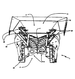
FIG. 1 represents a perspective, partially sectioned view of a rubble
crusher according to the invention;
FIGS. 2 and 3 represent details of the rubble crusher of FIG. 1.
Detailed description of an exemplary preferred embodiment
With reference to the figures above, and in particular to FIG. 1, a crusher 1
for elements to be recycled or disposed of according to the invention is
described and suitable for being controlled by a method according to the
invention. The crusher 1 is commonly used for crushing rubble deriving from
the
dismantling of masonry works, or other and similar works.
In this sense, it comprises a crushing chamber 2 in which the elements to
be recycled or disposed of are crushed. To this end, in the crushing chamber 2
is present a crushing assembly 3.
In the embodiment described, it consists of, as can be seen also in FIG. 2,
a pair of milling cutters 5 arranged frontally to each other and at least
partially
interpenetrating into each other. Among these, a crushing area 4 of the
elements to be recycled or disposed of can be identified.
According to an aspect of the invention, each milling cutter 5 comprises,
as shown in FIG. 3, a rotor 6 provided with a plurality of crushing disks 7.
The
latter are arranged coaxially with the rotation axis X of the rotor 6.
Moreover,
they are interspersed with spacers 8. In other words, between each adjacent
CA 03053459 2019-08-13
WO 2018/158668
PCT/IB2018/051130
6
pair of grinding disks 7 of each milling cutter 5 there is a slot 9 at a
spacer 8. In
this way, it is possible to partially interpenetrate the two milling cutters 5
arranged frontally so as a milling disk 7 of a milling cutter 5 is matched to
a
spacer 8 of the other.
Obviously, both the number of milling cutters and the effective
embodiment of the crushing assembly or of the milling cutters are to be
considered exemplary cases of the invention for different variant embodiments.
Also the number of crushing chambers and crushing assemblies are non-
limiting characteristics for the invention.
According to another aspect of the invention, the crusher 1 also comprises
a conveying channel 14 which, in the described embodiment, consists of a
loading hopper 15 for receiving the elements to be recycled or disposed of and
directs them towards the inside of the crushing chamber 2 in the direction of
the
crushing assembly 3. In the figures the crusher 1 has a vertical operating
configuration so that the elements to be recycled or disposed of are placed
above the hopper 15 from which they slide towards the crushing assembly 3.
Also this feature is to be considered non-limiting for different embodiments
of
the invention where the hopper is absent or where the working configuration of
the crusher is inclined or even horizontal, or where in a hopper there is a
further
element of the conveying channel having another shape.
During operation, the two milling cutters 5 are then rotated in opposite
directions so as to grasp the elements to be recycled or disposed of and to
crush them.
Since the crusher 1 must provide crushed elements to be recycled or
disposed with a smaller size than a predetermined size, typically it comprises
a
mechanism for adjusting this size. In the described exemplary embodiment, it
consists of an additional shaft 18 arranged at the outlet of the two milling
cutters
at a predetermined distance. In this way, the outgoing material, if it has
excessive size, can not descend, but is held close to the two milling cutters
5,
which continue with the crushing operation. Consequently, the distance
between the additional shaft 18 and the milling cutters 5 determines the
maximum size allowed for the elements to be recycled or disposed of at the
outlet of the crushing assembly 3.
CA 03053459 2019-08-13
WO 2018/158668
PCT/IB2018/051130
7
If among the elements to be recycled or disposed of sheet elements
and/or particularly tough elements are present, they could not get access to
the
crushing zone 4, but "float" above it. This, as mentioned, would force
operators
to intervene.
In order to avoid this eventuality, the crusher 1 of the invention comprises
two or more pushers 20 acting in the conveying channel 14 towards the
crushing assembly 3 to push the elements to be recycled or disposed of against
it.
In particular, the pushers 20 act on the elements to be recycled or
disposed of by pressing them against the crushing assembly 3 so that they are
totally crushed, in order to avoid advantageously their floatation.
According to another aspect of the invention, the crusher 1 also comprises
an amperometric sensor 22 for measuring the current consumption of the
crusher 1 itself, and a control circuit 23 operatively connected to the
amperometric sensor 22 and to the pushers 20.
Since the current absorbed by the crusher 1 is directly dependent on the
work it has to perform to crush the elements to be recycled or disposed of, it
is
an indicator of overload or particularly of the presence of tough elements
being
crushed.
Such cases are dangerous for the crusher 1 because it risks to be
damaged or in any case to stop, resulting in a need for a stop of the machine
in
order to solve the problem. In case of failure, the damage is evident. In case
of
arrest due to simple overload, the damage consists in the previously mentioned
unacceptable strong decrease in the yield of the same.
For this reason, if the measured current exceeds a first threshold value,
the control circuit 23 acts on the pushers 20 to decrease the intensity of the
push they exert.
In other words, advantageously, the overload of the crushing assembly 3
is immediately and automatically detected by means of the amperometric
sensor 22.
Still advantageously, the control circuit 23 in this case automatically acts
by limiting the push exerted by the pushers 20 thereby reducing the load on
the
crushing assembly 3.
CA 03053459 2019-08-13
WO 2018/158668
PCT/IB2018/051130
8
This allows the latter not only to be subjected to a lower effort, but also to
have time to dispose the elements to be recycled or disposed of, which are in
excess and those excessively tough.
This often allows to overcome the problem without stopping the production
of the crusher 1, but only by slowing it down.
In addition, the pushers 20 are controlled separately from each other in
order to partialize the push force and the push areas. This separate control
allows, therefore, to optimize the push reduction and maximize the production
speed.
In this way, still advantageously, the productivity is increased with respect
to the known equivalent crushers, since the situations which require it to
stop
are reduced. In the case of further downstream processing stations, however,
they too will be able to continue working, even if at reduced rates, instead
of
having to be stopped as in the prior art.
Still advantageously, the presence of the control circuit 23 allows to
reduce, and possibly eliminate at all, the need for the presence of personnel
in
charge of controlling and managing the crusher 1 of the invention with respect
to what happens for the known equivalent plants.
This still allows, advantageously, to further increase the yield of the
crusher 1 according to the invention by reducing operating costs.
Obviously, neither the number of amperometric sensors nor the number of
control circuits should be considered as limiting of the invention. According
to
some variant embodiments, for example, the amperometric sensors are more
than one and each associated with a respective milling cutter.
As previously mentioned, an object of the present patent is also the
method of controlling the crusher 1 described above.
In particular, according to an aspect of the invention, it comprises a step of
measuring the current absorbed by the crusher 1 and a step of comparing the
current value measured to the first predetermined value, which is a pre-alarm
threshold.
In the case the comparison provides an exceeding of the pre-alarm
threshold, then there is provided a step of reducing the push intensity
exerted
by the pushers 20so as to allow the crusher 1 to dispose of the excess
material
CA 03053459 2019-08-13
WO 2018/158668
PCT/IB2018/051130
9
and/or excessively tough material, and to restore the correct operation of the
crusher 1.
Subsequently, according to another aspect of the invention, the steps for
measuring the absorbed current and comparing the value of the current
measured to the first predetermined value are repeated.
If it is below the pre-alarm threshold, the adjustment of the pushers 20 is
reset.
Otherwise, this means that the problem is more serious and therefore an
opening step for at least one of the pushers is provided in order to zero
their
load to the crushing assembly 3.
In other words, a gradual discharge action of the crusher 1 is performed,
first decreasing the push of one or more of the pushers 20 separately from one
another and with intensities that are also different from each other, and
then, if
this is not sufficient, zeroing it at all.
This opening step is performed after a cycle of measurement steps of the
repetitive current for a predetermined number of times without the current
ever
falling below the pre-alarm threshold.
If the measured current does not drop and even rises above a second
predetermined value (corresponding to an alarm threshold), the control method
of the invention provides first of all a step of stopping the crusher 1 to
prevent it
from damage.
At the same time as the arrest, there is also provided an opening step of
all the pushers 20 not only to lighten the load on the crushing assembly 3,
but
also to be able to operate freely thereon.
According to a further aspect of the invention, moreover, after this
stopping step there is a first inversion step of the operation of the crusher
1 for a
predetermined time. In fact, the alarm situation could indicate the blockage
of
material too tough therewithin. The inversion of the processing could allow
the
release of this material from the crusher, releasing it.
Subsequently, the correct working direction of the crusher 1 is restored
and the current absorbed by it is measured. In case the values are back in the
norm, the normal functionality of the crusher 1 is restored.
Otherwise, the inversion step can be repeated several times. Obviously,
CA 03053459 2019-08-13
WO 2018/158668
PCT/1B2018/051130
even the number of times in which this repetition occurs can be any number,
without any limit for the present invention.
If this is not sufficient, according to another aspect of the invention, the
method also includes a step of modifying the calibration of the mechanism for
adjusting the size of the elements to be recycled or disposed of in order to
increase it. If this mechanism comprises the additional shaft 18, this
modification is obtained by increasing the distance from the output of the
milling
cutters 5.
In this way, the downstream output of the material being processed is
favoured, even if it has an excessive size.
If even this step is not sufficient to restore acceptable absorbed current
values, the method of the invention comprises a second inversion step of the
processing of the crusher 1, which can also be repeated for any number of
times without any limit for the present invention.
If at any time the absorbed current falls below the alarm and pre-alarm
values, the configuration of the crusher 1 is restored. If not, then a user
must
intervene to restore it.
It is therefore evident that the complete shut-down, in combination with the
user's intervention, occurs only in particular cases and that therefore the
productivity of the crusher 1 is certainly increased compared to the known
equivalent plants.
For this reason it is clear that the method of the invention of controlling a
crusher for elements to be recycled or disposed of, as well as the crusher
itself,
achieve all the intended purposes.
In particular, it allows reducing, if not zeroing, the risk of having to stop
it
during processing.
It also makes it possible to avoid or minimize the presence of specialized
personnel who monitor its operation.
Specifically, the crusher of the present invention has a processing yield
higher than the known equivalent crushers so as to minimize the costs in terms
of personnel to be dedicated to its operation and in economic terms.
The invention may be subject to many changes and variations, which are
all included in the appended claims. Moreover, all the details may furthermore
CA 03053459 2019-08-13
WO 2018/158668
PCT/IB2018/051130
11
be replaced by other technically equivalent elements, and the materials may be
different depending on the needs, without departing from the scope of
protection of the invention defined by the appended claims.