Note: Descriptions are shown in the official language in which they were submitted.
CA 03054094 2019-08-20
WO 2018/149594
PCT/EP2018/051537
1
A METHOD AND STIRRING SYSTEM FOR CONTROLLING AN
ELECTROMAGNETIC STIRRER
TECHNICAL FIELD
The present disclosure generally relates to metal making and in particular to
a method and a stirring system for controlling an electromagnetic stirrer.
BACKGROUND
Submerged Entry Nozzles (SEN) are used for controlling the flow pattern in a
slab caster mould, and consequently for the slab and final product quality. It
is a common practice to purge argon gas into the SEN for the purpose of
avoiding nozzle clogging due to oxides building up on the SEN inner wall and
for controlling flow the pattern in the mould.
With higher demand on product quality, several problems with conventional
SENs have been identified and a swirling flow nozzle has been considered as
one effective measure in improving the flow in the mould and thus to
improve the product quality.
Electromagnetic stirring of molten metal flowing through the tundish nozzle
has been under development for the last twenty years. The principle of an
electromagnetic stirrer arranged around the nozzle, is to generate a rotating
magnetic field in the nozzle. Eddy currents are thereby induced in the molten
metal flowing through the nozzle. This gives rise to an electromagnetic force
that rotates the molten metal horizontally in the SEN.
CN 100357049C discloses an electromagnetic swirl nozzle. An
electromagnetic swirl means is provided on a moving mechanism around the
nozzle, which moving mechanism is movable from the casting position.
SUMMARY
Although stirring by means of a rotating/traveling magnetic field in an SEN
may have beneficial effects on the end product, the present inventors have
CA 03054094 2019-08-20
WO 2018/149594
PCT/EP2018/051537
2
realised that even if electromagnetic stirring is used to provide stirring in
an
SEN, a number of additional parameters should be fulfilled in order to be
able to provide the desired higher quality end product.
In view of the above, an object of the present disclosure is to provide a
method of controlling an electromagnetic stirrer provided around an SEN
which solves, or at least mitigates, the problems of the prior art.
There is hence according to a first aspect of the present disclosure provided
a
method of controlling an electromagnetic stirrer arranged around a
submerged entry nozzle, SEN, of a tundish provided with a stopper rod to
to control throughput of the tundish, the SEN being configured to provide
tapping of molten metal from the tundish and the electromagnetic stirrer
being configured to generate a rotating magnetic field in the SEN, wherein
the method comprises: controlling the electromagnetic stirrer to operate only
when a gas flow rate through the stopper rod is in a first range of 1.5 NL/min
to 20 NL/min.
The inventors have found that by controlling the electromagnetic stirrer to
operate only when the gas flow rate is 1.5 NL/min or higher, a more efficient
electromagnetic stirring may be provided than for lower gas flow rates.
Furthermore, the inventors have found that operation of the electromagnetic
stirrer in combination with a higher gas flow rate than 20 NL/min can
generate a gas plug in the SEN, which could be harmful for the flow in the
mould and to the product quality. Thus, by only operating the
electromagnetic stirrer when the gas flow rate is in the first range, optimal
stirring in the SEN may be provided, ensuring, if all other is equal, a higher
quality end product.
With NL/min is meant normal litres per minute. With the term "operate" is
here meant that the electromagnetic stirrer is configured to provide a
rotating
magnetic field only when the gas flow rate through the stopper rod is in the
specified first range. The electromagnetic stirrer has coils which are
energised
to provide this rotating magnetic field, and thus, when electromagnetic
CA 03054094 2019-08-20
WO 2018/149594
PCT/EP2018/051537
3
stirrer is operated the coils are energised, thereby creating a rotating
magnetic field. The coils are typically not energised when the electromagnetic
stirrer is not being operated, at least not so that they will create a
rotating
magnetic field in the molten metal.
According to one embodiment the first range is 2 NL/min to 15 NL/min. The
range of 2 NL/min to 15 NL/min has proved to be especially advantageous in
being able to provide a higher quality end product.
According to one embodiment, in addition to the gas flow through the
stopper rod being in the first range, the controlling involves controlling the
electromagnetic stirrer to operate only when the casting throughput is at
least
1.5 ton/min. The inventors have found that if electromagnetic stirring is
applied when the throughput is less than 1.5 ton/min coalescence of the gas
bubbles may be promoted generating a gas plug in the SEN, which could be
harmful for the flow in the mould and for the product quality.
According to one embodiment the controlling involves controlling the
electromagnetic stirrer to operate only when the casting throughput is at
least
1.8 ton/min.
One embodiment comprises, prior to the step of controlling, obtaining a gas
flow rate through the stopper rod, wherein the controlling is based on the
obtained gas flow rate.
According to one embodiment the controlling of the electromagnetic stirrer
involves providing a controlled sub-meniscus speed of molten metal in a
mould in a second range of 0.20 m/s to 0.50 m/s.
According to one embodiment the second range is 0.25 m/s to 0.45 m/s.
One embodiment comprises obtaining a sub-meniscus speed of molten metal
in the mould, wherein the controlling is based on the obtained sub-meniscus
speed.
According to one embodiment the gas is argon gas.
CA 03054094 2019-08-20
WO 2018/149594
PCT/EP2018/051537
4
There is according to a second aspect of the present disclosure provided a
stirring system for a metal-making process, comprising: an electromagnetic
stirrer configured to be arranged around a submerged entry nozzle, SEN, of a
tundish provided with a stopper rod to control throughput of the tundish,
and a control system configured to control the electromagnetic stirrer to
operate only when a gas flow rate through the stopper rod is in a first range
of
1.5 NL/min to 20 NL/min.
According to one embodiment the first range is 2 NL/min to 15 NL/min.
According to one embodiment, in addition to the gas flow through the
stopper rod being in the first range, the control system is configured to
control the electromagnetic stirrer to operate only when the casting
throughput is at least 1.5 ton/min.
According to one embodiment the control system is configured to control the
electromagnetic stirrer to operate only when the casting throughput is at
least
1.8 ton/min.
According to one embodiment the control system is configured to control the
electromagnetic stirrer to provide a controlled sub-meniscus speed of molten
metal in a mould in a second range of 0.20 m/s to 0.50 m/s.
According to one embodiment the second range is 0.25 m/s to 0.45 m/s.
One embodiment comprises power source configured to power the
electromagnetic stirrer, wherein the control system is configured to control
the power source to thereby control the electromagnetic stirrer.
One embodiment comprises a sensor configured to measure a sub-meniscus
speed of molten metal in a mould into which the SEN is configured to be
lowered, wherein the control system is configured to control the power source
based on a sub-meniscus speed measured by the sensor.
According to one embodiment the sensor comprises a ceramic rod configured
to be immersed in molten metal, the sensor being configured to measure a
CA 03054094 2019-08-20
WO 2018/149594
PCT/EP2018/051537
torque on the ceramic rod, wherein the control system is configured to
control the power source based on the torque.
Generally, all terms used in the claims are to be interpreted according to
their
ordinary meaning in the technical field, unless explicitly defined otherwise
5 herein. All references to "a/an/the element, apparatus, component, means,
etc. are to be interpreted openly as referring to at least one instance of the
element, apparatus, component, means, etc., unless explicitly stated
otherwise.
BRIEF DESCRIPTION OF THE DRAWINGS
The specific embodiments of the inventive concept will now be described, by
way of example, with reference to the accompanying drawings, in which:
Fig. 1 schematically shows a block diagram of a control system;
Fig. 2 schematically shows an assembly for metal-making including the
control system in Fig. 1; and
Fig. 3 shows a flowchart of a method of controlling an electromagnetic stirrer
by means of the control system in Fig. 1.
DETAILED DESCRIPTION
The inventive concept will now be described more fully hereinafter with
reference to the accompanying drawings, in which exemplifying
embodiments are shown. The inventive concept may, however, be embodied
in many different forms and should not be construed as limited to the
embodiments set forth herein; rather, these embodiments are provided by
way of example so that this disclosure will be thorough and complete, and
will fully convey the scope of the inventive concept to those skilled in the
art.
Like numbers refer to like elements throughout the description.
The present disclosure relates to a method of controlling an electromagnetic
stirrer by means of a control system. The method is for use in a metal-making
process, typically a continuous casting process, for example a steel-making
CA 03054094 2019-08-20
WO 2018/149594
PCT/EP2018/051537
6
process, an aluminium-making process, a lead-making process or a metal-
alloy making process. The method may be configured to be used with a billet
caster, a bloom caster or a slab caster.
The electromagnetic stirrer is of a type that is configured to be arranged
around a submerged entry nozzle (SEN) of a tundish. The electromagnetic
stirrer is hence configured to provide stirring of molten metal flowing
through the SEN. The electromagnetic stirrer is thus of a type which extends
circumferentially around the SEN.
The tundish comprises the SEN and a stopper rod, which has an axial
to channel through which a gas is able to flow to control the casting
throughput
of the tundish. The gas is typically argon gas.
The method involves controlling the electromagnetic stirrer by means of the
control system so that the electromagnetic stirrer is only in operation when
the gas flow rate through the stopper rod is in a first range of 1.5 NL/min to
20 NL/min. The first range may for example be 2 NL/min to 15 NL/min. To
this end, the control system is configured to control the electromagnetic
stirrer so that it generates a rotating magnetic field in the molten metal
flowing through the SEN only when the gas flow rate through the stopper rod
is in the first range.
With reference to Fig. 1, an example of a control system configured to control
an electromagnetic stirrer will now be described. The exemplified control
system 1 comprises processing circuitry 3 and a storage medium 5 comprising
computer-executable components which when executed by the processing
circuitry 3 causes the control system 1 to perform the method as disclosed
herein.
The processing circuitry 3 uses any combination of one or more of a suitable
central processing unit (CPU), multiprocessor, microcontroller, digital signal
processor (DSP), application specific integrated circuit (ASIC), field
programmable gate arrays (FPGA) etc., capable of executing any herein
disclosed operations concerning the control of an electromagnetic stirrer.
CA 03054094 2019-08-20
WO 2018/149594
PCT/EP2018/051537
7
The storage medium 5 may for example be embodied as a memory, such as a
random access memory (RAM), a read-only memory (ROM), an erasable
programmable read-only memory (EPROM), or an electrically erasable
programmable read-only memory (EEPROM) and more particularly as a
non-volatile storage medium of a device in an external memory such as a
USB (Universal Serial Bus) memory or a Flash memory, such as a compact
Flash memory.
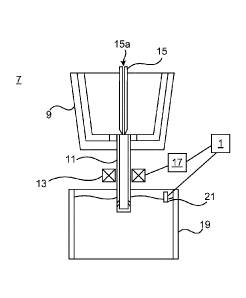
Fig. 2 shows an example of an environment in which the control system 1
operates when controlling an electromagnetic stirrer. Assembly 7 is used in a
metal-making process and comprises a tundish 9, which is a metallurgical
vessel provided with a bottom tapping hole, an SEN 11 configured to provide
tapping of molten metal from the tundish 9, in particular via the bottom
tapping hole, and a stopper rod 15. The SEN 11 may be monolithic or non-
monolithic.
The assembly 7 also includes a stirring system comprising an electromagnetic
stirrer 13 configured to be mounted around the SEN ii and the control
system 1. The stirring system also includes a power source 17 which is
configured to power the electromagnetic stirrer 13. The power source 17 may
for example be a power converter, such as an AC/AC converter or a DC/AC
converter. The control system 1 is configured to control the power source 17
to thereby control the electromagnetic stirrer 13. In this manner, the
rotating
magnetic field applied to the SEN 11 may be controlled. The electromagnetic
force that rotates the molten metal flowing through the SEN 11 may hence be
controlled.
The electromagnetic stirrer 13 may be configured to be fixedly mounted
relative to the tundish and relative to the SEN or it may be movably mounted
relative to the SEN. In the former case, the electromagnetic stirrer is
configured to be mounted immovably relative to the tundish and the SEN. In
particular, the electromagnetic stirrer is in this case configured to be
mounted to a fixed structure, which is fixed relative to the tundish and
relative to the SEN. This fixed structure may for example be the tundish
CA 03054094 2019-08-20
WO 2018/149594
PCT/EP2018/051537
8
itself, for example the tundish bottom, an SEN-cutting device mounted to the
tundish bottom, or a locking device, typically configured to attach and lock
two longitudinally extending nozzle parts of an SEN together.
The electromagnetic stirrer 13 may be a closed-type electromagnetic stirrer,
.. in the sense that it has no moving parts in the portion surrounding the SEN
ii. The electromagnetic stirrer 13 may have a closed and integral SEN-
enclosing portion, or annular end portion configured to surround the SEN 11.
According to this example, the electromagnetic stirrer 13 is non-openable.
The annular end portion is thus integrated, although it should be understood
that the annular end portion may comprise a number of distinct components,
such as a magnetic core and coils wound around the core. The annular end
portion forms a channel configured to receive the SEN ii. This channel may
be said to be seamless in the circumferential direction, along the inner
circumference of the channel. In case the electromagnetic stirrer 13 is of a
closed type, the electromagnetic stirrer 13 cannot during installation be
opened and placed around the SEN 11 from two sides of the SEN 11, before
closing. Instead, during installation, the electromagnetic stirrer 13 is
threaded over the SEN 11 in the axial direction thereof. The SEN-enclosing
portion provides a circumferentially closed and integral annular passage
through which the SEN is configured to extend. The closed and integrated
SEN-enclosing portion has no moving parts, which prolongs the lifetime of
the electromagnetic stirrer. Compared to open-type electromagnetic stirrers,
a higher magnetic field strength may be obtained, and magnetic leakage may
be reduced.
.. According to another variation, the electromagnetic stirrer 13 may be
openable. The electromagnetic stirrer 13 may in this case have an SEN-
enclosing portion which is openable. The SEN-enclosing portion may for
example be hinged, or the electromagnetic stirrer 13 may comprise two
separable halves which may be placed around the SEN 11, wherein the halves
are assembled with each other.
CA 03054094 2019-08-20
WO 2018/149594
PCT/EP2018/051537
9
In use of the assembly 7, molten metal is tapped into the tundish 9 from a
ladle. The flow of molten metal discharged from the tundish may be
controlled through the SEN 11, typically by means of the stopper rod 15. The
stopper rod 15 has a gas inlet and a gas outlet, connected by means of a
channel 15a extending in the longitudinal direction to enable a gas to flow
from the gas inlet through the stopper rod 15 to the gas outlet, and into the
SEN 11 which is arranged aligned with but downstream of the stopper rod 15.
The flow of molten metal may thus be controlled in the SEN 11 to avoid
nozzle clogging. The stopper rod 15 is additionally configured to be moved
vertically up and down to regulate the flow-rate of the molten metal flowing
from the tundish 9 to the mould 19 via the SEN 11.
Below the tundish 9 there is provided a mould 19 into which the SEN 11
extends and from which molten metal is discharged into the mould 19. The
molten metal is partially solidified in the mould 19. The partially solidified
metal is then moved by gravity from the mould 19, normally through an
arrangement of rollers for shaping and for cooling. In this manner, billets,
blooms or slabs may be obtained.
Referring to Fig. 3, the operation of the control system 1 will now be
described. In a step Si the electromagnetic stirrer 13 is controlled to
operate
only when the gas flow rate through the stopper rod 15 is in a first range of
1.5
NL/min to 20 NL/min, the first range preferably being between 2 NL/min
and 15 NL/min. As noted above, this control is provided by the control
system 1.
During casting, the gas flow rate is beneficially controlled to be higher than
1.5 NL/min, preferably at least 2 NL/min in order to obtain an improved
mould flow due to the provision of electromagnetic stirring in the SEN. The
gas flow rate is beneficially controlled to be lower than 20 NL/min,
preferably
not higher than 15 NL/min. A higher gas flow rate than 20 NL/min in
combination with electromagnetic stirring in the SEN may generate a gas
plug in the SEN, which could be harmful for the flow in the mould and for the
product quality. The gas flow rate may be controlled by means of the control
CA 03054094 2019-08-20
WO 2018/149594
PCT/EP2018/051537
system 1 or by another controller dedicated to control the gas flow rate
through the stopper rod 15.
The control system 1 may be configured to obtain a gas flow rate of the gas
flowing through the stopper rod before step Si. The gas flow rate may for
5 example be obtained from measurements by one or more gas flow rate
sensor(s) and/or by means of estimation. The step Si of controlling is then
based on the obtained gas flow rate.
Moreover, step Si may involve an additional constraint, namely that of a
minimum casting throughput of 1.5 ton/min, preferably 1.8 ton/min. Hereto,
10 the control system 1 may be configured to control the electromagnetic
stirrer
13 to operate only when the gas flow rate through the stopper rod 15 is in the
first range and when the casting throughput is at least 1.5 ton/min,
preferably
at least 1.8 ton/min.
Applying electromagnetic stirring on the SEN ii with throughput less than
1.8 ton/min can promote coalescence of the gas bubbles and generate a gas
plug in the SEN ii which could be harmful for the flow in the mould and for
the product quality.
According to one example, step Si of controlling the electromagnetic stirrer
13 may involve providing a controlled sub-meniscus speed of molten metal in
a mould in a second range of 0.20 m/s to 0.50 m/s, the second range
preferably being between 0.25 m/s and 0.45 m/s. In particular, the control
target of the electromagnetic stirrer 13 may be to reach a double roll metal
flow pattern in the mould and a controlled sub-meniscus speed in the second
range. Hereto, the control system 1 may be configured to control the
electromagnetic stirrer 13, by means of the power source 17 to reach this
control target.
The stirring system may also include a sensor 21. The sensor 21 is configured
to provide online measurements of casting parameters, typically of a sub-
meniscus speed or velocity. The sensor 21 may be configured to measure a
sub-meniscus speed of molten metal in the mould 19. The control system 1
CA 03054094 2019-08-20
WO 2018/149594
PCT/EP2018/051537
11
may be configured to control the power source 17, and thus the
electromagnetic stirrer 13, based on the sub-meniscus speed measured by the
sensor 21 to attain a desired setpoint value of the sub-meniscus speed.
The sensor 21 may for example include a ceramic rod configured to be
submerged in molten metal in the mould 19. The sensor 21 may be configured
to measure the torque applied to the ceramic rod. The torque provides a
measure of the sub-meniscus speed. The control system 1 may be configured
to evaluate a torque measured by the sensor 21 and to convert it to a sub-
meniscus speed. The control system 1 may be configured to control the power
source 17 based on the sub-meniscus speed obtained.
As an alternative to the above-described torque measurement, the wave
height of the meniscus may be measured, and the control system 1 may be
configured to evaluate the wave height to obtain an estimate of the sub-
meniscus speed.
As yet another alternative, the metal throughput may be measured online, or
the metal throughput and the argon gas flow through the stopper rod 6 may
be measured or estimated and used as basis for controlling the
electromagnetic stirrer 13 by means of the control system 1.
According to one example, the control system 1 is configured to control the
power source 17 so that the electromagnetic stirrer 7 provides a rotating
magnetic field which generates an electromagnetic force in the molten metal
which rotates the molten metal at least one turn, typically more than one
turn, as it flows from one end of the SEN 11 to the other end of the SEN 11,
in
the longitudinal direction of the SEN 11.
The inventive concept has mainly been described above with reference to a
few examples. However, as is readily appreciated by a person skilled in the
art, other embodiments than the ones disclosed above are equally possible
within the scope of the inventive concept, as defined by the appended claims.