Note: Descriptions are shown in the official language in which they were submitted.
IMPROVED ANEURYSM OCCLUSION DEVICE
CROSS-REFERENCE TO RELATED APPLICATIONS
This application is a continuation in part of U.S. patent application serial
number
14/230,426, filed on March 31, 2014, the content of which is incorporated
herein by reference in
its entirety.
BACKGROUND OF THE INVENTION
1. Field of Invention
The invention relates to implants within body vessels and more particularly to
occlusion devices for small vascular openings such as a neck of an aneurysm.
2. Description of the Related Art
Vascular disorders and defects such as aneurysms and other arterio-venous
malformations
are especially difficult to treat when located near critical tissues or where
ready access to a
malformation is not available. Both difficulty factors apply especially to
cranial aneurysms. Due
to the sensitive brain tissue surrounding cranial blood vessels and the
restricted access, it is very
challenging and often risky to surgically treat defects of the cranial
vasculature.
In the treatment of aneurysms by endovascular implants, the goal is to exclude
the internal
volume of the aneurysm sac from arterial blood pressure and flow. As long as
the interior walls of
the aneurysm are subjected to blood pressure and/or flow, there is a risk of
the aneurysm rupturing.
Non-surgical treatments include vascular occlusion devices such as embolic
coils deployed
using catheter delivery systems. In a currently preferred procedure to treat a
cranial aneurysm, the
distal end of an embolic coil delivery catheter is initially inserted into non-
cranial vasculature of a
patient, typically through a femoral artery in the groin, and guided to a
predetermined delivery site
1
CA 3054188 2019-09-05
in a blood vessel within the cranium. The aneurysm sac is then filled with
embolic material that
causes formation of a solid, thrombotic mass that protects the walls from
blood pressure and flow.
Preferably, the thrombotic mass substantially restores the original blood
vessel shape along the
plane of the aneurysm's neck. The neck plane is an imaginary surface where the
intima of the blood
vessel would be if not for formation of the aneurysm. However, simply
utilizing embolic coils is
not always effective at treating aneurysms as re-canalization of the aneurysm
and/or coil
compaction can occur over time.
A bag for use in an aneurysm sac is described by Greenhalgh in US Patent Nos.
6,346,117
and 6,391,037, and an aneurysm neck obstruction device is shown in US Patent
No. 6,454,780 by
Wallace. Detachable neck bridges are disclosed by Abrams et al. in US Patent
No. 6,036,720 and
by Murphy et al. in US Patent No. 7,410,482 for example. Preferably, one or
more embolic coils
are delivered within or through the neck bridges or other obstruction devices
to fill the sac of the
aneurysm.
Yet another type of vaso-occlusive device is illustrated in US Patent No.
5,645,558 by
Horton as having one or more strands of flexible material which are wound to
form a generally
spherical or ovoid vaso-occlusive structure when relaxed after being placed in
a vascular cavity
such as an aneurysm or fistula. Similarly, US Patent No. 5,916,235 by
Guglielmi cites earlier
patents describing detachable coils and then discloses an expandable cage as a
vaso-occlusive
structure that can receive and retain one or more coils after the cage is
expanded within an
aneurysm. A self-expandable aneurysm filling device is disclosed in US Patent
Publication No.
2010/0069948 by Veznedaroglu et al.
2
CA 3054188 2019-09-05
It is therefore desirable to have a retrievable, repositionable device that
cooperates with
one or more embolic coils or other vaso-occlusive structure to effectively
occlude a neck of an
aneurysm or other arterio-venous malformation in a blood vessel.
SUMMARY OF THE INVENTION
An object of the present invention is to provide an improved occlusion device
which
substantially blocks flow into an aneurysm in a blood vessel.
Another object of the present invention is to provide such an occlusion device
which can
be repositioned or retrieved from a sac of an aneurysm.
This invention features an occlusion device suitable for endovascular
treatment of an
aneurysm in a blood vessel in a patient, including a substantially tubular
structure having a
proximal end region and a distal end region, having a first, expanded
condition and a second,
collapsed condition. The device has dimensions in the second, collapsed
condition suitable for
insertion through vasculature of the patient and through a neck of the
aneurysm. The device further
includes a control ring having a substantially annular body disposed on the
proximal end region of
the structure and at least substantially circumscribing the proximal end
region to prevent radial
expansion of the proximal end region and to provide an engagement feature
during manipulation
of the occlusion device.
In a number of embodiments, the control ring defines an inner passage, such as
a channel
established by an inner sleeve, through which at least one embolic coil is
insertable into the
aneurysm. Preferably, at least a portion of the proximal end region of the
tubular structure defines
a plurality of openings having a sufficiently small size to enhance occlusion
of the aneurysm. In
3
CA 3054188 2019-09-05
some embodiments, the tubular structure cooperates with at least one vaso-
occlusion structure such
as a collapsible cage-like device.
In certain embodiments, the occlusive device is capable of being utilized in
combination
with a delivery member defining an inner lumen and having a distal end region
carrying a grabber
having at least two finger elements, each finger element defining a gripping
region to mechanically
engage the control ring. In one embodiment, the grabber is formed of a
metallic material and the
gripping regions are notches formed in the finger elements, each notch being
sized to mechanically
engage a portion of the control ring. The combination may further include a
catheter having an
inner lumen through which the delivery tube is insertable and translatable
relative to the catheter.
This invention may also be expressed as a method of treating an aneurysm in a
blood vessel
in a patient, the method including selecting an occlusion device with a
structure having a
substantially tubular structure having a proximal end region and a distal end
region, having a first,
expanded condition and a second, collapsed condition, and having dimensions in
the second,
collapsed condition suitable for insertion through vasculature of the patient
and through a neck of
the aneurysm. The device further includes a control ring having a
substantially annular body
disposed on the proximal end region of the structure and at least
substantially circumscribing the
proximal end region to prevent radial expansion of the proximal end region.
In some embodiments, the method further includes mechanically engaging the
control ring
with a grabber on a delivery tube to enable manipulation of the occlusion
device, drawing the
occlusion device into a catheter carrying the delivery tube to force the
occlusion device into the
collapsed condition, inserting the catheter with the occlusion device into
vasculature of the patient
to reach the region of the aneurysm in the blood vessel, and positioning the
occlusion device within
the aneurysm.
4
CA 3054188 2019-09-05
In certain embodiments, the method additionally includes delivering at least
one embolic
coil through the delivery tube and through the control ring to secure the
occlusion device within
the aneurysm to occlude flow into the aneurysm, and mechanically releasing the
control ring and
withdrawing the catheter and the delivery tube from the patient. In yet other
embodiments, the
method further includes selecting the occlusive device to be attached to a
collapsible cage-like
vaso-occlusive structure, and positioning the occlusive device within the
aneurysm includes
utilizing the vaso-occlusive structure to secure the proximal end region of
the tubular structure
across the neck of the aneurysm.
BRIEF DESCRIPTION OF THE DRAWINGS
In what follows, preferred embodiments of the invention are explained in more
detail with reference to the drawings and photographs, in which:
FIG. 1 is a schematic side cross-sectional view of an inventive occlusion
device within a
novel catheter delivery system positioned at the neck of an aneurysm of a
blood vessel;
FIG. 2 is an enlarged schematic side view of the delivery system of FIG. 1
showing the
occlusion device held in a collapsed condition;
FIG. 3 is a schematic side view similar to FIG. 1 showing the occlusion device
according
to the present invention expanding within the sac of the aneurysm while still
being securely held
by the delivery system;
FIG. 4 is a schematic side view similar to FIG. 3 showing an embolic coil
being advanced
through the delivery system and the occlusion device into the aneurysm;
FIG. 5 is a schematic side view similar to FIG. 2 with the microcatheter
withdrawn
proximally to allow grasper fingers to release the control ring of the
occlusion device;
CA 3054188 2019-09-05
FIG. 6 is a schematic side cross-sectional view similar to FIG. 4 after the
delivery system
has been withdrawn and with embolic coils securing the occlusion device within
the sac of the
aneurysm;
FIG. 7 is a schematic cross-sectional view of a spherical mandrel establishing
the first,
expanded condition for at least one an occlusion device according to the
present invention;
FIGS. 8A and 8B are schematic side views of two hemi-spherical occlusion
devices
according to the present invention derived from the occlusion device of FIG.
7;
FIG. 9 is a schematic side view of a single occlusion device after the mandrel
of
FIG. 7 has been removed;
FIG. 10 is a schematic side view similar to FIG. 9 after a distal portion of
the occlusion
device has been removed to generate an alternative open configuration;
FIG. 11 is a side view similar to FIG. 10 of an alternative occlusion device
formed utilizing
an elliptical, lozenge-shaped mandrel;
FIG. 12 is a view similar to FIG. 3 showing the occlusion device cooperating
with a cage-
like vaso-occlusive structure within an aneurysm;
FIG. 13 is an enlarged schematic side view of an alternative delivery system
for devices
similar to those shown in FIG. 12 with an occlusion device and a vaso-
occlusive structure held in
a collapsed condition being advanced into an aneurysm;
FIG. 14 is a schematic side cross-sectional view similar to FIG. 13 after the
delivery system
has been withdrawn, and with the vaso-occlusive structure securing the
occlusion device within
the sac of the aneurysm;
6
CA 3054188 2019-09-05
FIG. 15 is a schematic side cross-sectional view of an inventive occlusion
device within a
novel catheter delivery system positioned at the neck of an aneurysm of a
blood vessel and a
catheter for delivering an embolic device inserted into the aneurysm sac;
FIG. 16 is a schematic side cross-sectional view showing the occlusion device
of FIG. 15
positioned at the neck of an aneurysm of a blood vessel in a partially
implanted condition and a
catheter for delivering an embolic device inserted into the aneurysm sac;
FIG. 17A is a schematic side view showing the occlusion device of FIG. 16
expanded
within the sac of the aneurysm while still being securely held by the delivery
system and the
catheter for delivering the embolic device jailed between the expanded
occlusion device and a wall
of the aneurysm;
FIG. 17B is a cross-sectional view of the expanded occlusion device and jailed
catheter of
FIG. 17A;
FIG. 18 is a schematic side view showing the expanded occlusion device of FIG.
17A and
an embolic coil being advanced through the embolic delivery catheter and the
occlusion device
into the aneurysm;
FIG. 19 is a schematic side view showing the expanded occlusion device of FIG.
18 after
completion of implantation and removal of catheters; and
FIG. 20 is a schematic side view showing the release of an expanded occlusion
device such
as the occlusion device illustrated in FIGs. 15-19.
DETAILED DESCRIPTION OF THE PRESENTLY PREFERRED EMBODIMENTS
7
CA 3054188 2019-09-05
This invention may be accomplished by an occlusion device suitable for
endovascular
treatment of an aneurysm in a blood vessel in a patient, with a substantially
tubular structure having
a proximal end region and a distal end region, having a first, expanded
condition and a second,
collapsed condition. The device has dimensions in the second, collapsed
condition suitable for
insertion through vasculature of the patient, utilizing a catheter such as a
microcatheter, and
through a neck of the aneurysm. The device further includes a control ring
having a substantially
annular body disposed on the proximal end region of the structure and at least
substantially
circumscribing the proximal end region to prevent radial expansion of the
proximal end region and
to provide an engagement feature during manipulation of the occlusion device.
The control ring is releasably engageable by a releasable feature such as a
grabber or at
least one frangible member on a delivery member in some mechanical
constructions or, in other
constructions, by at least one electrolytically severable element. Preferably,
the control ring defines
an inner passage through which at least one embolic coil is insertable into
the aneurysm. In another
construction, the occlusion device is held in place within the aneurysm by at
least one vaso-
occlusive structure such as a cage-like device.
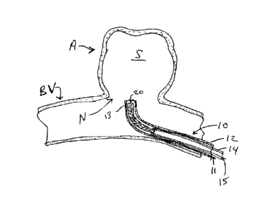
FIG. 1 schematically illustrates the distal portion of a novel delivery system
10 including
a microcatheter 12 and a delivery tube 14 holding a tubular occlusion device
20 according to the
present invention to be implanted within sac S of aneurysm A emerging from
blood vessel By. In
one construction, the microcatheter 12 has a distal radiopaque marker band 13
and is advanced to
the vicinity of neck N of aneurysm A such that marker band 13 is at the level
of the neck N as seen
under fluoroscopy.
Enlarged views of the distal portion of delivery system 10 and of occlusion
device 20 are
provided in FIGS. 2 and 5. Occlusion device 20 is shown in a second, collapsed
condition in FIG.
8
CA 3054188 2019-09-05
2 within catheter lumen 11, with a control ring 22 held by grabber 30 of
delivery tube 14. Control
ring 22 is disposed about a proximal region 23 of device structure 25 and
defines an inner passage
26 through which one or more embolic coils are inserted, as described in more
detail below.
Structure 25 of occlusion device 20 further includes a mesh body 24 and a
distal region 28.
After the delivery system 10 is positioned as shown in FIG. 1, the delivery
tube 14 is
advanced within lumen 11 of catheter 12 to enable occlusion device 20 to
expand into an
approximately hemi-spherical shape within sac S as shown in FIG. 3. The shape
of occlusion
device 20 will conform to the shape of the sac S where device 20 touches the
inner wall of the sac
S. Grabber 30 continues to be constrained radially by lumen 11 of catheter 12
and maintains its
grip on control ring 22 with a plurality of gripping regions such as notches
36 and 38, FIG. 5. In
one construction, control ring 22 is radiopaque and is aligned under
fluoroscopy relative to marker
13 on catheter 12 as shown in FIGS. 3 and 4.
Once occlusion device 20 is positioned within sac S, at least one embolic coil
40, FIG. 4,
is advanced through lumen 15 of delivery tube 14 as indicated by arrow 42,
through passage 26 of
control ring 22 as indicated by arrow 44, and is advanced, arrow 46, within
aneurysm A to
substantially fill sac S and to anchor body 24 of occlusion device 20 against
the interior wall of
aneurysm A to block neck N as shown in FIG. 6.
After a sufficient amount of embolic coil 40 has been fully deployed within
sac S to anchor
occlusion device 20 within aneurysm A, the catheter 12 is withdrawn
proximally, as indicated by
arrow 51 in FIG. 5, while maintaining delivery tube 14 in place, to remove
radial constraint on
fingers 32 and 34 of grabber 30. Fingers 32 and 34 preferably are biased
radially outwardly and
move in the direction of arrows 50 and 52, respectively, to disengage control
ring 22 from notches
36 and 38 in fingers 32 and 34, respectively.
9
CA 3054188 2019-09-05
In one construction, the catheter 12 is a polymeric microcatheter defining an
inner lumen
11 having an inner diameter of between 0.020 inch and 0.027 inch, the delivery
tube 14 has outer
diameter that is slightly less than the inner diameter of the catheter lumen
11, and the grabber 30
with occlusion device 20 in the collapsed condition shown in FIGS. 1 and 2
also have outer
diameters that are substantially the same as the inner diameter of the
catheter lumen 11, which
radially constrains fingers 32 and 34 to engage control ring 22. The lumen 15
of delivery tube 14
has a diameter capable of allowing passage of a conventional embolic coil
delivery system having
a nominal outer diameter of between 0.010 inch and 0.015 inch.
In some constructions, the delivery tube has at least one region of increased
flexibility,
especially near the distal end of the delivery tube, to minimize unintended
microcatheter
movement during translation of the delivery tube relative to the
microcatheter. The at least one
flexible region is made in one construction by laser-cutting a pattern of
interrupted cuts into a
medical-grade nitinol (NiTi) tube. In other constructions, a coiled metallic
or polymeric cylindrical
component and/or a cylindrical section of flexible polymeric material is added
to the distal region
of the delivery tube. The grabber is created in some constructions by laser-
cutting material forming
the grabber to create at least two finger elements, each preferably having a
notch to enhance
gripping of a control ring according to the present invention. In certain
constructions, the grabber
is integral, that is, is monolithically formed with the same material as the
remainder of the delivery
tube and, in other constructions, is fixedly attached to the distal end of the
delivery tube.
In one construction, the structure 25 of occlusion device 20 is formed of
metallic filaments
that establish an expandable braided mesh tube. Suitable materials for the
filaments include nitinol
wires and other biocompatible metals, such as platinum, that will not remain
in a collapsed
condition after being ejected from a delivery tube. Preferably, at least one
platinum wire is included
CA 3054188 2019-09-05
for radiopacity. In other constructions, the structure 25 is formed of at
least one polymeric material
that does not become "set" in the collapsed condition.
Suitable materials for control ring 22 discussed above, and for control ring
22a and band
22b discussed below in relation to FIGS. 7-8B, include biocompatible
radiopaque materials such
as platinum, tantalum and gold. Other suitable metallic materials include
cobalt chromium,
stainless steel, and combinations of two or more of biocompatible metals.
Suitable polymeric
materials include biocompatible biodegradable and non-biodegradable materials,
as described in
more detail below.
One technique for manufacturing an occlusion device according to the present
invention is
illustrated in FIG. 7. After structure 25a is formed as a braided mesh tube, a
control ring 22a is
disposed by crimping and/or welding ring material about proximal region 23a to
limit radial
expansion at that site while defining an inner passage 26a through which one
or more embolic
coils can be inserted, as described above. Optionally, an inner sleeve such as
a grommet (not
shown) is inserted within structure 25a and positioned under the control ring
23a to maintain an
inner diameter opening of desired dimension for inner passage 26a.
In this technique, a spherical mandrel 60 such as a steel ball bearing is
inserted through
distal region 28a to enlarge and expand the structure 25a in body region 24a.
A clamp-like element
such as a band 22b is then crimped over distal region 62 to further shape the
body 24a. In some
techniques, the assembly is heated to set mesh body 24a in the expanded
condition.
When two hemispherical occlusion devices are desired, a cut is made along the
circumference of mandrel 60, typically equidistant between control ring 22a
and band 22b as
indicated by dashed line 63, as well as on the opposite sides of control ring
22a and band 22b as
shown by arrows 64 and 66, respectively. This technique creates two separate
devices 20a and
11
CA 3054188 2019-09-05
20b, as depicted in FIGS. 8A and 8B, respectively. Distal end regions 28a and
28b are both open,
such as illustrated for device 20 in FIGS. 1-6. Device 20b also has body 24b,
proximal region 23b,
and a passage 26b formed by band 22b which serves as a control ring according
to the present
invention. In other words, band 22b is incorporated into an implantable device
20b in one
construction, instead of being a temporary clamp.
In alternative techniques, band 22b is removed and mandrel 60, FIG. 7, is
extracted to form
the occlusion device 20c, FIG. 9, with a constricted yet un-constrained distal
region 28c, having a
single control ring 22a. In yet another technique, a cut is made non-
equatorially about structure
25a, such as along line 70, to generate device 20d, FIG. 10. In yet other
constructions, a non-
spherical mandrel such as a lozenge-shaped mandrel, is utilized to form an
elongated device 20e,
FIG. 11. In other words, the occlusion device according to the present
invention can have many
shapes such as round, elliptic, oblong, or otherwise asymmetric, and can have
an open or a closed
distal end. It is expected that an open distal end will typically allow better
conformance to the neck
and sac of the aneurysm to be treated.
An alternative occlusion device 20f according the present invention is
illustrated in FIG. 12
cooperating with a cage-like vaso-occlusive structure 80 formed of strands 82,
84, 86, 88, 90, 92
and 94 in this construction. In some constructions, vaso-occlusive structure
80 is similar to one of
the embodiments disclosed in US Patent No. 5,645,558 by Horton and, in certain
other
constructions, is similar to one of the embodiments disclosed in US Patent No.
5,916,235 by
Guglielmi and in US Patent Publication No. 2010/0069948 by Veznedaroglu et al.
After a delivery system 10f is positioned as desired relative to aneurysm A,
an elongated
delivery member 14f is advanced within lumen Ilf of catheter 12f to enable
occlusion device 20f
and vaso-occlusive structure 80 to expand within sac S as shown in FIG. 12. In
this construction,
12
CA 3054188 2019-09-05
a grabber 30f continues to be constrained radially by lumen llf of catheter
12f and maintains its
grip on control ring 22f with a plurality of gripping regions. In one
construction, control ring 22f
is radiopaque and is aligned under fluoroscopy in a similar manner as
described above relative to
FIGS. 3 and 4.
Once vaso-occlusive structure 80 is fully deployed in an expanded condition
within sac S,
structure 80 presses occlusion device 20f against the interior wall and across
the neck N of
aneurysm A to secure it in place. In other words, vaso-occlusive structure 80
serves in an expanded
condition as a frame or lattice to anchor occlusion device 20f against neck N,
and occlusion device
20f, held in place by structure 80, serves as a cover extending at least
across neck N, the cover
preferably being porous or otherwise defining sufficiently small openings, to
enhance occlusion
of aneurysm A. Preferably, occlusion device 20f is secured to vaso-occlusive
structure 80 by at
least one attachment point, being attached to at least one of a portion of the
interior surface of
device 20f and a portion of the control ring 22f, to maintain an aligned
relationship between the
device 20f and the structure 80, especially during loading and delivery of
structure 80 and device
20f utilizing a delivery cannula.
In certain techniques, if a surgeon or other user desires to substantially
fill the interior of
sac S, at least one embolic coil is advanced through lumen 15f of delivery
tube 14f, through a
passage in control ring 22f, and then is advanced into aneurysm A. In other
constructions, for use
where insertion of one or more embolic coils is not desired, control ring 22f
may lack a passage.
In yet other constructions, such as illustrated in FIGS. 13-14, an occlusion
device 20g has
a detachment feature 98, representing a conventional detachment joint, instead
of a control ring.
Examples of electrolytically severable joints and mechanical joints are
described in US Patent No.
6,454,780 by Wallace and in US Patent No. 7,410,482 by Murphy et al., for
example. Similar
13
CA 3054188 2019-09-05
detachable joints are described in US Patent No. 5,916,235 by Guglielmi for
cage-like vaso-
occlusive structures.
After the delivery system lOg is positioned within blood vessel BY as shown in
FIG. 13, a
delivery member 14g, also referred to as a pusher 14g, is advanced within
lumen 11 g of catheter
12g to enable occlusion device 20g and vaso-occlusive structure 80g to expand
within aneurysm
A as shown in FIG. 14. The connection between severable element 96 and
detachment feature 98
is then severed, mechanically and/or electrolytically.
Body 24g is formed of a wire mesh or braid in some constructions. In yet other
constructions, the body of the occlusive device is a biocompatible film made
from one or more
polymeric substances. Suitable biocompatible compositions for film material
include films or
matrices of cellulose, alginate, cross-linked gels, and very thin polymer
films of materials such as
urethane, polycaprolactone (PCL), poly-lactic acid (PLA) and/or poly-glycolic
acid (PGA). The
film need not be erodible or bioabsorbable. In some constructions, microscopic
pores or other
openings are formed in the film having average diameters which are uniform in
some constructions
and non-uniform in other constructions. The geometric size of the pores is
substantially constant
along the length of the structure in some embodiments and, in other
embodiments, varies along
the length. The number of pores is substantially uniform along the length of
the structure in some
embodiments and, in other embodiments, varies along the length. Other
potential materials include
polysaccharides, colloidal compounds, and some lipid products. In an alternate
configuration, at
least the body of the occlusive device is made of a durable, non-erodible, non-
bioabsorbable
material, such as a solidified urethane foam or expanded
polytetrafluoroethylene (PTFE). In some
embodiments, the material defines openings at least 10 microns in diameter
prior to implantation
in the patient and has a thickness ranging between 10 microns to 500 microns.
14
CA 3054188 2019-09-05
FIG. 15 schematically illustrates the distal portion of a novel delivery
system 10h including
an occlusion device delivery catheter 12h, a delivery tube 14h positioned
within a lumen 11h of
the occlusion device delivery catheter 12h holding a tubular occlusion device
20h, and an embolic
implant delivery catheter 41h according to the present invention. As
illustrated, the embolic
implant delivery catheter 41h can be delivered to the aneurysm A separately
from the occlusion
device 20h. A distal end of the embolic implant delivery catheter 41h can be
inserted into the sac
S of the aneurysm A. and the occlusion device delivery catheter 12h can be
positioned to implant
the occlusion device 20h within sac S of aneurysm A. In one construction, the
microcatheter 12h
has a distal radiopaque marker band 13h and is advanced to the vicinity of
neck N of aneurysm A
such that marker band 13h is at the level of the neck N as seen under
fluoroscopy.
After the delivery system 10h is positioned as shown in FIG. 15, the delivery
member 14h
is advanced within lumen 1 I h of catheter 12h to enable occlusion device 20h
to expand into an
approximately hemi-spherical shape within sac S. FIG. 16 illustrates the
expansion of a distal end
region 28h of the occlusion device 20h as it exits the occlusion device
delivery catheter 12h.
FIG. 17A illustrates the tubular body region 24h of the occlusion device 20h
expanded to such that
an exterior surface of the occlusion device 20h contacts the aneurysm A and
the embolic implant
delivery catheter 41h. The shape of occlusion device 20h will conform to the
shape of the sac S
where device 20h touches the inner wall of the sac S and will conform to the
embolic implant
delivery catheter 41h where device 20h touches the embolic catheter 41h. FIG.
17B is a cross-
sectional view of FIG. 17A illustrating the conformity of the device 20h to
the inner wall of the
sac S and the embolic implant delivery catheter 41h. The body region 24h of
the occlusion device
20h is in the expanded condition provides a force to appose the embolic
catheter 41h to the
aneurysm wall.
CA 3054188 2019-09-05
Once occlusion device 20h is positioned within sac S, at least one embolic
coil 40h,
FIG. 18, is advanced through a lumen of the embolic implant delivery catheter
41h to substantially
fill sac S and to anchor body 24h of occlusion device 20h against the interior
wall of aneurysm A
to block neck N as shown in FIG. 19. As is apparent, once the embolic coil 40h
is delivered, the
embolic implant delivery catheter 41h can be removed. Once removed from the
sac S, the
occlusion device 20h can conform to the remaining section of the inner wall.
Referring collectively to FIGS. 15-18, during implantation of the occlusion
device 20h and
the embolic coil 40h a control ring 22h near a proximal end region 23h of the
occlusion device 20h
can be held by a grabber 30h on the delivery member 14h. After a sufficient
amount of embolic
coil 40h has been fully deployed within sac S to anchor occlusion device 20h
within aneurysm A,
the occlusion device 14h can be released from the delivery member 14h. The
grabber 30h can be
constrained by the occlusion device delivery catheter 12h, and fingers 32h and
34h of the grabber
30h can expand when exiting the occlusion device delivery catheter 12h to
release the control ring
22h as shown in FIG. 20. The grabber 30h can have a plurality of gripping
regions such as notches
36h and 38h. In one construction, control ring 22h is radiopaque and is
aligned under fluoroscopy
relative to marker 13h on catheter 12h as shown in FIGS. 15-18 and 20. Fingers
32h and 34
preferably are biased radially outwardly to disengage control ring 22h from
notches 36h and 38h
in fingers 32h and 34h, respectively.
An advantage of the system 10h illustrated in FIGS. 15-20 is that the
occlusion device
delivery catheter 12h, the control ring 22h, and the delivery member 14h need
not be sized to
deliver an embolic implant. Because the delivery member 14h need not be sized
to delivery an
embolic implant, numerous alternative delivery or pusher apparatus can be used
in place of or in
addition to the delivery members and delivery tubes described herein.
16
CA 3054188 2019-09-05
In one construction, the tubular structure, mesh body region 24h of occlusion
device 20h
is formed of metallic filaments that establish an expandable braided mesh
tube. Suitable materials
for the filaments include nitinol wires and other biocompatible metals, such
as platinum, that will
not remain in a collapsed condition after being ejected from a delivery tube.
Preferably, at least
one platinum wire is included for radiopacity. In other constructions, the
tubular structure 24h is
formed of at least one polymeric material that does not become "set" in the
collapsed condition.
Thus, while there have been shown, described, and pointed out fundamental
novel features
of the invention as applied to a preferred embodiment thereof, it will be
understood that various
omissions, substitutions, and changes in the form and details of the devices
illustrated, and in their
operation, may be made by those skilled in the art without departing from the
spirit and scope of
the invention. For example, it is expressly intended that all combinations of
those elements and/or
steps that perform substantially the same function, in substantially the same
way, to achieve the
same results be within the scope of the invention. Substitutions of elements
from one described
embodiment to another are also fully intended and contemplated. It is also to
be understood that
the drawings are not necessarily drawn to scale, but that they are merely
conceptual in nature. It is
the intention, therefore, to be limited only as indicated by the scope of the
claims appended hereto.
Every issued patent, pending patent application, publication, journal article,
book or any
other reference cited herein is each incorporated by reference in their
entirety.
17
CA 3054188 2019-09-05