Note: Descriptions are shown in the official language in which they were submitted.
18CM P648CA
QUICK CONNECT
FIELD OF INVENTION
= [0001] The present disclosure relates to connectors and
brackets. More specifically,
the present disclosure relates to connectors and stud mount brackets for
electrical boxes.
BACKGROUND
[0002] Electric power can be supplied from an active device (e.g.,
power source) to a
passive device (e.g., load source). For example, power stations can generate
electric
power; electric power companies can supply the electric power through an
electric circuit
(e.g., electric power grid) to consumers; and consumers can employ one or more
devices
to convert the electric power into energy to accomplish a variety of
objectives. Consumers
of electricity include household and residential consumers as well as
commercial and
industrial consumers.
[0003] Electrical boxes house a variety of electrical components
electrically connected
to an electrical current by an electrical wire carrying an electric current. A
variety of
electrical wiring and a variety of electrical components may be selected and
electrically
connected for use in a variety of applications. Electrical connectors are
connected with
electrical boxes to facilitate and support the variety of wiring and
electrical components.
Accordingly, for safe and effective distribution of electric power, connectors
for electrical
boxes and electrical boxes with connectors are needed.
SUMMARY
[0004] In one embodiment, an electrical connection assembly
includes an electrical
box including a housing having an internal surface defining an internal volume
of the
housing. The electrical connection assembly further includes an electrical
connector
1
CA 3054215 2019-09-05
18CM P648 CA
positioned outside the internal volume of the housing and fixed to the housing
with a
fastener. The housing includes a side wall including a pair of apertures
having a pair of
openings defining respective insertion paths extending from a location
external to the
housing along a frame of the electrical connector to a location within the
internal volume
of the housing. The electrical assembly includes a plug having a flange
portion and a
plurality of resilient legs extending from the flange portion, the plug being
positioned
relative to the opening to obstruct the insertion path.
100051 In one embodiment, an electrical assembly includes an
electrical box including
a housing. The assembly includes a bracket having a first flange connected to
a side of the
housing. The bracket includes a corner connecting the first flange with a
second flange.
The second flange extends from the corner in a direction away from the side of
the housing.
The second flange includes a first edge, a second edge, and a third edge that
form a
continuous perimeter and define a central body portion delimited by the
corner. The first
edge and the third edge intersect at a first intersection, and the second edge
and the third
edge intersect at a second intersection. The first intersection is spaced a
first distance from
the corner, and the second intersection is spaced a second distance from the
corner. The
first distance is greater than the second distance.
100061 In another embodiment, a bracket for mounting an electrical box
to a structure
includes a corner connecting a first flange of the bracket with a second
flange of the
bracket. The first flange extends from the corner in a first direction, and
the second flange
extends from the corner in a second direction different than the first
direction. The second
flange includes a first edge, a second edge, and a third edge that form a
continuous
perimeter and define a central body portion delimited by the corner. The first
edge and the
2
CA 3054215 2019-09-05
18CM P648CA
third edge intersect at a first intersection, and the second edge and the
third edge intersect
at a second intersection. The first intersection is spaced a first distance
from the comer,
and the second intersection is spaced a second distance from the corner. The
first distance
is greater than the second distance.
BRIEF DESCRIPTION OF THE DRAWINGS
100071 In the accompanying drawings, structures are illustrated that,
together with the
detailed description provided below, describe exemplary embodiments of the
claimed
invention. Like elements are identified with the same reference numerals. It
should be
understood that elements shown as a single component may be replaced with
multiple
components, and elements shown as multiple components may be replaced with a
single
component. The drawings are not to scale and the proportion of certain
elements may be
exaggerated for the purpose of illustration.
100081 FIG. 1 is a schematic illustration of a perspective view of an
electrical
connection assembly including an electrical box and an electrical connector in
accordance
with embodiments of the disclosure;
100091 FIG. 2 is a plan view of the electrical box and the electrical
connector of the
electrical connection assembly of FIG. 1;
100101 FIG. 3 is cross-sectional view of the electrical box and the
electrical connector
taken along line 3-3 of FIG. 2;
100111 FIG. 4 is a perspective view of an electrical connector in
accordance with
embodiments of the disclosure;
100121 FIG. 5 is an alternate perspective view of the electrical
connector of FIG. 4;
3
CA 3054215 2019-09-05
18CM P648CA
[0013] FIG. 6 is a perspective view of an electrical connection
assembly similar to the
electrical connection assembly of FIG. 1, including an electrical box and the
electrical
connector of FIG. 4 and FIG. 5;
[0014] FIG. 7 is a perspective view of an electrical connection
assembly including an
electrical box and the electrical connector in accordance with embodiments of
the
disclosure;
[0015] FIG. 8 is an alternate perspective view of the electrical
connection assembly of
FIG. 7 including the electrical box and the electrical connector;
[0016] FIG. 9 is a partial perspective view of the electrical
connection assembly
including the electrical box and the electrical connector of FIG. 6 including
knock-out
discs;
[0017] FIG. 10 is an exploded perspective view of an embodiment of an
electrical
connector including an electrical insulating bushing in accordance with
embodiments of
the disclosure;
[0018] FIG. 11 is a perspective view of another embodiment of an
electrical connector
including an electrical insulating bushing having a membrane, with some
features removed
for clarity;
[0019] FIG. 12 is an exploded perspective view of the electrical
connector including
an electrical insulating bushing having a membrane of FIG. 11, with some
features
removed for clarity;
[0020] FIG. 13 is an exploded perspective view of an embodiment of an
electrical
insulating bushing having a reusable membrane with tabs;
4
CA 3054215 2019-09-05
18CM P648CA
[0021] FIG. 14 is an exploded perspective view of another embodiment
of an electrical
insulating bushing having a reusable membrane with tabs;
[0022] FIG. 15 is an exploded perspective view of yet another
embodiment of an
electrical insulating bushing having a reusable membrane with tabs;
[0023] FIG. 16 is a perspective view of an embodiment of an electrical
insulating
bushing having a reusable membrane with a hinge;
[0024] FIG. 17 is an exploded perspective view of the electrical
insulating bushing
having a reusable membrane with a hinge of FIG. 16;
[0025] FIG. 18 is a perspective view of an electrical connection
assembly including an
electrical box, an electrical connector, and a support bracket, in accordance
with
embodiments of the disclosure;
[0026] FIG. 19 is a perspective view of a clip for cable management
oriented to attach
to an end of the support bracket of FIG. 18;
[0027] FIG. 20 is a partial rear view of the electrical connection
assembly including
the electrical box, the electrical connector, and the support bracket of FIG.
18;
[0028] FIG. 21 is a plan view of a sheet of material including a
pattern for providing
an electrical attachment including an electrical connector in accordance with
embodiments
of the disclosure;
[0029] FIG. 22 is a plan view of the sheet of material of FIG. 21
after performing a
method of manufacturing the sheet according to the pattern to provide the
electrical
attachment including the electrical connector;
CA 3054215 2019-09-05
18CM P648 CA
100301 FIG. 23 is a perspective view of an electrical attachment
including an electrical
connector formed by the method of manufacturing the sheet according to the
pattern of
FIG. 22;
[0031] FIG. 24 is an end view of the electrical attachment including
the electrical
connector of FIG. 23;
[0032] FIG. 25 is a side view of the electrical attachment including
the electrical
connector of FIG. 23;
[0033] FIG. 26 is a schematic illustration of a perspective view of an
alternate
embodiment of an electrical box in accordance with embodiments of the
disclosure;
[0034] FIG. 27 is an alternate perspective view of the electrical box
of FIG. 26
including an alternate embodiment of an electrical connector;
[0035] FIG. 28 is cross-sectional view of an electrical connection
assembly taken
along line 28-28 of FIG. 27 showing a cable connected to the electrical
connector;
100361 FIG. 29 is an illustration of a perspective view of an
embodiment of a bracket
in accordance with the disclosure;
[0037] FIG. 30 is an illustration of a perspective view of another
embodiment of a
bracket in accordance with the disclosure;
[0038] FIG. 31 is an illustration of a perspective view of the
electrical box of FIG. 1
mounted to a stud with the bracket of FIG. 29; and
[0039] FIG. 32 shows an enlarged partial view of the brackets of FIG.
31.
DETAILED DESCRIPTION
[0040] FIG. 1 is a schematic illustration of a perspective view of an
electrical
connection assembly 100 including an electrical box 110 and an electrical
connector 120.
6
CA 3054215 2019-09-05
18CM P648CA
The electrical box 110 and electrical connector 120 provide a structure having
junction
points to mechanically and electrically connect one or more devices (not
shown) with an
electrical current supplied to or from the electrical box 110 (e.g., via an
electrical wire, not
shown). For example, the electrical box 110 and electrical connector 120 can
join
electronic devices (e.g., panels with devices having decision making
capability defining a
closed loop system), electrical devices (e.g., panels without decision making
capability),
and electromechanical devices (e.g., motor load) with an electrical current
supplied to or
from the electrical box 110. The electrical box 110 and electrical connector
120 can also
serve as a junction box joining one or more electrical wires.
[0041] The electrical box 110 and electrical connector 120 can be
employed in a variety
of locations where electrical distribution is desired including factories,
commercial
buildings, and industrial facilities. Additionally, the electrical box 110 and
electrical
connector 120 can be employed indoors or outdoors and can be provided for
permanent
installation (e.g., in a building) or for temporary installation (e.g., at a
construction site).
Unless otherwise noted, the electronic connection assembly 100 of the present
disclosure
including the electrical box 110 and the electrical connector 120 can be
employed in a
variety of applications for electrical distribution and control including
residential and
commercial applications with a variety of electronic devices (e.g., panels
with devices
having decision making capability defining a closed loop system), electrical
devices (e.g.,
panels without decision making capability), and electromechanical devices
(e.g., motor
load).
100421 Throughout the disclosure, the electrical box 110 and
electrical connector 120
are schematically illustrated with the understanding that a variety of
electrical components
7
CA 3054215 2019-09-05
18CM P648CA
(e.g., wires, capacitors, inductors, transformers, reducers, amplifiers,
fuses, switches,
connectors, detectors, sensors, transducers, resonators, semiconductors,
cables, timers,
tubes, suppressors, terminals, etc.) oriented to provide one or more
operations or functions
with respect to distribution and control of electric power to an/or from the
electrical box
110 and the electrical connector 120, for example, between one or more active
devices and
one or more passive devices, can be provided in further embodiments without
departing
from the scope of the disclosure.
100431 The electrical box 110 includes a housing 111 having an outer
surface 112 and
an inner surface 113. The inner surface defines an internal volume 114 of the
housing 111.
In some embodiments, a cover (not shown) can be provided to isolate the
internal volume
114 from an external environment in which the electrical box 110 may be
employed. For
example, in some embodiments, the housing 110 can define an enclosure
including the
internal volume 114 in which one or more electrical components (switches,
dimmers,
controllers, electrical junctions, not shown) can be contained. The housing
111 can be
manufactured from a metallic, plastic, polymeric or other suitable material
oriented to
protect the electrical components from a variety of external forces, elements,
and contact.
Moreover, the electrical box 110 can be provided in a variety of shapes (e.g.,
rectangular,
cuboidal, polyhedron, etc.) and sizes (e.g., small, medium, large) without
departing from
the scope of the disclosure.
100441 The electrical box 110 can include one or more apertures 116
oriented to
provide access into the internal volume 114 of the housing 114. While three
apertures 116
per side of the housing 111 are shown in the illustrated embodiment of FIG. 1,
in further
embodiments, one aperture or a plurality of apertures can be provided. A disc
115 (e.g.,
8
CA 3054215 2019-09-05
18CM P648CA
knock-out) can be positioned to obstruct the aperture 116, thereby restricting
or preventing
access into the internal volume 114 of the housing 111. The disc 115 can be
attached to
the housing 111 with a fastened connection, a threaded connection, or other
temporary or
removable link that can maintain the disc 115 in position relative to the
housing 111
obstructing the aperture 116 until the link is broken, and access through the
aperture 116
is enabled. Typically, a technician (e.g., electrician, maintenance worker,
engineer) can
remove (e.g., hit, pry, bend, tap, contact) the disc 115 with a tool (e.g.,
screwdriver,
mechanical tool, hand, finger) to provide access into the interior volume 114
of the housing
111 through the aperture 116. After removing the disc 115, the technician may
dispose of
the disc 115 as it may no longer provide utility with respect to the
electrical box 110.
100451
Further, after removing the disc 115, the technician can then connect a
connector (not shown) to the housing 111 to facilitate placement of one or
more electrical
wires or cables (not shown) into the aperture 116. The connector (not shown)
can support
the electrical wire and retain the electrical wire within and connected to the
electrical box
110 while electrical current is provided to the one or more electrical
components housed
in the electrical box 110. The process of removing the disc 115, attaching a
connector (not
shown) to the electrical box 110, and then placing the electrical wire, can be
time
consuming and cumbersome when performed in a variety of environments and when
repeated multiple times. Moreover, certain electrical codes may dictate that
any apertures
116 from which the disc 115 has been removed and through which a wire was not
subsequently placed, are to be blocked or plugged, thus adding yet another
step and
additional inconvenience to the technician.
9
CA 3054215 2019-09-05
18CM P648CA
100461 Optionally, the disc 115 can be removed from the aperture 116
and a connector
(not shown) can be secured to the aperture 116 (e.g., threaded engagement,
snap-fit) upon
manufacture of the electrical box 110. For example, known connectors (not
shown)
connected to the electrical box by way of removal of the disc 115 and
mechanical
connection to the aperture 116. In other words, to connect known connectors to
the
electrical box, the disc 115 must be removed to expose the aperture 116. The
electrical
box 110 and attached connector can then be supplied to the technician as an
assembled
unit. While such an approach reduces the number of initial steps a technician
may take to
place a wire, as noted, certain electrical codes may dictate that any
apertures 116 from
which the disc 115 has been removed and through which a wire was not
subsequently
placed, are to be blocked or plugged. Thus, to the extent one or more discs
115 are removed
such that known connectors (not shown) can be attached to the electrical box
110, unless a
wire is place through the exposed aperture 116, the technician would still be
required to
block or plug the unused aperture 116, again, adding yet another step and
additional
inconvenience to the technician.
100471 In addition or alternatively, one or more connectors (not
shown) may be
provided inside the housing 111 to retain a cable or wire placed through the
aperture 116.
While such connectors may adequately retain a wire, such connectors occupy at
least a
portion of the internal volume 114 of the housing 111 and, therefore, impede
placement of
electronic devices within the housing 111 and, likewise, reduce the available
space within
the housing for placement of multiple electronic devices or relatively larger
electronic
devices.
CA 3054215 2019-09-05
18CM P648CA
[0048] Accordingly, it can be appreciated that, for safe and effective
distribution and
control of electric power, connectors for electrical boxes and electrical
boxes with
connectors are needed to provide one or more advantages with respect to at
least the above-
noted deficiencies of known boxes and connectors. The present disclosure
provides an
assembly 100 for electrical distribution including an electrical box 110 and
an electrical
connector 120 having features that can be provided either alone or in
combination to
facilitate safe and effective electrical connection and electrical
distribution while achieving
advantages that cannot be obtained by known electrical boxes or known
electrical
connectors.
[0049] FIG. 2 is a plan view of the electrical box 110 and the
electrical connector 120
of the electrical connection assembly 100 of FIG. 1 showing the electrical
connector 120
attached to the electrical box 110 with a fastener 125 (e.g., screw, bolt,
rivet, peg, pin,
adhesive, material bonding technique, weld). The electrical connector 120
includes a frame
121 that includes a flange 126, and the housing 111 includes a recess 123
(e.g., aperture,
notch). The fastener 125 mechanically couples the flange 126 of the frame 121
of the
electrical connector 120 to the recess 123 of the housing 111 of the
electrical box 110.
100501 As shown, the electrical connector 120 is fixed to the outside
of the housing
111 without displacing the disc 115 secured in the aperture 116. That is, the
electrical
connector 120 is mechanically attached to the electrical box 110 relative to
an aperture 116
with the disc 115 obstructing the aperture 116 remaining in-tact and
unaffected by the
attachment of the electrical connector 120. Thus, per some electrical codes,
because the
electrical connector 120 is connected without displacing the disc 115 of the
aperture 116,
the technician has the option of (a) removing the disc 115 and placing a wire
through the
11
CA 3054215 2019-09-05
18CM P648CA
aperture 116; or, (b) leaving the disc 115 in place to obstruct the aperture
116. Either option
(a) or (b) can be performed while the connector 120 is and remains connected
to the
electrical box 110.
[0051] The electrical connector 120 and electrical box 110 of the
electrical connection
assembly 100, therefore, eliminate the initial step of removing the disc 115
from the
aperture 116 and connecting a known connector (not shown) to the aperture 116
(e.g., by
threaded engagement or snap-fit engagement). Moreover, the electrical
connector 120 and
electrical box 110 of the electrical connection assembly 100 also eliminate
the additional
step of plugging or blocking an aperture 116 to which a known connector has
been attached
(requiring removal of the disc 115) but through which a wire was not
subsequently placed.
[0052] Further, by fastening the electrical connector 120 to the
outside (e.g., outer
surface 112 of the housing 111, the internal volume 114 of the housing 111 is
not occupied
by the electrical connector 120 and, therefore, the internal volume 114
provides maximum
space for placement of a variety of electrical components and wiring. Thus,
the electrical
connector 120 fixed, with fastener 125, to the outside of the electrical box
110 provides an
efficient and versatile electrical connection assembly 100. Moreover, the
electrical
connection assembly 100 enables technicians to have added flexibility and
reliability with
respect to the type of electrical components housed within the internal volume
114 of the
housing 111 as well as the type and arrangement of wiring configurations
employed with
respect to the electrical connector 120, thereby achieving desired power
distribution and
control for a variety of diverse applications.
[0053] In the illustrated embodiment, the electrical connector 120
includes one or more
protruding tabs 122a, 122b extending from the frame 121 of the connector 120
and
12
CA 3054215 2019-09-05
18CM P648CA
configured to mate with corresponding notches provided on a wall of the
housing 111
relative to the aperture 116. The protruding tabs 122a, 122b function as
additional
fasteners or hooks that, along with fastener 125, further secure the
electrical connector 120
to the electrical box 100. For example, in some embodiments, the protruding
tabs 122,
122b can be provided as an "L" shape or a "T" shape.
[0054] To facilitate fastening of an electrical wire with the
electrical connector 120,
the electrical connector 120 can include a retainer 140. As shown in FIG. 3,
which
illustrates a cross-sectional view of the electrical box 110 and the
electrical connector 120
taken along line 3-3 of FIG. 2, the retainer 140 can be fitted, inserted, or
formed within the
frame 121. The retainer 140 can define an insertion path 165 extending from a
front
opening of the frame 121 to a rear opening of the frame 121 adjacent to the
housing 111.
The insertion path 165 can define a linear or non-linear path and
corresponding opening
along which one or more wires can be passed. For example, electrical wires and
cables as
well as tools can be inserted into the frame 121 and passed through the
retainer 140 along
the insertion path 165 into the internal volume 114 of the housing 111. The
retainer 140
can include one or more teeth 145 extending radially inward from the frame 121
to clamp
and grip the wire (e.g., an electrically insulated coating or protective
sheath of a wire)
inserted into the electrical connector 120. Although three teeth 145 are shown
radially
spaced around the internal boundary of the retainer 140, a single tooth or
more than three
teeth can be provide in further embodiments.
[0055] Additionally, the teeth 145 can be angled, and can include a
variety of shapes
and structures oriented to clamp and grip a wire including mechanically
flexible or
depressible teeth 145 that, when depressed (e.g., by a wire), exert an
opposing, spring-back
13
CA 3054215 2019-09-05
18CM P648 CA
force on the wire to retain the wire within retainer 140 and the frame 121 of
the electrical
connector 120. A plurality of retainers 140 can be coupled with a
corresponding plurality
of frames 121 to provide a single, duplex, triple, quadruple, or other
multiple-type electrical
connector 120 without departing from the scope of the disclosure. The retainer
140 can be
positioned to align with the aperture 116 to define the insertion path 165 as
extending
through the connector 120 and into the electrical box 110. For example, one
retainer 140
can be employed for a single connector associated with a single aperture 116,
two retainers
140 can be employed for a duplex connector 120 associated with two apertures
116, and
so forth.
[0056] FIG. 4 is a perspective view of a duplex-type electrical
connector 120 with the
electrical box 110 removed for clarity. As shown, the frame 121 includes two
retainers
140 each of which has corresponding teeth 145. The fastener 125 and the flange
126 along
with protruding tab 122a are also shown. Similarly, FIG. 5 is an alternate
perspective view
of the duplex-type electrical connector 120 of FIG. 4 showing the protruding
tab 122b.
[0057] FIG. 6 is a perspective view of the electrical connection
assembly 100 of FIG.
1 showing the discs 115 (e.g., knock-outs) removed and not obstructing the
apertures 116.
Unless otherwise noted, it is to be understood that such discs 115 could be
provided to
obstruct the apertures 116 (as shown in FIG. 1) without departing from the
scope of the
disclosure. The electrical connection assembly 100 includes the electrical box
110 and two
duplex-type electrical connectors 120 of FIG. 4 and FIG. 5 fastened to the
outside of the
housing 111 of the electrical box 110 with fastener 125.
[0058] Further, FIG. 7 is a perspective view of an electrical
connection assembly 100
including the electrical box 110 and one duplex-type electrical connector 120
of FIG. 4
14
CA 3054215 2019-09-05
18CM P648CA
and FIG. 5 fastened to the outside of the housing 111 of the electrical box
with fastener
125. FIG. 8 is an alternate perspective view of the electrical connection
assembly 100 of
FIG. 7 including the electrical box 110 and the electrical connector 120.
100591 FIG. 9 is a rear partial perspective view of the electrical
connection assembly
100 including the electrical box 110 and the electrical connector 120 of FIG.
6 with a
portion of the electrical box 110 removed for clarity. The protruding tabs
122a, 122b are
inserted through the corresponding notches 124a, 124b without disturbing the
disc 115 and
further secure the electrical connector 120 to the electrical box 100. In some
embodiments,
the protruding tabs 122a, 122b and the fastener 125 can securely fasten the
electrical
connector 120 to the exterior of the electrical box 110 such that wires placed
through the
aperture 116 (e.g., after removal of the disc 115) will not pull-out or
disconnect from the
electrical connector 120 or the electrical box 110.
100601 The notches 124a, 124b can be provided as a slot or opening in
the housing 111
adjacent to the aperture 116 or integrally formed as part of the perimeter
(e.g., boundary)
of the aperture 116. For example, the aperture 116 may define a keyed or
notched
perimeter, and the disc 115 may define a circular perimeter that, when
positioned to within
the aperture 116, substantially obstructs the aperture 116 (e.g., in
compliance with certain
electrical codes) while providing the keyed or notched opening as notches
124a, 124b.
Although two protruding tabs 122a, 122b and two corresponding notches 124a,
124b are
shown, in further embodiments one protruding tab and one notch or more than
two
protruding tabs with more than two corresponding notches can be provided
without
departing from the scope of the disclosure.
CA 3054215 2019-09-05
18CM P648CA
[0061] As shown, the discs 115 are attached to the housing 111 and
obstruct the
aperture 116 while the electrical connector 120 is also attached to the
housing 110.
Additionally, the protruding tabs 122a, 122b extending through corresponding
notches
124a, 124b abut the internal surface 113 of the housing 111 to secure the
frame 121 to the
outside of the housing 111 along with fastener 125. The electrical connector
120 and
electrical box 110 are supplied to a technician as a completed assembly 100
with the
electrical connector 120 fixed to the electrical box 110 and with the discs
115 in place
obstructing the aperture 116, as per certain electrical codes. Upon a decision
to insert a
wire through a particular aperture 116, the disc 115 can be removed (e.g., at
least partially
disconnected from) the housing 111 to provide the insertion path 165 for
insertion of the
wiring through the connector 120, where the wire is be retained by the
retainer 140.
[0062] FIG. 10 is an exploded perspective view of an embodiment of the
electrical
connector 120 showing the retainer 140 separated from the frame 121 for visual
purposes.
In some embodiments, the retainer 140 can include an electrical insulating
bushing 150
circumscribing the insertion path 165. For example, the electrical insulating
bushing 150
can be attached, pressed, or formed to the retainer 140 of the frame 121. The
electrical
insulating bushing 150 is manufactured from an electrical insulating material
(e.g., plastic,
rubber, polymer) and can be inserted into the retainer 140. In some
embodiments, the
bushing 150 is positioned within the retainer 140 near a front end of the
frame 121. The
bushing is then slid along the insertion path 165 (See FIG. 3) within the
retainer 140 until
the bushing 150 is securely seated within a rear of the frame 121. For
example, a technician
inserts a wire from a front end of the frame 121 of the connector 120 to a
rear end of the
frame 121 of the connector 120, the wire can contact the bushing 150, thereby
exerting a
16
CA 3054215 2019-09-05
18CM P648CA
force on the bushing 150, causing the bushing 150 to slide (e.g., translate)
along the
insertion path 165 with the movement and ultimate placement of the wire
through the
connector 120 and into the internal volume 114 of the electrical box 110.
[0063] The bushing can snuggly fit within the rear of the retainer
140, can snap or press
into place at the rear of the retainer 140 or otherwise be positioned within
the retainer 140
to electrically isolate (e.g., insulate) an electrical current carried by an
electrically
conductive wire from inadvertently electrically contacting (e.g., arcing,
sparking) with one
or more electrically conductive features of the electrical connection assembly
100. For
example, turning back to FIG. 3, in some embodiments, the electrical
insulating bushing
150 can extend around the internal perimeter of the aperture 116 to partition
the electrical
wire from electrical contact or electrically arcing or sparking with one or
more of the
electrically conductive frame 140, housing 111, or aperture 116. By extending
around the
internal perimeter of the aperture 116, the electrical insulating bushing 150
can also cover
and shield sharp protrusions that may exist around the internal perimeter of
the aperture
116 from otherwise snagging, tearing, cutting, or penetrating the electrically
insulated
coating or protective sheath in which the wire may be wrapped.
[0064] FIG. 11 is a perspective view of another embodiment of an
electrical connector
120 including an electrical insulating bushing 150 having a membrane 155, with
some
features removed for clarity. For example, for explanation purposes, the frame
121 of the
connector 120 as well as the electrical box 110 are removed with the
understanding that
the electrical insulating bushing 150 having a membrane 155 can be employed
alone or
with one or more features of the electrical connection assembly 100 without
departing from
the scope of the disclosure. FIG. 12 is an exploded perspective view of the
electrical
17
CA 3054215 2019-09-05
18CM P648CA
connector 120 including the electrically insulating bushing 150 having a
membrane 155 of
FIG. 11. When provided, the membrane 155 can function as a disc 115 (e.g.,
knock-out,
as described above) and may comply with certain electrical codes that require
an unused
aperture 116 (e.g., an aperture 116 through which no wire is placed) to be
blocked, plugged,
or otherwise obstructed. Thus, in some embodiments, an electrical connector
120 including
an electrically insulating bushing 150 having a membrane 155 can be provided
with or
without a corresponding disc 115 to obstruct the aperture 116. Providing the
membrane
155 allows further flexibility to a technician with respect to wiring
configurations and
compliance with certain electrical codes that cannot otherwise be obtained
with a
traditional disc 115.
[0065] The membrane 155 can be a solid piece connected to a body 151
of the bushing
150 with a frangible attachment 157 that can be broken with a tool (e.g.,
screwdriver,
electrical wire). The frangible attachment 157 can be broken as a separate
step or
simultaneously in a single step when inserting a wire into the connector 120
along the
insertion path 165, thereby reducing the number of steps a technician employs
to connect
a wire to the electrical box 110.
[0066] The membrane 155 can be formed as part of the insulating
bushing 150 defining
a cap or closed end of the bushing 150. In some embodiments, the membrane 155
can be
positioned at a variety of locations within the retainer 140 relative to the
body 151 of the
bushing 150 to obstruct the insertion path 165 leading to the aperture 116.
Similarly, the
membrane 155 can be formed or positioned at a variety of locations within the
body 151
of the bushing 150 (e.g., between a first end and a second end of the bushing
150) to
obstruct the insertion path 165 leading to the aperture 116. In some
embodiments, the
18
CA 3054215 2019-09-05
18CM P648CA
membrane 155 can obstruct the entire opening 159 defined in the body 151 of
the bushing
150 to completely cap or close the opening 159. Alternatively, the membrane
155 can at
least partially obstruct the opening 159 of the bushing 150 to at least
partially cap or close
the opening 159. The membrane 155 functions as the disc 115 until the
frangible
attachment 157 is broken and the membrane 155 is released. Once the frangible
attachment
157 is broken, the opening 159 of the bushing 150 is unobstructed to permit
insertion of a
wire along insertion path 165 (as shown in FIG. 3). The frangible attachment
157 can be
manufactured from the same or different material of either one of the membrane
155 and a
body of the bushing 150 such that the attachment 157 breaks, fails, separates,
or otherwise
disconnects the membrane 155 from a body of the bushing 150 upon application
of a force.
100671 In addition or alternatively, the membrane 155 itself can be
formed entirely or
partially from a frangible material such that a force (e.g., contact by a
tool, contact with a
wire) breaks, pierces, tears, or otherwise disables the membrane 155 to permit
insertion of
wires through the connector 120 and into the electrical box 110. The frangible
material of
the membrane 155 can be manufactured from a variety of materials such as
plastic, a brittle
material, an elastic or elastomeric material that fails under a predetermined
stress, or a
rubber or other pierceable (e.g., locally penetrable) material that fails when
exposed to a
predetermined force or stress. In some embodiments, the frangible material of
the
membrane 155 can be defined as failing upon application of a predetermined
stress where
the predetermined stress is less than a stress at which a body of the bushing
150 fails upon
application.
100681 FIGS. 13-17 show alternate embodiments of the electrical
bushing 150 with
optionally reusable membranes. For example, FIG. 13 shows a membrane 180 with
one
19
CA 3054215 2019-09-05
18CMP648CA
or more tabs 181 extending from a backside 183 of the membrane 180. The tabs
181 are
configured to engage with a channel 182 that extends circumferentially about
the inner
diameter of the opening 159 of the body 151 of the bushing 150. For example,
the tabs
181 can include a flange, lip, protrusion, or other extending structure
configured to contact
the channel 182 to retain the membrane 180 in a position obstructing the
opening 159. The
channel 182 is recessed relative to the inner surface of the opening 159 such
that the tabs
181 position and secure within the channel 182 to retain the membrane 180 in
the bushing
150. While in the illustrated embodiment, the channel 182 fully circumscribes
the opening
159, in alternative embodiments, the channel 182 can be formed as one or more
segmented
channels that at least partially circumscribe the opening 159.
[0069] As with
other examples discussed herein, a technician can remove the
membrane 180 from the opening 159 with a tool or by manually applying a force
(e.g.,
with a finger or with a cable) to disengage the one or more tabs 181 from the
channel 182.
The tabs 181 may be resilient and flex to optionally allow replacement of the
membrane
180 in the opening 159 once removed. Thus, the membrane 180 with tabs 181 can
optionally be reused one or more times within the bushing 150 (e.g., removed
and replaced)
to obstruct the opening 159 of the bushing 150 or permit access through the
opening 159
of the bushing 150. The reusable nature of the membrane 150 allows a
technician to
reconfigure an electrical box assembly 100 at any time (e.g., during
installation or at a later
time should wiring objectives change). Additionally, in some embodiments, the
membrane
180 with tabs 181 can be removed from the opening 159 by disengaging the tabs
181 from
the channel 182 with less force than may be applied to remove a metal
knockout. Thus,
CA 3054215 2019-09-05
18CM P648CA
the membrane 180 with tabs 181 may enable faster installation and better user
experience
for technicians.
[0070] FIG. 14 provides another embodiment of a reusable membrane 184
having one
or more flanges 185 extending from a backside 187 of the membrane 184. The
flanges 185
are configured to engage a lip 186 on the inner diameter of the opening 159.
The lip 186
is raised relative to the inner surface of the opening 159 such that the
flanges 185 position
and secure against the lip 186 to retain the membrane 184 in the bushing 150.
For example,
the flanges 185 can flex inward (e.g., elastically deform) when positioning
the membrane
184 in the opening 159 clearing the lip 186. The flanges 185 can then spring
back outward
to contact the lip 186 once the membrane 184 is positioned within the opening
159. The
engagement between the flanges 185 and the lip 186 secures the membrane 184
within the
bushing 150. The lip 186 can fully circumscribe the opening 159 or be formed
as one or
more segmented lips that at least partially circumscribe the opening 159. As
with the
reusable bushing 180 of FIG. 13, the bushing 184 of FIG. 14 is optionally
reusable and
provides the same or similar advantages discussed above.
[0071] FIG. 15 provides another embodiment of an optionally reusable
membrane 188
with tabs 189. As compared to the membranes 180, 184 of FIG. 13 and FIG. 14,
the tabs
189 of membrane 188 are formed at an edge 191 of the membrane 188 rather than
extending
from a backside of the membrane. The inner surface of the opening 159 can
include at
least one of a channel and a lip 190 similar to the channel 182 and lip 186
discussed above.
The tabs 189 are configured to engage the channel or lip 190 to retain the
membrane 188
within the bushing 150. Although illustrated as a plurality of tabs 189, in
some
21
CA 3054215 2019-09-05
18CM P648CA
embodiments, the membrane 188 can include a single tab formed along the entire
edge 191
of the membrane 188.
[0072] FIGS. 16 and 17 show yet another embodiment of an optionally
reusable
bushing 195 with a hinge 199 connecting the membrane 195 to the body 151 of
the bushing
150. The membrane 195 includes one or more tabs 196 that engage with at least
one of a
channel and a lip 197 to allow removal and replacement of the membrane 195 in
the
opening 159. The hinge 199 connects the membrane 195 to the bushing 150 when
the
membrane 195 is obstructing the opening 159 (shown in FIG. 16) and when the
membrane
195 is removed to allow access through the opening 159 (shown in FIG. 17). The
hinge
199 can be formed as an integral component connecting the membrane 195 and the
bushing
150 and may be configured to bend and flex without breaking. The hinge 199 may
be a
barrel hinge, a living hinge, or any other type of hinge. In addition to the
advantages
discussed above with respect to reusable membranes, the membrane 195 with a
hinge 199
stays attached to the bushing 150 at all times and reduces the likelihood of
losing or
misplacing the membrane 195 and ensures the membrane 195 is available to be
replaced
and reused by any technician servicing the electrical assembly 100.
[0073] FIG. 18 is a perspective view of the electrical connection
assembly 100
including the electrical box 110, the electrical connector 120, and a support
bracket 130.
The support bracket 130 includes a first end 131 and a second end 132 (not
visible in this
view). The first end 131 can include one or more wiring accessories to
facilitate
positioning, placement, and support of wires or cables connected to the
electrical box 110
with the electrical connector 120. For example, FIG. 19 is a perspective view
of a clip 160
for cable management oriented to attach to the first end 131 of the support
bracket of FIG.
22
CA 3054215 2019-09-05
18CMP648CA
18. The clip 160 includes fingers 161, 162 oriented to clasp and retain cables
in a neat,
controlled, and manageable fashion. The clip can be secured to the first end
131 of the
support bracket with one or more fasteners (e.g., screw, bolt, rivet, peg,
pin, adhesive,
material bonding technique, weld) and can be selected to include a particular
size, shape,
or feature depending on, for example, the type, amount, and size of wire
connected to the
electrical box 110.
[0074] As shown in FIG. 20, which is a partial rear view of the
electrical connection
assembly 100 including the electrical box 110, the electrical connector 120,
and a support
bracket 130 of FIG. 18, the second end 132 of the support bracket 130 connects
to the
electrical connector 120 or the electrical box 110 with a fastener 135 (e.g.,
screw, bolt,
rivet, peg, pin, adhesive, material bonding technique, weld). The cable
management clip
160 is cantilevered from the electrical box 110 or the electrical connector
120 by the
support bracket 130. The support bracket 130, either alone or in combination
with the clip
160, support the electrical wire at a predetermined distance from the
connector 120.
Certain electrical codes may specify a particular predetermined distance
measured from
the electrical box 110 or the electrical connector 120 at which the wire is to
be supported.
Accordingly, in some embodiments, the support bracket 130 and the clip 160 can
be
selected to satisfy certain electric codes while providing additional support
for the wires
connected to the electrical box 110 with the connector 120.
[0075] FIG. 21 is a plan view of a sheet of material 205 (e.g., metal,
plastic, polymeric)
including a pattern 203 for providing an electrical attachment 200 for an
electrical box 210
including an electrical connector 210 in accordance with embodiments of the
disclosure.
The sheet 205 can be a single, monolithic piece of material on which a pattern
203 can be
23
CA 3054215 2019-09-05
18CM P648CA
provided (e.g., drawn, imprinted, etched, cut, stamped, pressed, engraved) and
from which
the electrical attachment 200 is formed. In further embodiments, the sheet 205
can include
a plurality of sheets that are mechanical attached (e.g., welded, bonded)
together to provide
a unitary sheet 205 on which the pattern 203 is provided and from which the
electrical
attachment 200 is formed.
[0076] A variety of features (e.g., protrusions, recesses, cutouts,
bends, folds, seams,
apertures, notches, flanges, tabs, and slots) can be formed (e.g., machined,
manufactured,
drawn, imprinted, etched, cut, stamped, pressed, engraved) on, in, and with
the sheet 205.
For example apertures 211, 212 of the electrical connector 210 can be formed
along with
fold lines 214 and a tab 225. Additionally, protrusions 215 and one or more
apertures 220
can be formed in the sheet 205.
[0077] FIG. 22 is a plan view of the sheet of material 205 of FIG. 21
after performing
a method of manufacturing the sheet 205 according to the pattern 203 to
provide the
electrical attachment 200. The electrical connector 210 is formed by folding
or bending a
segment of the sheet 205 that is at least partially separated (e.g., severed,
cut) from the
sheet 205 according to the pattern 203. For example, folding or bending the
patterned
segment along lines 214 forms a frame of the electrical connector 210 that
includes
apertures 211 and 212 through which an electrical wire (not shown) can be
placed.
Similarly, tab 225 secures the electrical connector 210 to the sheet 205
(e.g., by mating
engagement, mechanical fastener, adhesive, material bonding technique) to hold
the folded
or bent segment defining the electrical connector 210 in place. Protrusions
215 can
facilitate positioning of and mechanically secure a retainer (e.g., retainer
140), and an
electrical insulating bushing (e.g., bushing 150, bushing 150 and membrane
155).
24
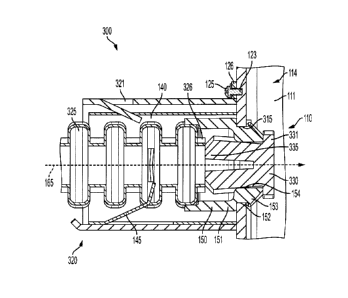
CA 3054215 2019-09-05
18CM P648CA
[0078] After forming the electrical connector 210, a portion of the
sheet 205 extending
between a first end 201 and a second end 202 provides a support bracket 206
(e.g., similar
to support bracket 160). A clip 160 can be attached to the first end 201, and
an aperture
220 can be formed at the second end 202 of the attachment 200. In some
embodiments, a
feature can be provided at the first end 201 of the attachment 200 to retain
the clip 160.
The attachment 200 can then be mechanically coupled to an electrical box
(e.g., electrical
box 110) with a fastener (not shown) interacting with the aperture 220 to
secure the
attachment 200 to the box 210 (e.g., an underneath side of the box).
[0079] FIG. 23 is a perspective view of the electrical attachment 200
of FIG. 21 and
FIG. 22 after being formed by the method of manufacturing the sheet 205
according to the
pattern 203. The electrical attachment 200 is a unitary attachment including
an electrical
connector 210 and a support bracket 206 that are integrally formed together.
FIG. 24 is an
end view of the electrical attachment 200 of FIG. 23, and FIG. 25 is a side
view of the
electrical attachment 200 of FIG. 23 showing the unitary construction of the
attachment
200 including an electrical connector 210 and a support bracket 206.
[0080] The present disclosure provides several embodiments and
features of electrical
connectors 120 fixed to the outside of an electrical box 110 that facilitate
and support a
variety of wiring configurations and electrical components. The electrical
connection
assembly 100 achieves safe and effective distribution of electric power with
the electrical
box 110 and the electrical connector 120 of the present disclosure.
[0081] FIGS. 26-28 show an alternate embodiment of an electrical
assembly 300
including alternate features for accommodating an alternate electrical
connector 320
(shown in FIG. 27 and FIG. 28). The assembly 300 is substantially the same as
the
CA 3054215 2019-09-05
18CMP648CA
assembly 100 described above with respect to FIGS 1-12, except for the
differences
discussed herein. Like reference numerals are used for like elements. As shown
in FIG.
26, the electrical box 110 includes a pair of apertures 315 oriented to
provide access into
the internal volume 114 of the housing 111.
[0082] As shown in FIG. 27, the apertures 315 are spaced apart and
configured to
accommodate a larger electrical connector 320 that is configured to
accommodate larger
cables 325. While the term "larger" is a relative term, for exemplary
purposes, the pair of
apertures 315 can be spaced apart from each other a non-standard distance to
accommodate
a larger connector than that of apertures spaced a standard distance apart
from each other.
Standard can refer to a common size manufactured in view of one or more of a
safety code
or manufacturing guideline defming the particular parameters of a feature.
Moreover, the
pair of apertures 315 is described to illustrate the versatility of an
electrical connector 320
of the present disclosure to accommodate a wide variety of shapes, sizes, and
styles of
cables. In addition to the pair of apertures 315, the electrical box 111
includes an eccentric
opening 318 positioned in a third aperture 319 on a same side 312 of the
electrical box 111
as the pair of apertures 315. Providing an eccentric opening 318 on the same
side 312 as
the pair of apertures 315 enables the electrical box 111 and connector 320 to
accommodate
a wide range of cables and electrical components.
[0083] FIG. 28 shows a cross-sectional view of the electrical
connection assembly 300
taken along line 28-28 of FIG. 27. The electrical connector 320 includes a
frame 321 with
a retainer 140 having one or more teeth 145 extending radially inward from the
frame 121
to clamp and grip the cable 325. The electrical insulating bushing 150 is
securely seated
in the aperture 315 and circumscribes the insertion path 165. As shown, the
body 151 of
26
CA 3054215 2019-09-05
18CM P648CA
the bushing 150 has a groove 152 and a flange 153 at a leading end. The groove
152 is
dimensioned to mate with the aperture 315 with the flange positioned in the
internal volume
114 of the electrical box and a trailing end of the body 151 of the bushing
150 positioned
in the retainer 140 or frame 321. Once positioned, the flange 153 and groove
152 secure
the bushing 150 in the aperture 315.
[0084] A plug 330 is positioned in an opening 154 of the electrical
bushing 150 to
obstruct the insertion path 165. The plug 330 has flange portion 331 with a
larger
dimension than the opening 154 of the bushing 150. The plug further includes a
plurality
of resilient legs 335 extending from the flange portion 331. The resilient
legs 335 are
oriented to flex in a radial direction relative to the insertion path 165. For
example, the
resilient legs 335 can be oriented to provide a structure larger than the
opening 154 that
flexes inward in a radial direction relative to the insertion path 165 when
inserted into the
opening 154. The resilient legs 335 exert a radial force to friction fit the
plug 330 within
the opening 154 of the bushing 150. A tool can be used to remove the plug 330
from the
opening 154. Alternatively, as the cable 325 is inserted along the insertion
path 165, a
leading end 326 of the cable 325 can contact the plug 330 and exert a lateral
force on the
plug 330 that causes the resilient legs 335 to flex radially inward as the end
326 of the cable
325 pushes the plug 330 the opening until the plug 330 is displaced from the
opening 154
and the insertion path 165 is not obstructed.
[0085] FIGS. 29-32 show an alternate embodiment of an electrical
assembly 400
including features substantially the same as assembly 100 and assembly 300
described
above, except for the differences discussed herein. Like reference numerals
are used for
like elements. When employed in a variety of applications, it is common to
secure the
27
CA 3054215 2019-09-05
18CM P648CA
electrical box 110 (shown in FIG. 1) to a structure. Such structures include,
but are not
limited to, studs, frames, supports, columns, braces, hardware, cabinets,
cases, walls, and
other structural members found in a variety of applications where an
electrical box 110 is
employed. The electrical assembly 400 includes one or more brackets (shown in
FIG. 29
and FIG. 30) that may be used to secure the electrical box 110 to the
structure.
[0086] Known electrical boxes and brackets may have limitations. For
example,
physical space may be limited, and the construction of the structural members
to which the
electrical box is secured may present physical constraints in terms of how and
where the
electrical box can be mounted to the structure. Additionally, bracket
geometries may limit
the number of electrical boxes that can be mounted to a structure, as well as
how and where
the electrical boxes can be mounted. Moreover, when mounting an electrical box
to a
structure, a user may encounter challenges with respect to proper placement
(e.g., height,
alignment, orientation) of the electrical box relative to the structure,
relative to other
electrical boxes, and relative to other components that may be found within a
predetermined physical space defined by the structure, such as plumbing,
insulation,
electrical wiring, and additional structural support members.
[0087] Accordingly, for safe and effective distribution of electric
power, brackets and
electrical boxes are needed that address the above-noted limitations. The
present disclosure
provides an assembly for electrical distribution including an electrical box
and a bracket
having features that can be provided either alone or in combination to
facilitate safe and
effective electrical distribution while achieving advantages that cannot be
obtained by
known electrical boxes and brackets.
28
CA 3054215 2019-09-05
18CM P648 CA
100881 FIG. 29 is a perspective view of one example of a bracket 410
of the electrical
assembly 400, and FIG. 30 is a perspective view of another example of a
bracket 510 of
the electrical assembly 400. Same or similar features between bracket 410 and
bracket 510
are identified using the same reference numerals. For simplicity and not
limitation, features
of bracket 410 will be described with the understanding that bracket 510
includes the same
or similar features, unless otherwise noted.
100891 With reference to FIG. 29, the bracket 410 includes a first
flange 411 and a
second flange 412. The first flange 411 is configured to be connected to the
electrical box
110 (shown in FIG. 1) and the second flange 412 is configured to be connected
to a
structure (shown in FIG. 31). The first flange 411 can be coupled to the
electrical box
using one or more fasteners (e.g., screw, bolt, rivet, peg, pin, adhesive,
material bonding
technique, weld).
[0090] The bracket 410 includes a corner 413 connecting the first
flange 411 with the
second flange 412. The first flange 411 extends from the corner 413 in a first
direction 421
away from the corner 413, and the second flange 412 extends from the corner
413 in a
second direction 422 away from the corner 413. The first direction 421 is
different from
the second direction 422. In the illustrated embodiment, the first direction
421 and the
second direction 422 are oriented perpendicular to each other and the corner
413 extends
linearly in a third direction 423 along the joint between the first flange 411
and the second
flange 412. The first direction 421, second direction, 422, and third
direction 423 define a
three-dimensional Cartesian coordinate system.
[0091] The bracket 410 is shown as having an inverted corner 413
configured to
receive a cover (not shown) and maintain the cover flush with the second
flange 412 and
29
CA 3054215 2019-09-05
18CM P648CA
the open face of the electrical box 110. In other embodiments, the corner 413
can be a
standard or non-inverted corner, an inverted or non-inverted rounded corner,
or corner
having other linear, non-linear, or polygonal shapes depending on the type of
cover or
particular application in which the assembly 400 is employed.
[0092] The second flange 412 includes a first edge 431, a second edge
432, and a third
edge 433 that form a continuous perimeter of the second flange 412 and define
a central
body portion 435 of the second flange 412 within the continuous perimeter and
delimited
by the corner 413. The central body portion 435 is shown as a planar surface,
although the
central body portion 435 can include non-planar surfaces in other embodiments.
The first
edge 431 and the third edge 433 intersect at a first intersection 441, and the
second edge
432 and the third edge 433 intersect at a second intersection 442.
100931 The first intersection 441 is spaced a first distance "d1" from
the corner 413,
and the second intersection 442 is spaced a second distance "d2" from the
corner 413. The
first distance "dl" does not equal the second distance "d2." In the
illustrated embodiment,
the first distance "dl" is greater than the second distance "d2," although the
second
distance "d2" can be greater than the first distance "dl" is other
embodiments.
[0094] The central body portion 435 includes a first aperture 451
positioned between
the first edge 431 and the third edge 433 and a second aperture 452 positioned
between the
second edge 432 and the third edge 433. Relative to the corner 413, the first
aperture 451
is spaced a greater distance from the corner 413 than the distance the second
aperture 452
is spaced from the corner 413. In other embodiments, where "d2" is greater
than "dl," the
second aperture 452 is spaced a greater distance from the corner 413 than the
distance the
first aperture 451 is spaced from the corner 413. Spacing the apertures 451,
452 at offset
CA 3054215 2019-09-05
18CM P648CA
locations within the central body 435 relative to the corner 413 may better
stabilize and
prevent rotation of the electrical assembly 400 than two equally spaced
apertures.
[0095] As further shown in FIG. 29, the third edge 433 includes an
inflection point
460 where the third edge 433 changes from a convex profile 461 to a concave
profile 462.
The convex profile 461 extends from the first intersection 441 to the
inflection point 460,
and the concave profile 462 extends from the second intersection 442 to the
inflection point
460. The third edge 433 defmes a continuous profile extending between the
first
intersection 441 and the second intersection 442. The inflection point 460 is
midway
between first intersection 441 and the second intersection 442, although the
inflection point
460 can be located at any location along the third edge 433 in other
embodiments without
departing from the scope of the disclosure.
[0096] Additionally, where "d2" is greater than "dl," a concave
profile can extend
from the first intersection 441 to the inflection point 460, and a convex
profile can extend
from the second intersection 442 to the inflection point 460. Alternatively,
as shown with
respect to FIG. 30, the third edge 433 can extend linearly from the first
intersection 441 to
the second intersection 442 defining a linear profile 465 oriented at a non-
parallel angle
relative to the corner 413. In other embodiments (not shown), the third edge
433 can
include one or more features including planar and non-planar profiles and one
or more
inflection points.
[0097] FIG. 31 shows a perspective view of the electrical assembly 400
including the
bracket 410 of FIG. 29 attached to the electrical box 110 of FIG. 1. Although
not shown,
it should be understood that the bracket 510 of FIG. 30 could similarly be
attached to the
electrical box 110 of FIG. 1, without departing from the scope of the
disclosure. The
31
CA 3054215 2019-09-05
18CM P648CA
assembly 400 is mounted to a structure 610 with one or more fasteners 615
(e.g., screw,
bolt, rivet, peg, pin, adhesive, material bonding technique, weld) secured
within the first
aperture 451 and the second aperture 452 (shown in FIG. 29). The structure 610
is
illustrated as a stud 610 with the understanding that the structure 610 can
include one or
more studs, frames, supports, columns, braces, hardware, cabinets, cases,
walls, or other
structural members in other embodiments.
100981 The bracket 410 and electrical box 110 are supplied to a
technician as a
completed assembly 400 with the bracket 410 fixed to the electrical box 110.
Alternatively,
the bracket 410 is provided alone or in combination with the electrical box
110 as a separate
component that a technician fastens to the electrical box 110 to provide a
completed
assembly 400. The assembly 400 is mounted to the structure 610. In some
embodiments,
a plurality of assemblies 400 can be mounted to the structure 610. For
example, in the
illustrated embodiment, two assemblies 400 are mounted to the structure 610.
The bracket
410 includes a marker 415 representing one or more of a location or position
of the bracket
410 relative to another object (e.g., another bracket, a structure 610). The
marker 415 can
be a visual marker (e.g., color, paint, sticker) or a physical marker (e.g.,
notch, scribe,
ridge).
[0099] When fastened to the electrical box 110, the first flange 411
is attached to a side
of the exterior surface 112 of the housing 111 of the electrical box 110, and
the second
flange 412 extends away from the side at a non-parallel angle relative to the
first flange
411. The first flange 411 and the second flange 412 are perpendicular to
enable mounting
of the assembly 400 on the structure 610 having a flat or planar surface
parallel to the open
face of the box 110. The second flange 412 is mounted to the structure 610
with the open
32
CA 3054215 2019-09-05
18CM P648CA
face of the box 110 parallel to the second flange 412. In other embodiments,
the structure
610 may include non-planar surfaces, or the assembly 400 may be mounted on a
structure
with the open face of the box 110 non-parallel to the second flange 412.
[0100] FIG. 32 shows an enlarged view of a portion of the assembly 400
of FIG. 31
for better clarity. Two brackets 410a, 410b are shown. For explanation
purposes, features
corresponding to bracket 410a are identified as "Xa," and features
corresponding to bracket
410b are identified as "Xb," where X corresponds to the reference numerals of
the features
described herein. As shown, when mounted side-by-side at the same elevation,
the
brackets 410a, 410b are structured to be positioned in mating relationship
relative to each
other. For example, bracket 410b is identical to bracket 410a and is oriented
or rotated
180 degrees about the inflection point 460b such that the third edge 433b of
bracket 410b
corresponds in profile to the third edge 433a of bracket 410a to provide a
complementary
mating engagement between the brackets 410a, 410b.
[0101] The third edge 433a of bracket 410a mirrors the third edge 433b
of bracket
410b . Inflection point 460a of bracket 410a is aligned with inflection point
460b of bracket
410b so that the convex profile 461a of bracket 410a mates with the concave
profile 462b
of bracket 410b, and the concave profile 462a of bracket 410a mates with the
convex
profile 461b of bracket 410b. This mating relationship between the third edge
433a of
bracket 410a and the third edge 433b of bracket 410b provides both a
structural and visual
guide to a technician mounting the assembly 400 on a structure 610.
[0102] For example, in some applications, as illustrated, it may be
desirable to mount
at least two electrical boxes side-by-side at the same elevation.
Additionally, marker 415a
of bracket 410a is aligned with marker 415b of mating bracket 410b to provide
the brackets
33
CA 3054215 2019-09-05
18CM P648CA
410a, 410b at the same height on the structure 610. The markers 415a, 415b are
shown as
scribe lines and can include other shapes such as arrows, dots, text, and
detents. The
brackets 410a, 410b of the present disclosure enable a technician to
accomplish this
objective in a reduced time and with greater accuracy and reliability than
known methods
using known brackets.
[0103] The brackets 410a, 410b are sized and shaped to enable
placement of two
brackets 410a, 410b side-by-side at the same elevation on the same structure
610. The size
and shape of the brackets 410a, 410b may be predetermined and selected based
on a
predetermined dimension of the structure 610. For example, the size and shape
of the
brackets 410a, 410b may be predetermined and selected based on the dimension
of a stud.
The brackets 410a, 410b can be manufactured from a variety of materials (e.g.,
metal,
plastic, polymeric) and can be a single, monolithic piece of material on which
a pattern can
be provided (e.g., drawn, imprinted, etched, cut, stamped, pressed, engraved)
and from
which the brackets 410a, 410b is formed (e.g., machined, manufactured, drawn,
imprinted,
etched, cut, stamped, pressed, engraved). In further embodiments, the brackets
410a, 410b
can include a plurality of sheets that are mechanical attached (e.g., welded,
bonded)
together to provide a unitary piece on which the pattern is provided and from
which the
brackets 410a, 410b are formed. A variety of features (e.g., protrusions,
recesses, cutouts,
bends, folds, seams, apertures, notches, flanges, tabs, and slots) can be
formed (e.g.,
machined, manufactured, drawn, imprinted, etched, cut, stamped, pressed,
engraved) on
the brackets 410a, 410b without departing from the scope of the disclosure.
101041 The present disclosure provides several embodiments and
features of brackets
410, 510 fixed to an electrical box 110 that facilitate and support a variety
of wiring
34
CA 3054215 2019-09-05
18CM P648CA
configurations and electrical components. The electrical assembly 400 achieves
safe and
effective distribution of electric power by mounting the electrical box 110
and the bracket
410, 510 of the present disclosure to a structure 610.
[0105] In one embodiment, an electrical connection assembly includes
an electrical
box including a housing having an internal surface defining an internal volume
of the
housing. An electrical connector is positioned outside the internal volume of
the housing
and fixed to the housing with a fastener. The housing includes an aperture
having an
opening defining an insertion path extending from a location external to the
housing along
a frame of the electrical connector to a location within the internal volume
of the housing.
The assembly includes a disc mechanically secured to the housing relative to
the opening
to obstruct the insertion path.
[0106] In another embodiment, a bushing for circumscribing an
insertion path of an
electrical connector includes a body having an opening defining a pathway
along which
the insertion path is configured to extend and a membrane. The membrane is
mechanically
coupled relative to the body to at least partially obstruct the opening.
[0107] In yet another embodiment, a method of making an electrical
connector from a
sheet of material includes severing the sheet according to a predetermined
pattern. The
method includes forming a severed segment of the sheet to provide a formed
segment
having a first opening and a second opening defining an insertion path
extending from the
first opening to the second opening along which an electrical wire is
configured to extend.
The method includes inserting a retainer within the formed segment, the
retainer at least
partially circumscribing the insertion path.
CA 3054215 2019-09-05
18CM P648CA
101081 A. An electrical connection assembly includes an electrical box
including a
housing having an internal surface defining an internal volume of the housing.
An
electrical connector is positioned outside the internal volume of the housing
and fixed to
the housing with a fastener. The housing includes an aperture having an
opening defming
an insertion path extending from a location external to the housing along a
frame of the
electrical connector to a location within the internal volume of the housing.
The assembly
includes a disc mechanically secured to the housing relative to the opening to
obstruct the
insertion path. A retainer and a bushing including a membrane for the
electrical connector
as well as methods of making an electrical connector are also provided.
101091 Cl. An electrical connection assembly comprising: an electrical
box including
a housing having an internal surface defining an internal volume of the
housing; an
electrical connector positioned outside the internal volume of the housing and
fixed to the
housing with a fastener; the housing including an aperture having an opening
defining an
insertion path extending from a location external to the housing along a frame
of the
electrical connector to a location within the internal volume of the housing;
and a disc
mechanically secured to the housing relative to the opening to obstruct the
insertion path.
[0110] C2. The electrical connection assembly of Cl, including a
retainer coupled to
the frame of the electrical connector, the retainer at least partially
circumscribing the
insertion path.
[0111] C3. The electrical connection assembly of C2, including a
bushing positioned
at least partially within the retainer and circumscribing the insertion path,
the bushing being
manufactured from an electrical insulating material.
36
CA 3054215 2019-09-05
18CM P648CA
[0112] C4. The electrical connection assembly of C3, wherein the
bushing is slidable
along the insertion path from a first end of the retainer to a second end of
the retainer.
[0113] C5. The electrical connection assembly of Cl, including a
support bracket
having a first end and a second end, wherein the second end is fixed to at
least one of the
electrical connector and the electrical box, and wherein the first end extends
cantilever
from the electrical connector in a direction away from the electrical box.
[0114] C6. The electrical connection assembly of C5, including a clip
mechanically
coupled to the first end of the support bracket.
[0115] C7. The electrical connection assembly of Cl, wherein the
electrical connector
is formed from a sheet of material.
[0116] C8. A bushing for circumscribing an insertion path of an
electrical connector,
comprising: a body having an opening defining a pathway along which the
insertion path
is configured to extend; and a membrane mechanically coupled relative to the
body to at
least partially obstruct the opening.
101171 C9. The bushing of C8, wherein the bushing is manufactured from
an electrical
insulating material.
[0118] C10. The bushing of C8, wherein the membrane is mechanically
coupled to the
body of the bushing with a frangible attachment.
[0119] C 1 1 . The bushing of C8, wherein the membrane is manufactured
from a
frangible material configured to fail upon application of a predetermined
stress less than a
stress at which a body of the bushing fails upon application.
[0120] C12. A method of making an electrical connector from a sheet of
material
comprising: severing the sheet according to a predetermined pattern; forming a
severed
37
CA 3054215 2019-09-05
18CM P648 CA
segment of the sheet to provide a formed segment having a first opening and a
second
opening defining an insertion path extending from the first opening to the
second opening
along which an electrical wire is configured to extend; and inserting a
retainer within the
formed segment, the retainer at least partially circumscribing the insertion
path.
[0121] C13. The method of C12, including mechanically coupling a clip
to a first end
of the sheet after severing the sheet according to the predetermined pattern.
[0122] C14. The method of C12, including inserting a bushing within
the retainer, the
bushing having a body including an opening defining a pathway along which the
insertion
path is configured to extend, the opening circumscribing the insertion path.
101231 C15. The method of C14, wherein the bushing is manufactured
from an
electrical insulating material.
[0124] C16. The method of C14, wherein the bushing comprises a
membrane at least
partially obstructing the opening.
[0125] C17. The method of C16, wherein the membrane is attached to the
body of the
bushing with a frangible attachment.
[0126] C18. The method of C12, wherein the formed segment is formed at
a location
of the sheet defined between a first end of the sheet and a second end of the
sheet.
[0127] C19. The method of C18, wherein the sheet includes a support
bracket
extending from the formed segment to the first end of the sheet.
[0128] C20. The method of C18, wherein the sheet includes an aperture
at a location
between the formed segment and the second end of the sheet.
[0129] To the extent that the term "includes" or "including" is used
in the specification
or the claims, it is intended to be inclusive in a manner similar to the term
"comprising" as
38
CA 3054215 2019-09-05
18CM P648CA
that term is interpreted when employed as a transitional word in a claim.
Furthermore, to
the extent that the term "or" is employed (e.g., A or B) it is intended to
mean "A or B or
both." When the applicants intend to indicate "only A or B but not both" then
the term
"only A or B but not both" will be employed. Thus, use of the term "or" herein
is the
inclusive, and not the exclusive use. See, Bryan A. Garner, A Dictionary of
Modern Legal
Usage 624 (2d. Ed. 1995). Also, to the extent that the terms "in" or "into"
are used in the
specification or the claims, it is intended to additionally mean "on" or
"onto." Furthermore,
to the extent the term "connect" is used in the specification or claims, it is
intended to mean
not only "directly connected to," but also "indirectly connected to" such as
connected
through another component or components.
101301 While
the present disclosure has been illustrated by the description of
embodiments thereof, and while the embodiments have been described in
considerable
detail, it is not the intention of the applicants to restrict or in any way
limit the scope of the
appended claims to such detail. Additional advantages and modifications will
readily
appear to those skilled in the art. Therefore, the disclosure, in its broader
aspects, is not
limited to the specific details, the representative system and method, and
illustrative
examples shown and described. Accordingly, departures may be made from such
details
without departing from the spirit or scope of the applicant's general
inventive concept.
39
CA 3054215 2019-09-05