Note: Descriptions are shown in the official language in which they were submitted.
Helium Extraction from Natural Gas
BACKGROUND
[0001] The present invention relates to processes and apparatuses for the
extraction of
helium. In particular, the invention relates to the separation of helium from
a natural gas
stream comprising methane, nitrogen, and helium using cryogenic distillation.
[0002] Helium exists in many natural gas deposits worldwide, but there is a
growing
interest in efficiently recovering helium from natural gas deposits with low
concentrations
of helium, e.g. below 2000 ppmv. Recovery of helium from natural gas at these
low
levels has long been considered uneconomical. Helium recovery from natural gas
occurs normally as a by-product of liquefied natural gas (LNG) production or
nitrogen
rejection. In both cases methane is condensed and the lighter helium is easily
recovered
as a gas. The present invention relates to the case in which the natural gas
stream does
not require liquefaction or nitrogen rejection. In this case, the gas may
still contain
significant nitrogen, but not enough to prevent the natural gas from being
used in a
pipeline or gas turbine.
[0003] Helium extraction from natural gas is known. Gottier (US5011521)
teaches
helium extraction using a stripping column to enrich the helium concentration
above the
feed gas composition. Helium enrichment is limited to the action of the
stripping column,
in the example given as roughly one order of magnitude, from 0.44% to 5.16%
helium.
The aim of enriching helium in the overhead stream is to reduce the flow to
the helium
purifier by increasing the helium molar fraction. No additional means to
enrich the
helium in the stream leaving the top of the stripping column prior to entering
the purifier
are disclosed.
[0004] Gottier also discloses the use of a dense fluid expander (DFE) to
recover
energy from expanding a higher pressure stream to a lower pressure to feed a
distillation
column. Operating the distillation column at a higher pressure incurs higher
capital costs
due to the difficulty of effecting a separation at high pressure and the
complexity of
supplying reboiler duty to the distillation column. The difficult separation
results in a
higher reboiler duty for a given helium recovery, which causes a higher vapor
flow rate.
- 1 -
CA 3054907 2019-09-10
The higher vapor flow rate coupled with unfavorable surface tension and vapor-
liquid
density ratio leads to larger column diameters. To avoid these disadvantages,
the feed
pressure is reduced prior to entering the distillation column.
[0005] Oeflke (US2014/0137599) teaches an additional separation to further
enrich the
helium content of the overhead stream from the stripping column. The overhead
stream
is cooled and reduced in pressure to form a helium-rich vapor stream and a
helium-
depleted liquid stream. The helium-depleted liquid stream, which still
contains some
helium, is pumped and combined with the helium-depleted natural gas from the
bottom
of the stripping column. The helium not recovered from the helium-depleted
liquid
stream reduces overall recovery by 0.4% according to the example given.
Furthermore,
the pressure of the helium-rich vapor stream is reduced from 550 psia to 100
psia in the
example which may require recompression to enter the downstream helium
purification
step.
[0006] Mitchell et al (US4758258) teach a multistage separation for recovery
of helium
from natural gas along with separation of ethane, propane, and heavier
hydrocarbons
from the bulk methane. It is similar to Oeflke in two respects. First, the
refrigeration for
the final separation of helium and nitrogen from methane is achieved by
reducing the
pressure of the feed to the separator to produce a crude helium stream.
Second, the
helium contained in the liquid stream from the separator is not recovered,
reducing the
overall helium recovery.
[0007] Agrawal (US5167125) teaches a process where light gases, such as
helium,
are removed by partially condensing the overhead vapor from a distillation
column. The
liquid stream formed provides reflux to the distillation column and the helium-
enriched
vapor stream can be further purified.
[0008] In order to minimize the power required in helium extraction processes
described in the prior art, intermediate streams that contain small but
significant amounts
of helium are rejected to the helium-depleted natural gas product, lowering
overall helium
recovery. There is a need for achieving the highest possible overall helium
recovery by
recovering helium from intermediate streams in a power-efficient manner.
- 2 -
CA 3054907 2019-09-10
SUMMARY
[0009] This invention relates to a multi-step process to extract helium from a
natural gas
stream optimized for high helium recovery and low power consumption. First,
contaminants are removed as needed, for example CO2 by amine absorption, water
and
heavy hydrocarbons by temperature swing adsorption, and/or mercury by
adsorption on
activated carbon. Next helium is extracted using a cryogenic distillation
column system.
The helium content in the column overhead stream is enhanced with a condenser
to
recover nitrogen and methane, both increasing methane recovery and reducing
the flow
rate to downstream helium purification. The crude helium stream passes to a
cryogenic
partial condensation process to further increase the helium concentration
before hydrogen
is removed by catalytic combustion. Final purification is by pressure swing
adsorption
(PSA), from which the tail gas is recompressed, dried and recycled. The pure
helium
product from the PSA can then be liquefied for transport and sale.
[0010] The helium-depleted liquid from the bottom of the distillation column
system is
used to provide refrigeration to the process. Multiple pressures are chosen
for the
refrigerant to optimize the cooling curves and thus the efficiency of heat
transfer. Some
of the helium-depleted liquid is pumped to minimise overall recompression
power. All of
the returning natural gas streams are recompressed to match the feed pressure
if returning
to a pipeline, or are recompressed to whatever pressure is required for
utilization of the
natural gas, e.g. combustion in a gas turbine.
[0011] The pressure of the distillation column system is selected to reduce
the risk of
poor separation resulting from operating at too high of a pressure. To
mitigate the
increased power demand, a dense fluid expander (DFE) can be used to generate
power
that can be used in the process by expanding the feed stream to column
pressure.
Expanding the fluid isentropically through a DFE also produces a lower
temperature in the
outlet stream than would be produced by expanding isenthalpically though a
valve. Using
a DFE saves power for an increased capital cost, and must be optimized
accordingly. The
process can also utilize an expander on one or more of the returning streams
to reduce
overall net power consumption and provide refrigeration to the process.
- 3 -
CA 3054907 2019-09-10
BRIEF DESCRIPTION OF THE DRAWINGS
[0012] The present invention will hereinafter be described in conjunction with
the
appended figures wherein like numerals denote like elements:
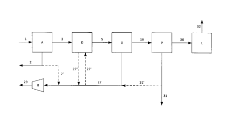
[0013] FIG. 1 is a flowsheet depicting a process for the pretreatment,
extraction,
purification, and liquefaction of helium from a natural gas stream.
[0014] FIG. 2 is a flowsheet depicting the helium extraction process according
to the
present invention.
DETAILED DESCRIPTION
[0015] The ensuing detailed description provides preferred exemplary
embodiments
only, and is not intended to limit the scope, applicability, or configuration
of the invention.
Rather, the ensuing detailed description of the preferred exemplary
embodiments will
provide those skilled in the art with an enabling description for implementing
the preferred
exemplary embodiments of the invention. Various changes may be made in the
function
and arrangement of elements without departing from the spirit and scope of the
invention,
as set forth in the appended claims.
[0016] The articles "a" or "an" as used herein mean one or more when applied
to any
feature in embodiments of the present invention described in the specification
and
claims. The use of "a" and "an" does not limit the meaning to a single feature
unless
such a limit is specifically stated. The article "the" preceding singular or
plural nouns or
noun phrases denotes a particular specified feature or particular specified
features and
may have a singular or plural connotation depending upon the context in which
it is used.
[0017] The term "and/or" placed between a first entity and a second entity
includes any
of the meanings of (1) only the first entity, (2) only the second entity, and
(3) the first
entity and the second entity. The term "and/or" placed between the last two
entities of a
list of 3 or more entities means at least one of the entities in the list
including any specific
combination of entities in this list. For example, "A, B and/or C" has the
same meaning
as "A and/or B and/or C" and comprises the following combinations of A, B and
C: (1)
only A, (2) only B, (3) only C, (4) A and B and not C, (5) A and C and not B,
(6) B and C
and not A, and (7) A and B and C.
[0018] The term "plurality" means "two or more than two."
- 4 -
CA 3054907 2019-09-10
[0019] The adjective "any" means one, some, or all, indiscriminately of
quantity.
[0020] The phrase "at least a portion" means "a portion or all." The "at least
a portion of
a stream" has the same composition, with the same concentration of each of the
species, as the stream from which it is derived.
[0021] As used herein, "first," "second," "third," etc. are used to
distinguish among a
plurality of steps and/or features, and is not indicative of the total number,
or relative
position in time and/or space, unless expressly stated as such.
[0022] All composition values will be specified in mole percent.
[0023] The terms "depleted" or "lean" mean having a lesser mole percent
concentration
of the indicated component than the original stream from which it was formed.
"Depleted"
and "lean" do not mean that the stream is completely lacking the indicated
component.
[0024] The terms "rich" or "enriched" mean having a greater mole percent
concentration of the indicated component than the original stream from which
it was
formed.
[0025] "Downstream" and "upstream" refer to the intended flow direction of the
process
fluid transferred. If the intended flow direction of the process fluid is from
the first device
to the second device, the second device is downstream of the first device. In
case of a
recycle stream, downstream and upstream refer to the first pass of the process
fluid.
[0026] The term "dense fluid expander," abbreviated DFE, also known as a
liquid
expander, refers to equipment that extracts mechanical work from lowering the
pressure
of a dense fluid such as a liquid or a supercritical fluid, similar in
function to an expander
for gases. This expansion is best approximated as an isentropic process, as
opposed to
a valve which is best approximated as an isenthalpic process.
[0027] The term "indirect heat exchange" refers to the process of transferring
sensible
heat and/or latent heat between two or more fluids without the fluids in
question coming
into physical contact with one another. The heat may be transferred through
the wall of a
heat exchanger or with the use of an intermediate heat transfer fluid. The
term "hot stream"
refers to any stream that exits the heat exchanger at a lower temperature than
it entered.
Conversely, a "cold stream" is one that exits the heat exchanger at a higher
temperature
than it entered.
- 5 -
CA 3054907 2019-09-10
[0028] The term "distillation column" includes fractionating columns,
rectifying columns,
and stripping columns. The distillation column may refer to a single column or
a plurality
of columns in series or parallel, where the plurality can be any combination
of the above
column types. Each column may comprise one or more sections of trays and/or
packing.
[0029] The term "reboiling" refers to partially vaporizing a liquid present in
the distillation
column, typically by indirect heat exchange against a warmer process stream.
This
produces a vapor that facilitates mass transfer within the distillation
column. The liquid
may originate in the bottoms liquid or an intermediate stage in the column.
The heat duty
for reboiling may be transferred in the distillation column using an in situ
reboiler or
externally in a heat exchanger dedicated for the purpose or part of a larger
heat exchanger
system. The vapor-liquid separation also may take place within the
distillation column or
within an external flash vessel.
[0030] The present apparatus and process are described with reference to the
figures.
In this disclosure, a single reference number may be used to identify a
process gas
stream and the process gas transfer line that carries said process gas stream.
Which
feature the reference number refers to will be understood depending on the
context.
[0031] For the purposes of simplicity and clarity, detailed descriptions of
well-known
devices, circuits, and methods are omitted so as not to obscure the
description of the
present invention with unnecessary detail.
[0032] The natural gas feed described in the present invention refers to a gas
comprising
hydrocarbons, usually originating underground in a geological formation. The
natural gas
is typically produced at a pressure ranging from about 1 to about 200 bar. All
pressures
referred to are absolute, not gauge. The pressure of the natural gas is
preferably from
about 10 to about 100 bar.
[0033] The methane content in natural gas typically ranges from about 50% to
about
99%. All composition percentages referred to are in volume, or molar, basis,
not weight
basis.
[0034] The nitrogen content in natural gas typically ranges from about 1% to
about 50%,
or from about 10% to about 35%.
[0035] The helium content in natural gas typically ranges from about 0.01% to
about
10%. Some embodiments of the present invention are directed to extracting
helium from
- 6 -
CA 3054907 2019-09-10
natural gas comprising from about 0.05% to about 1.0%, or from about 0.05% to
about
0.2% helium.
[0036] Figure 1 shows the overall process of helium production from a natural
gas
source. The raw natural gas 1 enters acid gas removal unit A as needed for
removal of
gases such as CO2, H2S and COS that would freeze in the downstream cryogenic
units.
The acid gases in stream 2 can be vented to the atmosphere or sent to sulfur
removal as
needed. There are several options for acid gas removal, including pressure
swing
adsorption, vacuum swing adsorption, or methanol absorption, which in the
following
examples presented herein is assumed to be an amine absorber regenerated with
steam.
[0037] The contaminant-lean natural gas leaving A in stream 3 now contains an
acceptably low level of acid gases, typically at a specification of less than
about 100 ppmv.
If an amine absorber is used, stream 3 will be saturated in water vapor that
would solidify
in the downstream cryogenic process. Stream 3 would therefore feed dehydration
unit D
which preferably comprises a temperature swing adsorber (TSA) and a mercury
guard bed
comprising activated carbon, both well-known in the art for water and mercury
removal,
respectively. The TSA removes water, CO2, and aromatics such as benzene,
toluene, and
xylene (collectively known as BTX). Specifications are set to prevent the
formation of a
solid phase in the cryogenic process; for example the water specification is
often about 1
ppmv.
[0038] The impurities are adsorbed and then removed when the TSA is
regenerated.
Regeneration requires both heat, which can be provided by electrical heaters
or process
steam, and a process stream to carry the impurities out of the TSA, such as
nitrogen or a
portion of a helium-depleted stream from the helium extraction unit X.
Depending on the
pressure required to regenerate the TSA, that stream may be at least a portion
of a low-
pressure return stream 27 or the helium-depleted natural gas stream 29. Shown
in Figure
1 is the case where a low-pressure stream may be used, in which case stream
27' is used
as the regeneration gas. The impurity-laden natural gas stream 27" can then be
recombined with the remainder of stream 27 prior to recompression. If nitrogen
is used to
regenerate the TSA, the impurity-laden nitrogen gas may be vented to the
atmosphere or
sent to further treatment to remove the hydrocarbons as determined by air
pollution
regulations. When vapor-phase mercury is present in the feed stream, a mercury
guard
bed is required with the TSA to prevent the vapor-phase mercury from attacking
the
aluminum in the downstream heat exchangers.
- 7 -
CA 3054907 2019-09-10
[0039] The natural gas feed stream 5 enters the helium extraction unit X,
which is the
subject of the present invention. The helium extraction unit is a cryogenic
process that
separates at least 99% of the helium, or at least 99.5% of the helium from the
natural
gas feed stream, which can contain from 0.05% to 1.0% helium by volume, or
from
0.05% to 0.2% helium by volume, to create a crude helium stream, which can
contain 4
to 20% helium by volume. The cryogenic process is designed for maximum
efficiency at
this high helium recovery rate that requires careful heat integration to
reduce the overall
power requirements of the process.
[0040] The low-pressure return stream 27 is recompressed in compressor R if
needed
to be returned to the pipeline, combusted in a gas turbine, or otherwise
utilized as
helium-depleted natural gas 29. The low pressure return stream may leave the
extraction unit as one or more streams at different pressures. For an example,
see
streams 27 and 28 in Figure 2. Higher pressure streams may enter a later stage
of
compression or bypass compression entirely and be combined with the helium-
depleted
natural gas.
[0041] Crude helium stream 16 is sent to helium purification unit P to produce
a pure
helium stream 30 with a typical specification of 99.99% or 99.999%. Within the
helium
purification unit (and therefore not shown in Figure 1) stream 16 is cooled to
cryogenic
temperatures, partially condensing the feed stream so that most of the
nitrogen and
virtually all the methane condenses, leaving a vapor stream with a composition
of about
50 to 90% helium, or about 70 to 85% helium, and usually about 80% helium.
This vapor
stream is warmed and then the hydrogen is removed by a catalytic combustion
process
before it is fed to a helium PSA. The liquid stream leaving the partial
condensation
process is reduced in pressure to recover helium by flashing and withdrawing a
vapor
= 25 stream. The vapor stream is warmed, recompressed, and
combined with the crude
helium stream entering the purifier. Having decreased the pressure of the
liquid stream,
the resulting lower-temperature liquid stream provides refrigeration to the
partial
condensation process. This small stream 31 leaves the helium purification
process and
can be recompressed into the sales gas stream as stream 31' or vented to
atmosphere
as stream 31 after passing through a catalytic combustion process to remove
the
methane if needed. The tail gas from the helium PSA is dried by a TSA to
remove the
water produced by the catalytic combustion of hydrogen with air or a stream
enriched in
oxygen, then is recompressed and mixed with stream 16 as it enters the
purifier. Also
- 8 -
CA 3054907 2019-09-10
recycled to the feed to the purifier is the helium collected in the "gas bag",
to minimize
the overall losses of helium from the process.
[0042] Alternate embodiments of the helium purification unit are well known in
the art.
Blackwell and Kalman (US 3,599,438) describe helium purification in more
detail,
including the steps of hydrogen removal by catalytic oxidation, dehydration by
adsorption, and helium enrichment by partial condensation. Blackwell and
Kalman also
show the recycle of the intermediate pressure helium stream (16). Kirk-Othmer
Encyclopedia of Chemical Technology, "Cryogenic technology," (2012) also
describes
alternative helium purification arrangements. For example, Figure 13 in that
chapter
shows a process with a single pressure flash in the helium cold end that
causes a higher
helium loss due to helium dissolved in the liquid stream leaving the system.
Figure 14 in
the same chapter shows a different order of operations: partial condensation
first,
followed by catalytic oxidation and final purification by PSA, where the PSA
tail gas is
recompressed, dehydrated, and recycled to the partial condensation step.
Gottier and
Herron (US 5,017,204) describe a helium purification cycle employing a
dephlegmator
that combines heat transfer and mass transfer steps into a single heat
exchanger. Any
of these methods, or similar purification methods, may be employed to generate
a pure
helium product from a crude helium stream.
[0043] The pure helium stream 30 can be sold as a gaseous product, but more
commonly it is liquefied in helium liquefier L to produce a liquid helium
stream 32 that
can be transported long distances more efficiently. The liquefier also removes
traces of
neon if present. The liquefier may use liquid nitrogen for refrigeration at
the warm end of
the process, provided by a small nitrogen generator or imported by truck as
liquid, or it
may use any other refrigeration option known in the art. The cold end of the
process
typically uses recycled helium in a heat pump arrangement for refrigeration.
[0044] If desired, at least a portion of the acid gas stream 2' and/or the
tail gas 31' can
be mixed with the helium-depleted natural gas 29 prior to recompression or at
an
interstage in the recompression. This can be advantageous if the helium-
depleted
natural gas was designed for a given mass flow rate, such as for a gas
turbine. If there
is a small amount of H2S present in the acid gas stream, then recompression
and dilution
may avoid the complications of venting H2S-containing CO2, or the expense of
oxidizing
the H2S, or the cost of a tall vent stack. Similarly, recompression of stream
31' can avoid
- 9 -
CA 3054907 2019-09-10
the added cost of oxidizing the remaining methane in the tail gas stream if
needed prior
to venting.
[0045] Figure 2 shows the helium extraction unit X in detail. The natural gas
feed
stream 5 is fed to a heat exchanger 101, after leaving the pretreatment units
A and D in
Figure 1. The heat exchanger is typically a brazed aluminium plate-fin heat
exchanger,
common to the cryogenic industry, and can be configured as one or more heat
exchangers in series or parallel. The stream is cooled in the heat exchanger
against
streams returning from the cryogenic distillation section, at least partially
condensed, and
exits the heat exchanger as cooled natural gas feed 6. If needed, the pressure
of stream
6 may be reduced in order to achieve a good separation in the distillation
column. The
parameter for achieving good separation may be the ratio of liquid phase
density to
vapor phase density, where the desired ratio is greater than 4, or greater
than 6, or
greater than 8. The parameter may also be the liquid phase surface tension,
where the
desired value is greater than 0.5 dyne/cm, or greater than 1 dyne/cm, or
greater than 2
dyne/cm. If pressure reduction is required, it is shown in Figure 2 as
occurring in valve
102, but can also be achieved by a dense fluid expander. The column feed
stream 7
then enters distillation column 103, preferably at the top stage.
[0046] The distillation column 103 separates the helium from the column feed
stream 7,
which leaves the top of the column as helium-enriched overhead vapor 8. The
distillation
column requires a reboiler, which is shown in Figure 2 as an external
reboiler. In this
configuration liquid stream 9 leaves the bottom of the column and then is
heated indirectly
by the natural gas feed 5 in the heat exchanger 101. The partially vaporized
stream 10 is
then separated in a reboiler separator 104. The distillation column 103, the
reboiler
separator 104, and the portion of heat exchanger 101 used for transferring
heat to stream
9 compose the distillation column system. Vapor stream 11 is returned to the
distillation
column 103 and helium-depleted bottoms liquid exits the distillation column
system as
stream 12.
[0047] The distillation column system is shown in Figure 2 with an external
reboiler
arrangement, where 104 is the reboiler separator. The reboiler can also be
internal to the
column, or the external reboiler can be a separate heat exchanger rather than
integrated
into a multiple-stream heat exchanger with other hot and cold streams as shown
as 101 in
Figure 2. The reboiler provides vapor feed to the bottom of the column by
boiling part of
the liquid leaving the bottom of the column as stream 9. As known in the art,
this can be
- 10 -
CA 3054907 2019-09-10
done in several ways. A reboiler, such as a thermosyphon reboiler, could sit
in the liquid
sump to boil liquid within the sump. In that case a stream with a temperature
between that
of streams 5 and 6 would be fed to the reboiler to provide the required heat
and the liquid
stream leaving the column sump would have the same conditions as stream 12 in
Figure
2. The distillation column system can employ one of the reboiler
configurations described
above or any other known reboiler.
[0048] The helium-enriched overhead vapor 8 is then partially condensed in
heat
exchanger 105. The partially condensed overhead 13 enters overhead separator
106.
This overhead separator 106 may be a simple flash vessel or a distillation
column with
multiple stages. The overhead from 106 is the crude helium vapor stream 14.
The crude
helium vapor stream 14 provides refrigeration by traveling through both heat
exchangers
105 and 101 before leaving the helium extraction unit as stream 16. This crude
helium
vapor 14 is now at a high enough concentration, typically 4% to 20% by volume,
to enter
a helium purifier, shown as unit P in Figure 1.
[0049] The recycle liquid stream 17 exits the bottom of overhead separator 106
and is
returned to the distillation column 103. Although stream 17 appears in the
same location
in the flow sheet as would a reflux stream for a conventional distillation
process, the recycle
liquid in the present invention is unsuitable for providing reflux for two
reasons. First, the
flow of stream 17 is small compared to the flow in the column feed 7, unlike a
reflux stream
that must have a liquid flow rate high enough to wash the vapor flowing up the
column.
Because the recycle liquid stream 17 has a relatively small flow rate, it does
not affect the
separation and is only returned to the distillation column to recover the
helium contained
in stream 17. Second, the distillation column 103 operates as a stripping
column with the
column feed entering at the top stage. The recycle liquid 17 can enter at the
top stage or
any lower stage, so it does not have the opportunity to wash the vapor leaving
the top
stage.
[0050] The pressure in the overhead separator 106 must be kept as close as
possible
to the pressure of the distillation column system such that the liquid head
pressure in
stream 17 is sufficient to overcome the pressure drop and flow into the
distillation column
103. This lowers the overall power consumption of the process because the
crude
helium vapor stream from the overhead separator 106 thus requires no
recompression.
Note that the higher pressure in the overhead separator results in more helium
being
- 11 -
CA 3054907 2019-09-10
trapped in the stream 17, but this liquid-phase helium is recovered by
recycling stream
17 back to the distillation column 103.
[0051] The helium-depleted bottoms liquid 12 may be split into at least two
streams,
each of which provides cooling at a different pressure and so different
temperature.
Stream 12 may be split into up to as many streams as one more than the number
of stages
of compression available in the recompressor R. This is because each stage of
compression can accept one stream at its suction pressure, and one additional
stream
may bypass R if it is at the same pressure as the outlet of R. In the
embodiment shown in
Figure 2, stream 12 is split into three streams: 18, 21, and 23. Using the
product streams
to refrigerate the process is known as auto-refrigeration, and improves
efficiency
compared to external refrigeration. Using multiple pressure levels of the
returning process
streams minimizes the temperature differences throughout the heat exchanger
system,
improving efficiency and resulting in a lower overall recompression power
requirements.
The first helium-depleted bottoms fraction 18 is reduced in pressure to
produce stream 19.
The pressure reduction is shown as valve 105 but could also be achieved with a
DFE.
Stream 19 provides the refrigeration to partially condense stream 8 in heat
exchanger 105,
after which stream 20 provides more refrigeration to heat exchanger 101. The
second
helium-depleted bottoms fraction 21 may be reduced in pressure to produce
stream 22 if
needed for additional refrigeration. If required, the pressure reduction could
be effected in
valve 107 or with a DFE. Stream 22 provides refrigeration to heat exchanger
101. Because
it is let down to an intermediate pressure greater than the pressure of stream
19, the
temperature of stream 22 is not as cold as stream 19. The third helium-
depleted bottoms
fraction 23 can be increased in pressure in pump 108 to produce stream 24.
Stream 24
then provides refrigeration by being vaporized in heat exchanger 101. Pumping
a liquid
stream before vaporizing it, as shown herein, is more efficient than
vaporizing a liquid
stream and then compressing the vapor because liquids are effectively
incompressible.
[0052] After stream 22 is warmed in heat exchanger 101, the resulting warmed
second
helium-depleted bottoms fraction 25 may be expanded in expander 109, if
desired, which
both cools the stream and generates power. The resulting expanded second
helium-
depleted bottoms fraction 26 can be returned to heat exchanger 101 to provide
more
cooling, then be combined with stream 20, and finally exit the heat exchanger
as low-
pressure return stream 27. Stream 27 is then recompressed in return compressor
R.
Stream 24 exits the heat exchanger 101 as medium-pressure return stream 28,
which can
be recompressed by feeding an interstage of return compressor R. Depending on
the
- 12 -
CA 3054907 2019-09-10
pressure required in the final helium-depleted natural gas product, pump 108
could
increase the pressure of stream 23 to a high enough level that no further
compression is
needed.
[0053] Heat exchangers 101 and 105 represent a heat exchanger system, which in
various embodiments of the invention may be a single heat exchanger or be
split into two
or more heat exchangers in series or parallel. For instance, the heat
exchanger 101 may
be divided into two separate heat exchangers at the point the expanded second
helium-
depleted bottoms fraction 26 is returned to the exchanger and mixed with
stream 20 as it
returns from 105. It may also be that the duty required for the reboiler is
provided by a
separate heat exchanger either in parallel with 101 or at the cold end of 101,
exchanging
heat solely between stream 6 and stream 9 to simplify the operation of the
distillation
column system. In general, the more integrated the heat exchanger system is,
the more
efficient the heat exchange is between all of the desired streams. However,
the heat
exchanger is often divided, which sacrifices efficiency, because a small
increase in
overall power consumption allows an advantage such as simplified operation, a
smaller
heat exchanger system, a simpler design of the heat exchanger system, or the
reduction
of risk to the process.
[0054] Return compressor R can be a single compressor with one or more stages,
with
or without intercoolers between stages, or a plurality of compressors in
series or parallel.
In the series arrangement, stream 27 could enter the first of the compressors
and stream
28 could enter a compressor further along the series. In a parallel
arrangement, separate
compressors could compress streams 27 and 28 to the desired final discharge
pressure.
The recompressed gas exits the helium extraction unit as helium-depleted
natural gas
stream 29, which can then be fed to a pipeline, combusted, or otherwise
utilized. If waste
streams 2' and/or 31' are to be recompressed and combined with the helium-
depleted
natural gas stream, they are also fed to R.
[0055] There are situations where recompression of the medium-pressure return
stream
may not be required. The pressures of the return streams 20, 22, and 24 must
all be less
than the pressure of feed stream 5 because the return streams must boil at a
pressure
lower than the feed stream condenses at to allow efficient operation of heat
exchanger
101. If the desired pressure of stream 29 is less than the pressure of stream
5, then stream
24 may be pumped to a pressure equal to that of stream 29 and not need further
- 13 -
CA 3054907 2019-09-10
compression. In that case, the medium-pressure return stream 28' may instead
bypass
the return compressor and be mixed directly with stream 29.
[0056] Certain embodiments and features of the invention have been described
using a
set of numerical upper limits and a set of numerical lower limits. For the
sake of brevity,
only certain ranges are explicitly disclosed herein. However, it should be
appreciated that
ranges from any lower limit to any upper limit are contemplated unless
otherwise
indicated. Similarly, ranges from any lower limit may be combined with any
other lower
limit to recite a range not explicitly recited, and ranges from any upper
limit may be
combined with any other upper limit to recite a range not explicitly recited.
Further, a
range includes every point or individual value between its end points even
though not
explicitly recited. Thus, every point or individual value may serve as its own
lower or
upper limit combined with any other point or individual value or any other
lower or upper
limit, to recite a range not explicitly recited. All numerical values are
"about" or
"approximately" the indicated value, and take into account experimental error
and
variations that would be expected by a person having ordinary skill in the
art.
[0057] Aspects of the present invention include:
#1: A process for recovering helium from a natural gas feed comprising
methane,
nitrogen, and helium, said process comprising:
cooling said natural gas feed to produce a cooled natural gas feed which is at
least
partially condensed;
separating the cooled natural gas feed in a distillation column system to
produce a
helium-enriched overhead vapor and a helium-depleted bottoms liquid;
cooling said helium-enriched overhead vapor to produce a partially condensed
overhead
stream;
separating said partially condensed overhead stream in an overhead separator
to
produce a crude helium vapor and a recycle liquid;
expanding at least a portion of the helium-depleted bottoms liquid to produce
a first
helium-depleted bottoms fraction;
wherein cooling duty for cooling said helium-enriched overhead vapor is
provided at least
in part by indirect heat exchange with said first helium-depleted bottoms
fraction.
- 14 -
CA 3054907 2019-09-10
#2. A process according to #1 wherein the pressure of said cooled natural gas
feed is
reduced to achieve a ratio of liquid to vapor density in the distillation
column greater than
4.
#3. A process according to any of #1 to #2 wherein the pressure of said cooled
natural
gas feed is reduced to achieve a liquid phase surface tension in the
distillation column
greater than 0.5 dyne/cm.
#4. A process according to any of #1 to #3 wherein the difference between the
pressure
of the top of the distillation column system and the pressure of said overhead
separator
is no more than 1 bar.
#5. A process according to any of #1 to #4 wherein the re-boiling duty for
said distillation
column system is provided at least in part by indirect heat exchange with the
natural gas
feed.
#6. A process according to any of #1 to #5 wherein said recycle liquid is
introduced to
the distillation column.
#7. A process according to #6 wherein the recycle liquid is introduced to the
distillation
column at the same or lower stage as the location where the cooled natural gas
is fed to
the distillation column.
#8. A process according to any of #1 to #7 further comprising the step of
expanding at
least a portion of said helium-depleted bottoms liquid to produce a second
helium-
depleted bottoms fraction.
#9. A process according to #8 wherein the pressure of said second helium-
depleted
bottoms fraction is higher than the pressure of said first helium-depleted
bottoms
fraction.
#10. A process according to any of #8 to #9 further comprising the steps of
warming said
second helium-depleted bottoms fraction to provide at least a portion of the
refrigeration
to cool and condense said natural gas feed and produce a warmed second helium-
depleted bottoms fraction;
and expanding said warmed second helium-depleted bottoms fraction to provide
power
and produce an expanded second helium-depleted bottoms fraction.
- 15 -
CA 3054907 2019-09-10
#11. A process according to any of #8 to #10 further comprising combining and
compressing said first and second helium-depleted bottoms fractions, or
streams derived
therefrom, to produce a helium-depleted natural gas stream.
#12. A process according to any of #8 to #11 further comprising the steps of
pressurizing
at least a portion of said helium-depleted bottoms liquid to produce a third
helium-
depleted bottoms fraction;
and warming said third helium-depleted bottoms fraction to provide at least a
portion of
the refrigeration to cool and condense said natural gas feed.
#13. A process according to #12 further comprising combining and compressing
said
first, second, and third helium-depleted bottoms fraction, or streams derived
therefrom,
to produce a helium-depleted natural gas stream.
#14. A natural gas processing plant for recovering helium from a natural gas
feed
comprising methane, nitrogen, and helium, said plant comprising:
a heat exchanger system;
a distillation column system comprising a vapor outlet and a liquid outlet;
a first conduit for transferring a cooled natural gas feed from said heat
exchanger system
to said distillation column;
a second conduit for transferring a helium-enriched overhead vapor from said
vapor
outlet of said distillation column to said heat exchanger system;
an overhead separator comprising a vapor outlet and a liquid outlet;
a third conduit for transferring a partially condensed overhead from said heat
exchanger
system to said overhead separator;
a fourth conduit for transferring a first helium-depleted bottoms fraction
from said liquid
outlet of said distillation system to said heat exchanger system;
Wherein said fourth conduit comprises a pressure reduction device.
#15. A natural gas processing plant according to #14 wherein said first
conduit
comprises a pressure reduction device.
#16. A natural gas processing plant according to any of #14 to #15 further
comprising a
fifth conduit for transferring a recycle liquid from said liquid outlet of
said overhead
separator to said distillation column.
- 16 -
CA 3054907 2019-09-10
#17. A natural gas processing plant according to #16 wherein said fifth
conduit connects
to said distillation column at the same stage as or a lower stage than where
said first
conduit connects to said distillation column.
#18. A natural gas processing plant according to any of #14 to #17 further
comprising a
sixth conduit for transferring a second helium-depleted bottoms fraction from
said liquid
outlet of said distillation system to said heat exchanger system, wherein said
sixth
conduit further comprises a pressure reduction device.
#19. A natural gas processing plant according to #18 further comprising:
an expander;
a seventh conduit for transferring a warmed second helium-depleted bottoms
fraction
from said heat exchanger to said expander;
and an eighth conduit for transferring an expanded second helium-depleted
bottoms
fraction from said expander to said heat exchanger system.
#20. A natural gas processing plant according to any of #18 to #19 further
comprising:
a pump;
a ninth conduit for transferring a third helium-depleted bottoms fraction from
said liquid
outlet of said distillation system to said pump;
and a tenth conduit for transferring a pressurized third helium-depleted
bottoms fraction
from said pump to said heat exchanger system.
#21. A natural gas processing plant according to any of #18 to #20 further
comprising:
a return compressor;
and an eleventh conduit for transferring a low-pressure return stream from
said heat
exchanger system to said return compressor.
#22. A natural gas processing plant according to #21 further comprising a
twelfth conduit
for transferring a medium-pressure return stream from said heat exchanger
system to
said return compressor.
#23. A natural gas processing plant according to #21 further comprising:
a mixing device;
- 17 -
CA 3054907 2019-09-10
a thirteenth conduit for transferring a compressed helium-depleted natural gas
stream
from said return compressor to said mixing device;
and a fourteenth conduit for transferring a medium-pressure return stream from
said heat
exchanger system to said mixing device.
EXAMPLE 1
[0058] A computer simulation of the process of Figures 1 and 2 was carried out
in Aspen
Plus, a commercially available process simulation software package. The feed
stream of
natural gas contains 35% nitrogen and 0.14% helium. Key stream parameters such
as
composition, pressure, temperature, and flow rate, are shown in Table 1, along
with total
power consumption.
[0059] For purposes of Example 1, two changes were made to the process
depicted in
Figures 1 and 2. This example assumes that steam 31' of Figure 1 is
recompressed with
the helium-depleted natural gas stream, but stream 2 is vented to atmosphere.
This
example also assumes that stream 5 of Figure 2 is cooled, condensed, and
expanded
across a DFE in place of valve 102.
[0060] As shown in Table 1, the helium extraction unit X produces a crude
helium stream
16 with greater than 12% helium, rich enough to feed the helium purification
unit P, while
maintaining 99.9% recovery in the helium extraction unit. Recovery in unit X
is defined as
the helium contained in stream 16 leaving the unit divided by the helium
contained in
stream 5 entering the unit. This high recovery is possible because recycle
liquid stream
17, which holds 6.8% of the helium contained in the helium-enriched condensed
overhead
stream 12, is returned to the distillation column. In known processes that
further
concentrate the distillation column overhead, that liquid-phase helium would
be lost
because the equivalent of stream 17 would be routed to the equivalent of
helium-depleted
natural gas stream 29. The 99.9% helium recovery in the helium extraction unit
X allows
an overall helium recovery of 99.6% due the small loss of helium in stream
31', where the
overall helium recovery is defined as the helium contained in pure helium
stream 30
divided by the helium contained in raw natural gas stream 1.
[0061] This process provides flexibility over the crude helium stream 16
composition.
The helium mole fraction of stream 16 can be increased by either increasing
the flow rate
or decreasing the pressure of the low pressure return stream 19. Either option
results in
- 18 -
CA 3054907 2019-09-10
a higher concentration of helium in stream 16 at the cost of an increased
power
requirement to compress stream 27.
[0062] If the waste stream from the helium purification process were to be
vented as
stream 31, an optimization that minimizes power would increase the flow rate
of methane
in stream 16 to avoid recompression in compressor R. The optimization would
need to
include the the value of methane in the vent 31 to balance the increase in
stream 16.
Table 1
Stream
1 2 5 8 12 14 17 19
Component Composition
He mol% 0.14 0.00 0.15 2.81 0.00 12.80
0.24 0.00
N2 MOP/0 35.09 0.00 36.74 75.26 36.22
81.45 73.67 36.22
CO2 mol% 4.01 88.79 0.00 0.00 0.00 0.00
0.00 0.00
CH4 mol% 60.16 0.00 62.99 21.78 63.65
5.17 26.05 63.65
C2H6 mol% 0.10 0.00 0.10 0.00 0.11 0.00
0.00 0.11
C3H8 mol% , 0.01 0.00 0.01 0.00 0.01 0.00
0.00 0.01
H20 mol% 0.47 11,14 0.00 0.00 0.00 0.00
0.00 0.00
H2 MOF/0 0.01 0.00 0.01 0.15 0.00 0.58
0.04 0.00
Temperature C 67.2 58.9 26.7 -140.6 -139.3
-155.9 -155.9 -160.1
Pressure bar (abs) 39.3 1.7 37.6 , 19.7 19.8
19.7 19.7 5.5
Flowrate (total) kmol/hr 22679.6 1024.4 21662.9 1212.6
21415.0 247.8 964.7 1054.3
Stream
22 24 25 26 31 29 16 30
Component Composition
He mol% 0.00 0.00 0.00 0.00 0.01 0.00
12.80 100.00
N2 mol% 36.22 36.22 36.22 36.22 94.06
36.81 81.45 0.00
CO2 mol% 0.00 0.00 0.00 0.00 0.00 0.00
0.00 0.00
CH4 mol% 63.65 63.65 63.65 63.65 5.90
63.07 5.17 0.00
C2H6 mol% 0.11 0.11 0.11 0.11 0.00 0.11
0.00 0.00
C3H8 mol% 0.01 0.01 0.01 0.01 0.00 0.01
0.00 0.00
H20 mol% 0.00 0.00 0.00 0.00 0.00 0.00
0.00 0.00
H1 M01% 0.00 0.00 0.00 0.00 0.02 0.00
0.58 0.00
Temperature C -139.3 -137.3 -36.1 -92.3 26.4
67.2 25.0 51.1
Pressure bar (abs) 19.8 34.9 19.3 5.0 1.8 _
38.3 19.2 17.4
Flowrate (total) kmol/hr 1216.5 19144.3 1216.5 1216.5 217.4
21632.4 247.8 31.7
_ ,
Recompression Power 8.95 MW
Pump Power _ 0.71 MW
Expander Power _ -0.47 MW
DFE Power -0.20 MW
Total Net Power 9.01 MW
EXAMPLE 2
[0063] A computer simulation of the process of Figures 1 and 2 was carried out
in Aspen
Plus, a commercially available process simulation software package. The feed
stream of
- 19 -
CA 3054907 2019-09-10
natural gas contains 10% nitrogen and 0.065% helium. Table 2 gives the
conditions for
the streams in Figures 1 and 2 along with total power consumption.
[0064] For purposes of Example 2, two changes were made to the process
depicted in
Figures 1 and 2. This example assumes that steam 31' of Figure 1 is
recompressed with
the natural gas return, but stream 2 is vented to atmosphere. This examples
also
assumes that stream 5 of Figure 2 is cooled, condensed, and expanded across a
DFE in
place of valve 102.
[0065] Example 2 shares many of the same features as Example 1, such as high
overall
helium recovery, but differs in the nitrogen content of the feed. The lower
nitrogen content
in Example 2 results in higher temperatures in the distillation column 103, as
shown by a
stream 8 that is about 20 C warmer than its counterpart in Example 1. Because
the
distillation column does not require as cold of a temperature, stream 19 does
not need to
be let down to as low of a pressure: 7.7 bar as opposed to 5.5 bar. Stream 19
operating
at a higher pressure reduces the recompression duty, resulting in a lower net
power of
7.75 MW compared to 9.01 MW in Example 1.
Table 2
Stream
1 2 5 8 12 14 17 19
Component Composition ,
He mol% 0.065 0.000 0.068 1.404 0.000
4.721 0.055 0.000
N2 mol% 10.03 0.00 10.51 36.45 9.72
64.04 25.24 9.72
CO2 mol% 4.01 88.79 0.00 0.00 0.00 0.00
0.00 0.00
CH4 mol% 85.29 0.00 89.30 61.97 , 90.16
30.71 74.67 90.16
C2H6 mol% 0.10 0.00 0.11 0.00 0.11 0.00
0.00 0.11
C3H8 mol% 0.01 0.00 0.01 0.00 0.01 0.00
0.00 0.01
H20 mol% 0.47 11.14 0.00 0.00 0.00 0.00
0.00 0.00
H2 M01% 0.01 0.00 0.01 0.17 0.00 0.53
0.02 , 0.00
Temperature C 67.2 58.9 26.7 -120.7 -119.2 -
135.2 -135.2 -136.9
Pressure bar (abs) 393 1.7 37.6 19.7 19.8 19.7
19.7 7.7
Flowrate (total) kmol/hr 22679.6 1025.2 21662.1 1079.5
21350.2 311.9 767.6 741.4
Stream
22 24 25 26 31 29 16 30
Component Composition
He mol% 0.000 0.000 0.000 0.000 0.002
0.000 4.721 99.995
N2 mol% 9.72 9.72 9.72 9.72 67.89 10.53
64.04 0.00
CO2 mol% 0.00 0.00 , 0.00 0.00 0.00 0.00
0.00 0.00
CH4 mol% 90.16 90.16 90.16 90.16 32.07
89.35 30.71 0.00
C2H6 mol% 0.11 0.11 0.11 0.11 0.00 0.11
0.00 0.00 ,
C3H8 mol% 0.01 0.01 0.01 0.01 0.00 0.01
0.00 0.00 ,
H20 mol% 0.00 0.00 0.00 0.00 , 0.00 0.00
0.00 0.00
H2 M01% 0.00 0.00 0.00 0.00 0.02 0.00
0.53 0.00
- 20 -
CA 3054907 2019-09-10
Temperature C -119.2 -117.1 -32.0 -78.2 23.3
67.2 25.0 51.1
Pressure bar (abs) 19.8 35.0 19.3 7.2 1.8 38.3
19.2 17.4
Flowrate (total) kmol/hr 1319.6 19289.1 1319.6 1319.6
298.6 21648.8 311.9 14.7
Recompression Power 7.65 MW
Pump Power 0.77 MW
Expander Power -0.43 MW
DFE Power -0.24 MW
Total Net Power 7.75 MW
[0066] While the principles of the invention have been described above in
connection
with preferred embodiments, it is to be clearly understood that this
description is made
only by way of example and not as a limitation of the scope of the invention.
- 21 -
CA 3054907 2019-09-10