Note: Descriptions are shown in the official language in which they were submitted.
CA 03055082 2019-08-29
WO 2018/164837 PCT/US2018/018933
INTERNAL VALVE SYSTEM WITH VALVE INLET
POSITIONED RELATIVE TO CONTAINER FEED INLET
FIELD OF THE INVENTION
[0001] The present disclosure generally relates to an internal valve, and more
specifically,
to an internal valve arranged so that the inlet of the internal valve may be
located a desired
distance from a container feed inlet.
BACKGROUND OF THE INVENTION
[0002] Internal valves are used for a variety of commercial and industrial
applications to
control fluid flow between a fluid storage container and another container,
hose, pipeline, etc.
In particular, internal valves may protect against discharge of hazardous
materials,
compressed liquids, and gases such as, for example, propane, butane, and NH3
(anhydrous
ammonia), when transferring such material between a first location and a
second location.
Internal valves employ flow control mechanisms that close in response to a
sudden excess
flow condition due to, for example, a broken, severed, or otherwise
compromised flow path.
Such flow control mechanisms are commonly referred to as poppet valves or
excess flow
valves, which are often used in applications requiring an automatic, safe
cutoff of fluid flow
in response to potential leaks or spills of potentially dangerous fluids.
[0003] The poppet valve typically operates based on a pressure differential
across the
internal valve. For example, the poppet valve opens when the inlet pressure is
approximately
equal to the outlet pressure. The internal valve will typically employ a bleed
valve to
equalize or balance the pressure across the flow control member before opening
the main
valve. In one example, an internal valve may be used on an inlet or an outlet
of a large
storage tank and keeps the tank from rupturing from excessive internal tank
pressure. The
bleed valve allows the tank to vent or bleed the pressurized gas through a
bleed flow path and
eventually through the poppet valve until the tank pressure drops to an
acceptable level
before fully opening the valve.
SUMMARY OF THE INVENTION
[0004] In accordance with a first exemplary aspect, for an internal valve for
connection to
a fluid container, the fluid container having an opening surrounded by a
mounting flange, an
inner wall, and a feed inlet spaced a first distance away from the inner wall,
the internal valve
1
CA 03055082 2019-08-29
WO 2018/164837 PCT/US2018/018933
may include a valve body having an upper portion sized to extend through the
opening in the
fluid container. The valve body may have an upper portion sized to extend
through the
opening in the fluid container. The valve body may include an inlet and an
outlet. The valve
body may include a flange arranged to permit the valve body to be mounted
directly to the
mounting flange of the container via flange fasteners. The valve body may
include a valve
stem slidably disposed in the valve body. The internal valve may include a
poppet valve
including a poppet body, the poppet body operatively coupled to the valve stem
by a first
spring and including a poppet inlet and a poppet outlet, the poppet valve
arranged to open and
close the inlet of the valve body. The internal valve may include a bleed
valve operatively
coupled to the valve stem and arranged to open and close the poppet inlet. The
internal valve
may include an actuator operatively coupled to the valve stem and operable to
shift the valve
stem from a first position in which the poppet valve and the bleed valve are
both closed, to a
second position in which the bleed valve is open, and a third position in
which the bleed
valve is closed and the poppet valve is open. When the valve stem is in the
third position, in
response to a pressure change the poppet valve may be arranged to close and
the bleed valve
may be arranged to open. The valve body may include a shoulder arranged for
sealing
engagement with the mounting flange. The shoulder may be disposed between the
inlet and
the flange of the valve body and spaced away from the inlet. The shoulder may
be arranged
on the valve body to place the inlet a second distance away from the inner
wall of the fluid
container when the internal valve is connected to the fluid container, the
second distance
being less than the first distance.
[0005] In accordance with a second exemplary aspect, an internal valve system
may
include a fluid container having an opening surrounded by a mounting flange,
an inner wall,
and a feed inlet spaced a first distance away from the inner wall. The
internal valve system
may include an internal valve. The internal valve may include a valve body
having an upper
portion sized to extend through the opening in the fluid container. The valve
body may have
an upper portion sized to extend through the opening in the fluid container.
The valve body
may include an inlet and an outlet. The valve body may include a flange
arranged to permit
the valve body to be mounted directly to the mounting flange of the container
via flange
fasteners. The valve body may include a valve stem slidably disposed in the
valve body. The
internal valve may include a poppet valve including a poppet body, the poppet
body
operatively coupled to the valve stem by a first spring and including a poppet
inlet and a
2
CA 03055082 2019-08-29
WO 2018/164837 PCT/US2018/018933
poppet outlet, the poppet valve arranged to open and close the inlet of the
valve body. The
internal valve may include a bleed valve operatively coupled to the valve stem
and arranged
to open and close the poppet inlet. The internal valve may include an actuator
operatively
coupled to the valve stem and operable to shift the valve stem from a first
position in which
the poppet valve and the bleed valve are both closed, to a second position in
which the bleed
valve is open, and a third position in which the bleed valve is closed and the
poppet valve is
open. When the valve stem is in the third position, in response to a pressure
change the
poppet valve may be arranged to close and the bleed valve may be arranged to
open. The
valve body may include a shoulder arranged for sealing engagement with the
mounting
flange. The shoulder may be disposed between the inlet and the flange of the
valve body and
spaced away from the inlet. The shoulder may be arranged on the valve body to
place the
inlet a second distance away from the inner wall of the fluid container when
the internal valve
is connected to the fluid container, the second distance being less than the
first distance. The
internal valve system may include an outlet pipe arranged for connection to
the valve body
adjacent the outlet of the valve body.
[0006] In accordance with a third exemplary aspect, a method of forming an
internal valve
for connection to a fluid container, the fluid container having an opening
surrounded by a
mounting flange, an inner wall, and a feed inlet spaced a first distance away
from the inner
wall, may include providing a valve body having an upper portion sized to
extend through the
opening in the fluid container, the valve body including an inlet and an
outlet. The method
may include sizing a flange of the valve body to permit the valve body to be
mounted directly
to the mounting flange of the fluid container via flange fasteners. The method
may include
slidably disposing a valve stem in the valve body. The method may include
arranging a
poppet valve to open and close the inlet of the valve body, the poppet valve
including a
poppet body, the poppet body operatively coupled to the valve stem by a first
spring and
including a poppet inlet and a poppet outlet. The method may include
operatively coupling a
bleed valve to the valve stem and arranging the bleed valve to open and close
the poppet
inlet. The method may include operatively coupling an actuator to the valve
stem such that
the actuator is operable to shift the valve stem from a first position in
which the poppet valve
and the bleed valve are both closed, to a second position in which the bleed
valve is open, and
a third position in which the bleed valve is closed poppet valve is open. The
method may
include arranging the poppet valve to close and the bleed valve to open in
response to a
3
CA 03055082 2019-08-29
WO 2018/164837 PCT/US2018/018933
pressure change when the valve stem is in the third position. The method may
include
arranging a shoulder of the valve body for sealing engagement with the
mounting flange, the
should disposed between the inlet and the flange of the valve body and spaced
away from the
inlet, the shoulder arranged on the valve body to place the inlet a second
distance away from
the inner wall of the fluid container when the internal valve is connected to
the fluid
container, the second distance being less than the first distance.
[0007] In further accordance with any one or more of the foregoing first and
second
aspects, the internal valve assembly and/or internal valve may further include
any one or
more of the following preferred forms.
[0008] In a preferred form, the shoulder may have a diameter smaller than a
diameter of
the flange of the valve body, and the flange of the valve body may be arranged
to receive a
plurality of flange fasteners connectable directly to the mounting flange of
the fluid container.
[0009] In a preferred form, the valve body may be arranged for connection to
an outlet
pipe adjacent the outlet of the valve body, and the outlet pipe may be
securable to the valve
body via the plurality of flange fasteners.
[0010] In a preferred form, the flange of the valve body may include a
plurality of
apertures to receive the plurality of flange fasteners, and the plurality of
apertures may be
arranged for registration with mounting apertures in the mounting flange of
the fluid
container.
[0011] In a preferred form, the valve body may include an upper portion having
a diameter
and sized to extend into the opening of the fluid container, the diameter of
the upper portion
of the valve body smaller than a diameter of the opening of the fluid
container thereby
forming a clearance space between the upper portion of the valve body and the
opening of the
fluid container.
[0012] In a preferred form, the upper portion of the valve body may include a
mounting
area, and a strainer sized to surround at least a portion of the poppet valve
and the bleed
valve, the strainer including an extended portion sized to be positioned in
the clearance space
and arranged for securement to the mounting area by fasteners.
[0013] In a preferred form, the first spring may be an excess flow spring, the
excess flow
spring including a first portion bearing against a first portion of the valve
stem via a spring
seat, the excess flow spring including a second portion bearing against the
poppet body, and
4
CA 03055082 2019-08-29
WO 2018/164837 PCT/US2018/018933
the internal valve may further include a second spring disposed within the
valve body, the
second spring coupled to the valve stem and arranged to bias the valve stem
toward the first
position, and at least a portion of the excess flow spring may be nested
inside the second
spring.
[0014] In a preferred form, the poppet valve may include a valve seat and a
valve disc, the
bleed valve may include a valve seat and a valve disc, and the valve seat and
the valve disc of
the bleed valve may be disposed above the valve seat and the valve disc of the
poppet valve
when the valve stem is in the first position.
[0015] In a preferred form, the poppet valve may include a valve seat and a
valve disc, the
bleed valve may include a valve seat and a valve disc, the excess flow spring
may be
disposed above the valve seat of the bleed valve, and the valve seat and the
valve disc of the
bleed valve may be disposed below the valve seat and the valve disc of the
poppet valve
when the valve stem is in the first position.
[0016] In a preferred form, the shoulder of the body may be an upper surface
of the flange
of the valve body.
BRIEF DESCRIPTION OF THE DRAWINGS
[0017] Fig. 1 is a system diagram in cross-section and showing an internal
valve
constructed in accordance with the teachings of a first disclosed example of
the present
invention and having a poppet valve and a bleed valve and showing the internal
valve
attached to a fluid container and operatively coupling the fluid container to
a pipeline.
[0018] Fig. 2 is an enlarged cross-sectional view showing the internal valve
of Fig. 1 in
greater detail and illustrating the valve stem of the internal valve in a
first position in which a
poppet valve and a bleed valve are both closed.
[0019] Fig. 3 is a cross-sectional view of the internal valve of Fig. 2 and
showing the valve
stem in a second position in which the bleed valve is open and the poppet
valve is closed.
[0020] Fig. 4 is a cross-sectional view of the internal valve of Fig. 2 and
showing the valve
stem in a third position in which the bleed valve closed and the poppet valve
is open.
[0021] Fig. 5 is a cross-sectional view of the internal valve assembly of Fig.
2 and showing
the valve stem in the third position but showing the poppet valve shifted
toward the closed
position leaving the bleed valve open.
CA 03055082 2019-08-29
WO 2018/164837 PCT/US2018/018933
[0022] Fig. 6A is a cross-sectional view of the internal valve assembly of
Fig. 2 further
including a strainer having an extended portion arranged for securement to a
mounting area
of the valve body by fasteners.
[0023] Fig. 6B is a perspective view showing the strainer of Fig. 6A and
illustrating the
extended portion in greater detail.
[0024] Fig. 7 is an isometric, cross-sectional view of an internal valve
having two springs,
an excess flow spring and a second spring, with a portion of the excess flow
spring nested
inside the second spring.
[0025] Fig. 8 is an isometric, cross-sectional view of an internal valve
having a valve seat
and a valve disc of a bleed valve disposed below a valve seat and a valve disc
of a poppet
valve when a valve stem is in a first position.
DETAILED DESCRIPTION OF THE INVENTION
[0026] Although the following text sets forth a detailed description of one or
more
exemplary embodiments of the invention, it should be understood that the legal
scope of the
invention is defined by the words of the claims set forth at the end of this
patent. The
following detailed description is to be construed as exemplary only and does
not describe
every possible embodiment of the invention, as describing every possible
embodiment would
be impractical, if not impossible. Numerous alternative embodiments could be
implemented,
using either current technology or technology developed after the filing date
of this patent,
and such alternative embodiments would still fall within the scope of the
claims defining the
invention.
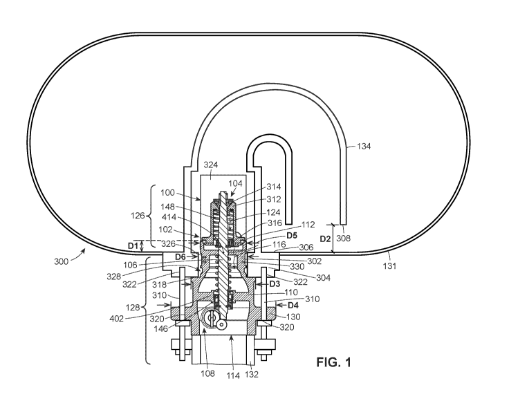
[0027] Fig. 1 illustrates an example internal valve system 300 comprising an
outlet pipe
132, a fluid container 131, and an internal valve 100. The fluid container 131
includes an
opening 302 surrounded by a mounting flange 304, an inner wall 306, and a feed
inlet 308 of
a conduit 134, with the feed inlet 308 being spaced a first distance D1 away
from the inner
wall 306. The internal valve 100, also referred herein as an internal valve
assembly, includes
a poppet valve 102, a bleed valve 104, a valve stem 106, an actuator 108, and
a valve body
110. The valve body 110 includes an inlet 112, an outlet 114, and defines a
main fluid flow
path 116 between the inlet 112 and the outlet 114.
[0028] The valve stem 106 is slidably disposed in the valve body 110. The
poppet valve
102 is arranged to open and close the inlet 112 of the valve body 110 based on
a pressure
6
CA 03055082 2019-08-29
WO 2018/164837 PCT/US2018/018933
and/or a fluid flow rate of a system in which the internal valve 100 is
coupled or installed.
The poppet valve 102 includes a poppet body 312, which is operatively coupled
to the valve
stem 106 by a second spring 146. The poppet body 312 includes a poppet inlet
314 and a
poppet outlet 316. In high pressure environments, it may be necessary to
equalize the
pressure between an upstream fluid source and a downstream fluid source or
fluid container
before the fluid is pumped through the internal valve 100. Such equalization
may be
achieved by the bleed valve 104, which is arranged to open and close the
poppet inlet 314.
The bleed valve 104 includes a bleed valve body 118 having a bleed inlet 120,
a bleed outlet
122, and defining a bleed flow path 124 between the bleed inlet 120 and the
bleed outlet 122.
The valve stem 106 is slidably disposed in the bleed valve body 118 and is
operatively
coupled to both the bleed valve 104 and to the actuator 108.
[0029] An actuator 108 is operatively coupled to the valve stem 106. The
actuator 108 is
operable to shift the valve stem 106 from a first position in which the poppet
valve 102 and
the bleed valve 104 are both closed, to a second position in which the bleed
valve 104 is
open, and a third position in which the bleed valve 104 is closed and the
poppet valve 102 is
open. When the valve stem 106 is in the third position, in response to a
pressure change the
poppet valve 102 is arranged to close and the bleed valve 104 is arranged to
open.
[0030] The internal valve 100 may be installed so that a first or upper
portion 126 of the
valve 100 is arranged to be in fluid communication with a first or upstream
fluid source, e.g.,
the fluid container 131, at which relatively high pressure process fluid may
be introduced.
The upper portion 126 is sized to extend through the opening 302 in the fluid
container 131.
A second or lower portion 128 of the valve 100 is arranged to be in fluid
communication with
a second or downstream fluid source, e.g., the outlet pipe 132, to which the
internal valve 100
provides the process fluid. The valve body 110 includes a flange 130 for
mounting the
internal valve 100 directly to the mounting flange 304 of the fluid container
131 via flange
fasteners 310, and further for mounting the internal valve 100 to the outlet
pipe 132, which
may be provided in a piping system, a storage tank, a bobtail truck system, or
any other
suitable fluid distribution system.
[0031] The first portion 126 of the internal valve 100, which includes the
entire bleed
valve 104, may be immersed in or surrounded by relatively high pressure fluid.
The second
portion 128 may be disposed outside of the fluid container 131 to receive an
outlet pipe 132,
such as a pipe, a hose, or any other suitable conduit, at the outlet 114 of a
valve body 110.
7
CA 03055082 2019-08-29
WO 2018/164837 PCT/US2018/018933
The process fluid may flow from the fluid container 131 via a conduit 134,
such as a hose,
and through the internal valve 100. When the bleed valve 104 is open, the
process fluid may
flow through the bleed flow path 124 and the main flow path 116, through an
outlet 114 of
the valve body 110, and to the outlet pipe 132. When the poppet valve 102 is
open, the
process fluid may flow through the inlet 112, through the main fluid flow path
116, and out
the outlet 114 of the valve body 110.
[0032] The valve body 110 includes a shoulder 318 arranged for sealing
engagement with
the mounting flange 304 of the fluid container 131. The shoulder 318 is
disposed between
the inlet 112 and the flange 130 of the valve body 110. The shoulder 318 is
spaced away
from the inlet 112 and is arranged on the valve body 110 to place the inlet
112 a second
distance D2 away from the inner wall 306 of the fluid container 131 when the
internal valve
100 is connected to the fluid container 131. The second distance between the
inlet 112 and
the inner wall 306 is less than the first distance between the feed inlet 308
of the conduit 134
and the inner wall 306.
[0033] The shoulder 318 has a diameter D3 smaller than a diameter D4 of the
flange 130
of the valve body 110. As a result, the shoulder 318 does not interfere with
the connection
between the flange 130 and the mounting flange 304, and the flange 130 of the
valve body is
arranged to receive a plurality of flange fasteners 310 connectable directly
to the mounting
flange 304 of the fluid container 131. This direct connection may be achieved
a number of
ways. In the arrangement depicted in Fig. 1, the direct connection occurs
because the flange
130 of the valve body includes a plurality of apertures 320 to receive the
plurality of flange
fasteners 310, and the plurality of apertures 320 are arranged for
registration with mounting
apertures 322 in the mounting flange 304 of the fluid container 131. The valve
body 110 is
arranged for connection to the outlet pipe 132 adjacent the outlet 114 of the
valve body 110,
and the outlet pipe 132 is also securable to the valve body 110 via the
plurality of flange
fasteners 310.
[0034] As shown in Fig. 1, a strainer 324 is sized to surround at least a
portion of the
poppet valve 102 and the bleed valve 104. The upper portion 126 of the valve
body 110 has a
diameter D5 and is sized to extend into the opening 302 to surround at least a
portion of the
poppet valve 102 and the bleed valve 104. The diameter D5 of the upper portion
126 of the
valve body is smaller than a diameter D6 of the opening 302 of the fluid
container 131. As a
result, a clearance space is formed between the upper portion 126 of the valve
body 110 and
8
CA 03055082 2019-08-29
WO 2018/164837 PCT/US2018/018933
the opening 302 of the fluid container 131. The upper portion 126 of the valve
body includes
a mounting area 326. The strainer 324 includes an extended portion 328 sized
to be
positioned in the clearance space and arranged for securement to the mounting
area 326 by
fasteners 330.
[0035] Fig. 2 illustrates additional details about the internal valve 100. The
actuator 108
includes a lever 220 coupled to a rotatable cam 222 which rotates the cam 222
about an axis
D to engage the bottom end 140 of the valve stem 106 and shift the valve stem
106 in the
axial direction. While the actuator 108 in the illustrated example includes
the rotatable lever
220 and the cam 222, the internal valve assembly 100 of the present disclosure
is not limited
to the illustrated actuator arrangement. For example, in other embodiments the
actuator 108
may be an automated or manually-operated rotatable or linear drive mechanism
arranged to
shift the valve stem 106 between the first, second, and third positions.
Moreover, another
embodiment of the valve 100 may include an additional operating position in
which the
actuator 108 shifts the valve stem 106 to a position between any two of the
first, second, and
third positions. In one such additional operating position, both the bleed
valve 104 and the
poppet valve 102 may be open.
[0036] As illustrated in Fig. 2, the poppet valve 102 further includes a valve
seat 160 and a
valve disc 168. Similarly, the bleed valve 104 includes a valve seat 208, also
referred to
herein as a bleed seat 208, and a valve disc 204, also referred to herein as a
bleed disc 204. In
the arrangement of Fig. 2, the valve seat 208 and the valve disc 204 of the
bleed valve 104
are disposed above the valve seat 160 and the valve disc 168 of the poppet
valve 102 when
the valve stem 106 is in the first position. In other arrangements, such as
that depicted in Fig.
6A and discussed below, the valve seat 208 and the valve disc 204 of the bleed
valve 104
may be disposed below the valve seat 160 and the valve disc 168 of the poppet
valve 102.
[0037] The function and operation of the internal valve assembly 100 will be
described in
four sequential operating configurations: a closed configuration shown in Fig.
2, a jet bleed
configuration shown in Fig. 3, an open configuration shown in Fig. 4, and a
limited bleed
configuration shown in Fig. 5. The operating configurations of the valve 100
may be selected
by the actuator 108, which is operatively coupled to a bottom end 140 of the
valve stem 106.
The actuator 108 is operable to shift the valve stem 106 between first,
second, and third
positions. The valve stem 106 may be shiftable along a longitudinal axis A of
the internal
valve 100 or along an axis parallel to the longitudinal axis A. When the valve
stem 106 is in
9
CA 03055082 2019-08-29
WO 2018/164837 PCT/US2018/018933
the first position, both the poppet valve 102 and the bleed valve 104 are
closed and the
actuator 108 does not engage with or connect with the bottom end 140 of the
valve stem 106.
A second or closing spring 146 is arranged to bias the internal valve 100 in
the closed
position. Opposite the bottom end 140, a top end 144 of the valve stem 106 is
operatively
coupled to the bleed valve 104, enabling the actuator 108 to control the bleed
valve 104 by
moving the valve stem 106 along the longitudinal axis A. A first or excess
flow spring 148 is
arranged to bias the poppet valve 102 between the open position and the closed
position to
respond to fluid pressure changes. As will be explained in further detail
below, the first
spring 148 is arranged to shift the poppet valve 102 toward the closed
position and is
arranged to open the bleed valve 104 while the valve stem 106 is in the third
position.
[0038] The valve body 110 of the internal valve 100 encloses the second spring
146 and a
portion of the valve stem 106. The second spring 146 may be a closing spring
and is
operatively coupled to the valve stem 106 and is arranged to bias the valve
stem 106 in a
downward direction to close the poppet valve 102 and the bleed valve 104. The
second
spring 146 provides a downward spring force to the valve stem 106, urging the
valve stem
106 to occupy the first position shown in Fig. 2. The second spring 146 is
retained between a
first spring seat 152 and an internal shoulder 156 of the valve body 110.
Further, the valve
body 110 defines a seating surface or valve seat 160 at the inlet 112, which
leads to an orifice
164 connecting the upstream fluid source to the main fluid flow path 116. When
the poppet
valve 102 is in the open position, the main fluid flow path 116 is established
between the inlet
112 and the outlet 114.
[0039] The poppet valve 102 is coupled to the valve body 110 and is operable
to open and
close the inlet 112 of the valve body 110. The poppet valve 102 is also
operatively coupled
to the bleed valve body 118. When the poppet valve 102 shifts between an open
position to
open the inlet 112 and a closed position to close the inlet 112, the bleed
valve body 118
moves toward and away from the inlet 112 of the valve body 110. In other
words, in the
illustrated example of the internal valve 100, the bleed valve body 118 is
inherently part of
the operation of the poppet valve 102. In the illustrated example, the bleed
valve body 118 is
depicted as a disc-type valve assembly that includes or carries a valve disc
168 of the poppet
valve 102 that engages the valve seat 160 to restrict the flow of fluid
through the valve body
110. The poppet valve 102 is shiftable between an open position in Fig. 4
where the valve
disc 168 and the bleed valve body 118 are spaced away from the valve seat 160,
and a closed
CA 03055082 2019-08-29
WO 2018/164837 PCT/US2018/018933
position in Figs. 2, 3, and 5 where the valve disc 168 is seated against the
valve seat 160. A
disc retainer 172 couples the disc 168 to a disc holder portion 176 of the
bleed valve body
118 by one or more fasteners 180.
[0040] The bleed valve 104 is coupled to the valve stem 106, and includes the
bleed valve
body 118 having a bore 184 that houses the first spring 148. The first spring
148 may be an
excess flow spring and is arranged to bias the bleed valve body 118 toward the
seating
surface 160 to restrict the fluid flow through the orifice 164 when the flow
rate through the
valve 100 exceeds a specified or predetermined flow rate, e.g., an excess flow
limit or rate of
the valve 100. The first spring 148 includes a bottom end 190 and a top end
192, and is
retained between a second spring seat 194 and a retaining shoulder 196, which
is defined by
the bore 184 and a cylindrical portion 198. The top end 192 of the first
spring 148 bears
against the retaining shoulder 196 and the bottom end 190 of the first spring
148 bears against
the second spring seat 194. The second spring seat 194 is operatively coupled
to the valve
stem 106 such that the second spring seat 194 moves with the valve stem 106 as
the stem 106
shifts in the axial direction along the longitudinal axis A. The spring seat
194 defines at least
a portion of a flow aperture 210 disposed in the bleed flow path, which
permits fluid
communication between the bleed inlet 120 and the bleed outlet 122. A bleed
port 200 may
be integrally formed with the bleed valve body 118, and in particular, may be
defined as the
opening formed by the cylindrical portion 198 of the bleed valve body 118. The
bleed port
200 is disposed within the bleed flow path 124 and fluidly connects the bleed
inlet 120 and
the bore 184, and the bore 184 fluidly connects the bleed inlet 120 and the
bleed outlet 122.
A bleed disc 204 is shiftable between an open bleed position, shown in Figs. 2
and 4, where
the bleed disc 204 is spaced away from a bleed seat 208 and the bleed port
200, and a closed
bleed position, shown in Figs. 1 and 3, where the bleed disc 204 is seated
against the bleed
seat 208, sealing the bleed port 200 from the upstream fluid source. Taken
together, the
poppet valve 102 and the bleed valve 104 form the internal valve 100.
[0041] Turning now specifically to Fig. 2, the internal valve 100 is in the
first or closed
operating configuration. In the closed configuration, the poppet valve 102 is
in the closed
position and the bleed valve 104 is in the closed bleed position such that the
outlet 114 is
sealed off from the upstream fluid source. The valve disc 168 carried by the
bleed valve
body 118 is biased toward the closed position by the first spring 148 and/or
by the pressure of
the upstream fluid source at the inlet 112. The bleed disc 204 of the bleed
valve 104 is biased
11
CA 03055082 2019-08-29
WO 2018/164837 PCT/US2018/018933
toward the closed bleed position by the second spring 146 via the valve stem
106. When both
the poppet valve 102 and the bleed valve 104 are closed, the valve disc 168
engages the valve
seat 160 to prevent the flow of fluid through the orifice 164, and the bleed
disc 204 engages
the bleed seat 208 to prevent the flow of fluid through the bleed port 200.
[0042] In Fig. 2, the operating lever 220 of the actuator 108 is in a first
position whereby
the rotatable cam 222 does not engage the bottom end 140 of the valve stem
106. When,
however, the actuator 108 is operated to shift the valve stem 106 in the axial
direction along
the longitudinal axis A from the position shown in Fig. 2 to the position
shown in Fig. 3, the
lever 220 is moved to a second position, which causes the cam 222 to rotate
about the axis D
until the cam 222 engages the bottom end 140 of the valve stem 106. In this
example, the
second position of the lever 220 corresponds to a midpoint of its travel path
positioned 35
degrees relative to the first position. Movement of the valve stem 106 to the
position shown
in Fig. 3 compresses the second spring 146 between the first spring seat 152
and the valve
body 110, causing the bleed disc 204 to move away from the bleed seat 208,
thereby moving
the internal valve 100 from the closed operating configuration to the jet
bleed configuration.
[0043] In the jet bleed configuration of Fig. 3, the valve stem 106 is in the
second position
and the poppet valve 102 remains closed, but bleed valve 104 is in the open
position, thereby
permitting fluid from the upstream fluid source to enter the bleed inlet 120
and equalize the
pressure differential across the valve 100. A portion of the valve stem 106
that is disposed in
the bleed port 200 includes a reduced diameter or a recessed portion 224 to
permit fluid flow
between the cylindrical portion 198 of the bleed valve body 118 and the valve
stem 106. In
the jet bleed configuration, the recessed portion 224 forms a gap G1 between
the valve stem
106 and the bleed port 200. So configured, the bleed valve 104 may allow for
greater fluid
flow through the bleed port 200 to the bleed flow path 124, which may result
in quicker
pressure equalization across the valve 100. The flow aperture 210 formed in
the second
spring seat 194 fluidly connects the bleed flow path 124 to the inlet 112 of
the poppet valve
102, permitting fluid to continuously flow through the valve 100 until the
upstream pressure
and downstream pressure are nearly equal. The poppet valve 102 remains in the
closed
position until a pressure of the upstream fluid source is less than the spring
force of the first
spring 148, causing the first spring 148 to expand and push the bleed valve
body 118 upward
in the axial direction toward the open position. The gap G1 provided by the
placement of the
recessed portion 224 of the stem 106 relative to the bleed port 200 together
with the flow
12
CA 03055082 2019-08-29
WO 2018/164837 PCT/US2018/018933
aperture 210 of the second spring seat 194 may expedite equalization of the
internal valve
100.
[0044] The second spring 146 and the first spring 148 are compressed while
fluid flows
from the upstream fluid source through the bleed valve 104 and into the inlet
112 of the
poppet valve 102. The first spring seat 152 is operatively coupled to the
valve stem 106 such
that the first spring seat 152 applies a reactive force against the second
spring 146 when the
valve stem 106 shifts upward, causing the second spring 146 to compress
against the internal
shoulder 156 of the valve body 110. The second spring seat 194 is operatively
coupled to the
valve stem 106 via a ring 230, e.g., a clip, and moves further into the bore
184 of the bleed
valve 104 as the valve stem 106 shifts upward in the axial direction. The
first spring 148
compresses between the retaining shoulder 196 of the bleed valve body 118 and
the second
spring seat 194. Depicted in Fig. 3, the force exerted by the first spring 148
onto the
retaining shoulder 196 and spring seat 194 is not yet sufficient to overcome
the force of
pressure of the upstream fluid source on the poppet valve 102, and therefore
the poppet valve
102 remains in the closed position. In another example, the second spring seat
194 may be
coupled to the valve stem 106 by pin extending through the valve stem 106 or
by a notch or a
groove formed in the surface of the valve stem 106.
[0045] When the actuator 108 is operated to shift the valve stem 106 in the
axial direction
from the second position (Fig. 3) to a third position (Fig. 4), the lever 220
is moved to a third
position by completing its travel path, thereby further rotating the cam 222
about the axis D
and driving the valve stem 106 further upward. Movement of the valve stem 106
to the
position shown in Fig. 4 further compresses the second spring 146 and the
second spring 148,
which forces the poppet valve 102 to open as the pressure of the upstream
fluid source
approximately equals the pressure of the downstream fluid source, thereby
moving the
internal valve 100 from the jet bleed configuration to the open operating
configuration.
[0046] Fig. 4 illustrates the internal valve 100 in the open operating
configuration, where
the poppet valve 102 is in the open position, permitting fluid to flow from
the upstream
pressure source into the inlet 112 of the valve 100, into the orifice 164,
through the main flow
path 116, and out of the valve 100 via the outlet 114. The bleed seat 208 of
the bleed valve
body 110 meets the bleed disc 204 when the first spring 148 expands in the
axial direction
and shifts the bleed valve body 118 upward and away from the inlet 112. In
response to the
13
CA 03055082 2019-08-29
WO 2018/164837 PCT/US2018/018933
pressure differential across the valve 100, the expansion of the first spring
148 causes the
second spring seat 194 to slide downward within to the bore 184.
[0047] When, however, the upstream pressure overcomes the spring force of the
second
spring 148, the poppet valve 102 is moved back to the closed position.
Alternatively, the
flow rate through the valve 100 may exceed a specific or predetermined flow
rate, causing the
bleed valve body 118 to move toward the valve seat 160 to close the poppet
valve 102. In
any event, the closing of the poppet valve 102 moves the valve 100 from the
open operating
configuration illustrated in Fig. 4 to the limited bleed configuration
illustrated in Fig. 5. In
the limited bleed configuration, the bleed valve 104 is in the open bleed
position. The
recessed portion 224 of the valve stem 106 is thus placed above the bleed port
200. In this
position, the recessed portion 224 is not disposed in the bleed port 200
sufficiently to form
gap Gl, and instead a gap G2 is defined between the valve stem 106 and the
valve port 200.
Gap G2 is smaller than gap G1 formed by the recessed portion 224 of the valve
stem 106 and
the valve port 200 in the jet bleed configuration. The formation of gap G2
permits a limited
amount of fluid to bleed through the bleed port 200 relative to the amount of
fluid that is
permitted to bleed through the bleed port 200 in the jet bleed configuration.
[0048] According to the teachings of the present disclosure, the bleed valve
104 and the
poppet valve 102 provide an excess flow functionality that maintains system
safety and
permits the bleed valve 104 and the poppet valve 102 to open and close, as
illustrated in Figs.
2-5. The excess flow function protects the system by automatically restricting
fluid flow into
the inlet 112 when a flow rate becomes too high within the valve 100. In
particular, the
poppet valve 102 operates based on a pressure differential between the inlet
pressure and the
outlet pressure, and the first spring 148 has an excess flow spring rate that
causes the bleed
valve body 118 and the valve disc 168 to move toward the seating surface 160
when the flow
rate through the valve 100 exceeds a specific or predetermined flow rate. When
the inlet
pressure is substantially greater than the outlet pressure, the bleed valve
body 118 carrying
the valve disc 168 remains biased toward the seating surface 160 in the closed
configuration
depicted in Fig. 2. The bleed valve 104 is arranged to equalize or balance the
pressure
between the inlet 112 and outlet 114, and the bleed valve 104 may place the
valve 100 in the
jet bleed configuration shown in Fig. 4 to allow a certain amount of fluid to
bleed into the
internal valve 100. When the inlet pressure is approximately equal to the
outlet pressure, the
first spring 148 opens the poppet valve 102 to allow fluid to flow through the
internal valve
14
CA 03055082 2019-08-29
WO 2018/164837 PCT/US2018/018933
100 as shown in Fig. 4. Once the poppet valve 102 opens, a fluid flow greater
than the spring
rate of the first spring 148 may force the poppet valve 102 to close against
the first spring 148
shown in Fig. 5. In the limited bleed configuration, the bleed valve 104 is
opened to permit a
smaller amount of fluid to bleed into valve 100.
[0049] Turning to Fig. 6A, an alternate arrangement of an internal valve 100
of the present
disclosure is illustrated. In this arrangement, the valve stem 106 includes a
first piece 340
and a second piece 342. The poppet body 102 is operatively coupled to the
first piece 340 of
the valve stem 106, and the bleed valve 104 is operatively coupled to the
second piece 342 of
the valve stem 106. In this arrangement, the first or excess flow spring 148
is disposed above
the valve seat 208 of the bleed valve 104. Further, the valve seat 208 and the
valve disc 204'
of the bleed valve 104 are disposed below the valve seat 160 and valve disc
168 of the poppet
valve 102. A strainer 324 surrounds at least a portion of the poppet valve 102
and the bleed
valve 104. An extended portion 328 of the strainer 324 is arranged for
securement to a
mounting area 326 of the valve body 110 by fasteners 330. The fasteners may be
screws,
nails, or any other fastener common in the art. Fig. 6B provides a view of the
strainer 324 on
its own, showing the extended portion 328 and the fasteners 330.
[0050] Fig. 7 illustrates an alternate arrangement of an internal valve 100 of
the present
disclosure in which the first spring 148 is an excess flow spring, and
includes a first portion
344 bearing against a first portion of the valve stem 106 via spring seat 194.
The first portion
of the valve stem 106 against which the first portion 344 of the first spring
148 bears via
spring seat 194 is obscured in Fig. 7, but those of skill in the art will
readily understand that
spring seat 194 causes the first portion 344 to bear against a first portion
of the valve stem
106 in a conventional or any suitable manner. The first spring 140 also
includes a second
portion 346 bearing against the poppet body 312. The internal valve includes a
second or
closing spring 146 disposed within the valve body 110. The second spring 146
is coupled to
the valve stem 106 and is arranged to bias the valve stem 106 toward the first
position. At
least a portion of the first spring 140 is nested inside the second spring
146.
[0051] Fig. 8 illustrates an alternate arrangement of an internal valve 100 in
which the
shoulder 318 of the body is an upper surface of the flange 130 of the valve
body 110.