Note: Descriptions are shown in the official language in which they were submitted.
CA 03055479 2019-09-05
WO 2018/162876 PCT/GB2018/050433
1
INTERNAL COMBUSTION ENGINE
FIELD OF THE INVENTION
[0001] The present invention relates to an internal combustion engine, and a
method
of assembling an internal combustion engine.
BACKGROUND OF THE INVENTION
[0002] Most internal combustion engines comprises a piston head moveable
within a
cylinder coupled to a crankshaft by a con-rod. In some alternative internal
combustion engines, such as described in WO 2015/107330, a piston head is
coupled
to a track having a cam surface, the piston head being provided with one or
more cam
followers which run along the track to control movement of the piston head.
The
present invention relates to improvements in such an alternative internal
combustion
engine.
SUMMARY OF THE INVENTION
[0003] A first aspect of the invention provides an internal combustion engine
comprising a casing and a piston arrangement including a piston coupled to a
track;
wherein the track is coupled to a shaft and has an inner cam surface and an
outer cam
surface, and the piston is coupled to the track by followers which run on the
respective
inner and outer cam surfaces of the track to control motion of the piston;
wherein a
sliding element is connected to the piston, the sliding element extending
below the
piston head and comprising a profiled slider surface which engages a
corresponding
profile in the casing, and the followers are mounted on the sliding element.
[0004] As the track rotates relative to the casing, the piston head moves in
reciprocating motion according to the path of the inner and outer cam
surfaces. The
invention is advantageous in that the corresponding profiles of the slider and
casing
can constrain motion of the sliding element with respect to the casing in both
directions orthogonal to the direction of motion of the reciprocating piston.
[0005] A second aspect of the invention provides an internal combustion engine
comprising a piston arrangement including a piston coupled to a track; wherein
the
track is coupled to a shaft and has a cam surface, and the piston has a
follower which
CA 03055479 2019-09-05
WO 2018/162876 PCT/GB2018/050433
2
runs on the cam surface of the track to control motion of the piston; the
engine further
comprising a casing, wherein the casing comprises at least two plates having a
cutout
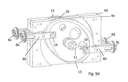
for receiving the track and a bore for receiving the shaft, and at least two
end plates
coupled transverse to the plates; wherein at least one cylinder bore is formed
in the
end plates, and the piston is arranged to move in reciprocating motion in the
cylinder
bore.
[0006] A third aspect of the invention provides a method of assembling an
internal
combustion engine comprising a casing and a piston arrangement including a
piston
coupled to a track; wherein the track is coupled to a shaft and has an inner
cam surface
and an outer cam surface, and the piston is coupled to the track by followers
which
run on the respective inner and outer cam surfaces of the track to control
motion of the
piston; wherein a sliding element is connected to the piston, the sliding
element
extending below the piston head and comprising a profiled slider surface which
engages a corresponding profile in the casing, and the followers are mounted
on the
sliding element; wherein the casing comprises at least two plates having a
cutout for
receiving the track and a bore for receiving the shaft, and at least two end
plates,
wherein at least one cylinder bore is formed in the end plates, and the piston
is
arranged to move in reciprocating motion in the cylinder bore; the method
including
the steps of: a) coupling the piston arrangement to the shaft by coupling the
track to
the shaft and coupling the piston to the track; b) bringing the at least two
plates
together on either side of the track; and c) bringing the end plates together
so as to be
transverse to the plates; and d) coupling the end plates to the plates.
[0007] By assembling the plates on either side of the track, the engine can be
constructed easily and engine capacity can be scaled up or down by increasing
or
decreasing the number of tracks, pistons and used plates. The plates may be
substantially identical and/or mirror images of one another. The architecture
of the
engine is therefore highly scalable with few components. The end plates
contain the
cylinder bore(s) and advantageously allow cooling passages to circulate where
desired. The end plates may also provide a fixing for the cylinder head. The
end plates
may vary in size and configuration according to the engine capacity and number
of
pistons etc.
CA 03055479 2019-09-05
WO 2018/162876 PCT/GB2018/050433
3
[0008] The sliding element may be rigidly attached to the piston by one or
more
fasteners or alternatively may be integrally formed with the piston.
[0009] The sliding element may be arranged to have a running clearance with
the
track.
[0010] The followers may comprise one or more plain bearings or roller
bearings.
[0011] The sliding element may comprise two limbs each extending below the
piston
so as to straddle the track. The profiled slider surface may be provided on
each limb,
with each profiled slider surface engaging a respective profile in the casing.
[0012] The followers may be arranged such that at least one follower which
runs on
the outer cam surface of the track is located between the two limbs of the
sliding
element.
[0013] The followers may be arranged such that each of the two limbs of the
sliding
element has at least one follower which runs on the inner cam surface of the
track.
[0014] The engine may further comprise a pair of timing wheels coupled to the
shaft
one on either side of the track, each timing wheel having an inner cam surface
substantially matching the inner cam surface of the track, and wherein each
limb of
the sliding element has at least one follower which runs on the inner cam
surface of
the respective timing wheels.
[0015] The profiled slider surface may be arranged to be lubricated such that
the
profiled slider surface contacts the casing profile via a layer of lubricant.
[0016] The profiled slider surface may comprise an oil pick-up aperture
adapted to
receive oil from an elongate slot in the casing profile. The elongate slot
preferably
does not extend up to an end of the casing profile furthest from the piston.
This may
help contain the oil.
[0017] The inner and outer cam surfaces of the track may be arranged to be
lubricated
such that the followers contact the cam surfaces via a layer of lubricant.
CA 03055479 2019-09-05
WO 2018/162876 PCT/GB2018/050433
4
[0018] The followers may each include a roller mounted on plane bearing shaft
fixed
to the sliding element. The plane bearing shaft may include an oil-pick up
aperture
adapted to receive oil from the sliding element.
[0019] The track may be a radial track with the inner and outer cam surfaces
arranged
as inner radial and outer radial surfaces with respect to an axis of rotation
of the track.
[0020] The engine may further comprise a plurality of the piston arrangements
comprising a plurality of the pistons coupled to one or more of the tracks.
For
example, two pistons may be coupled to one of the tracks, the pistons being
coupled to
substantially opposite sides of the track. Multiple tracks may be arranged
along the
axial shaft direction. Two such tracks may be arranged 180 degrees out of
phase with
one another on the shaft for balancing the engine.
[0021] Each track may be accompanied by a pair of timing wheels. The pair of
timing
wheels may be arranged one on each side of the track. Each timing wheel may
comprise a cam surface. The cam surface of the timing wheel may correspond
with
the path of one of the inner or outer cam surfaces of the respective track.
[0022] The casing may comprise at least two plates having a cutout for
receiving the
track and a bore for receiving the shaft, and at least two end plates coupled
transverse
to the plates. At least one cylinder bore may be formed in the end plates, and
the
piston may be arranged to move in reciprocating motion in the cylinder bore.
[0023] One plate may be provided between each track and timing wheel along the
shaft axial direction. A side plate may be attached to an outer side of the
plate(s) in the
shaft axial direction. The plates of the casing may be attached together by a
plurality
of fasteners. The end plates may assist in retaining the plates together.
BRIEF DESCRIPTION OF THE DRAWINGS
[0024] Embodiments of the invention will now be described with reference to
the
accompanying drawings, in which:
[0025] Figure 1 shows an engine:
[0026] Figure 2 shows the engine with various components omitted;
CA 03055479 2019-09-05
WO 2018/162876 PCT/GB2018/050433
[0027] Figures 3a and 3b show side and perspective views the power transfer
mechanism for one of the pistons in the engine with certain components
omitted;
[0028] Figure 4a and 4b show perspective and front views of the piston and
sliding
element having followers;
[0029] Figure 5 shows the piston and sliding element with the followers
omitted;
[0030] Figure 6 shows the piston and sliding element with the follower
mountings
attached;
[0031] Figure 7a to 7e show side, top, other side, end and perspective views
of the fin
plate of the engine;
[0032] Figure 8 and 8b show perspective and side views of the power transfer
mechanism having two tracks and two pistons per track;
[0033] Figures 9a to 9h show the engine at various stages during assembly; and
[0034] Figure 10 shows an adjuster between the plates of the engine casing.
DETAILED DESCRIPTION OF EMBODIMENT(S)
[0035] Figure 1 shows an internal combustion engine 1 comprising a block
assembly
2, two head assemblies 3a, 3b and an exhaust system (omitted). The head
assemblies
3a, 3b and exhaust system will not be discussed in detail here. The block
assembly 2
comprises a plurality of casing members, or plates, including side plates 4a,
4b, fin
plates 4c, 4d, 4e, 4f, end plates 5a, 5b, top cover 6a and bottom cover 6b.
[0036] Figure 2 shows the engine 1 with the head assemblies 3a, 3b, top and
bottom
covers 6a, 6b and end plate 5b removed so that further parts of the engine are
visible.
The end plate 5b has two bores, each bore receiving a respective cylinder
liner 7a, 7b,
each cylinder liner receiving a respective piston 8a, 8b, the heads of which
are visible
in Figure 2. Likewise, although not shown in Figure 2, the end plate 5a has
two bores
for two further cylinder liners of respective pistons. The engine 1 has a
total of four
pistons coupled in an opposed relationship to two tracks 9a, 9b, the tops of
which are
visible in Figure 2. The engine 1 therefore includes four piston assemblies
and the
structure and functioning of the first piston assembly will be described in
detail,
CA 03055479 2019-09-05
WO 2018/162876 PCT/GB2018/050433
6
although it will be appreciated that the second, third and fourth piston
assemblies are
structurally and functionally similar to the first piston assembly.
[0037] The first piston assembly is shown in Figures 3a and 3b. The first
piston
assembly 10a comprises a piston 80 with a piston head 8a movable within the
cylinder
liner 7a (visible in Figure 2). The piston head 8a is coupled to an output
shaft 11
having an axis of rotation 11 a and an output flange 12 via a track 13. The
track 13 is
mounted on and rotationally fixed with respect to the output shaft 11 via a
spline
connection (not visible). The track 13 rotates with the output shaft 11 about
the axis of
rotation 11 a relative to the piston head 8a and the cylinder sleeve 7a.
[0038] Each track 13 has a radially outer cam surface 14 extending around its
circumference. The track 13 also has a radially inner cam surface 15 located
on an
underside of an overhanging portion, the inner cam surface 15 facing away from
the
outer cam surface 14, i.e. in the opposite direction. A planar edge surface 16
extends
between the outer and inner cam surfaces of the track 13.
[0039] The piston 80 includes the piston head 8a and a stabilising sliding
element 17
connected to and extending below the piston head. The sliding element 17 and
piston
head 8a are integrally formed in the illustrated embodiment, but alternatively
the
sliding element 17 may be formed as a separate part from the piston head 8a
and
connected by fasteners, e.g. bolts. The piston 80 further includes followers
mounted
on the sliding element 17 which run on the respective inner and outer cam
surfaces of
the track to control motion of the piston. In the illustrated embodiment, the
followers
comprise a single outer cylindrical roller 18 and four inner cylindrical
rollers 19, each
rotatably mounted to the piston 80.
[0040] The outer cylindrical roller 18 has a cylindrical outer radial surface
which runs
on the outer cam surface 14 of the track 13 and transmits load between the
piston 80
and the track 13. The inner cylindrical rollers 19 comprise two pairs of
cylindrical
rollers. In each pair of rollers, there is a track follower which runs on the
inner cam
surface 15 of the track 13, and a timing wheel follower which runs on an inner
cam
surface of a timing wheel which will be described later. The stabilising
sliding
element 17 has a bifurcated construction forming a left limb, or arm, 20 and a
right
CA 03055479 2019-09-05
WO 2018/162876 PCT/GB2018/050433
7
limb, or arm, 21. The arms 20, 21 depend downwardly away from the piston head
8a
so as to straddle either side of the track 13. The outer cylindrical roller 18
is rotatably
mounted on a journal 22 extending between the left arm 20 and the right arm 21
such
that the roller 18 is captive between the arms 20, 21.
[0041] The inner cylindrical rollers 19 are arranged in pairs, one pair on
each
respective arm 20, 21. The track following roller of the pair of inner rollers
19 is held
captive between the arm 20 and the track wheel centre 23. The timing wheel
follower
of the pair of inner followers 19 is held captive between the arm 20 and the
timing
wheel. The inner cylindrical rollers 19 are mounted on a journal 24 fixed to
the left
arm 20 of the stabilising sliding element 17. A similar pair of rollers 19 on
a journal
24 is mounted at the lower end of the right arm 21 of the bifurcated
stabilising sliding
element 17. The profile of the inner and outer cam surfaces 14, 15 of the
track 13 are
profiled such that as the track 13 rotates about shaft axis 1 la the outer
cylindrical
roller 18 and the inner cylindrical rollers (track followers) 19 maintain
continuous
rolling contact with the outer and inner cam surfaces 14, 15 of the track.
Since the
outer and inner cam surfaces 14, 15 of the track 13 are non-circular about the
rotation
axis 11 a, the piston head 8a is caused to move in reciprocating linear motion
within
the cylindrical inner surface of the piston liner 7a, the piston moving in
reciprocating
linear motion in accordance with the profile of the track.
[0042] The piston 80 is shown in greater detail in Figures 4a and 4b. The arms
20, 21
of the bifurcated stabilising sliding element 17 are substantially planar and
parallel
and are dimensioned so as to provide a clearance fit with the planar side
surfaces 16 of
the track 13. The piston 80 includes several weight-saving cut-outs 25 beneath
the
piston head 8a. The stabilising element 17 includes oil pick-ups 26 which are
arranged
to receive oil under pressure and to distribute this around the piston 80 via
internal oil
passages to locations requiring lubrication, for example the interface between
the
outer cylindrical roller 18 and the journal 22 and the interfaces between the
inner
cylindrical rollers 19 and the journals 24.
[0043] Figure 5 shows the piston 80 with the followers and their respective
journals
removed, and Figure 6 shows the piston 80 with only the journals for the
followers in
CA 03055479 2019-09-05
WO 2018/162876 PCT/GB2018/050433
8
situ. As can be seen from Figure 5, the circular apertures 27 for receiving
the journals
24 each have an oil delivery aperture in fluid communication with the oil pick-
ups 26.
The journal 22 for the outer cylindrical roller 18 is generally cylindrical
with one end
cut back to form a generally square profile to prevent rotation of the journal
22. The
ends of journal 22 are located respectively in substantially square and
substantially
circular apertures in the arms 20, 21 of the piston 80.
[0044] The arms 20, 21 of the bifurcated stabilising element 17 each comprise
a
profiled slider surface 20a, 21a. The profiled slider surfaces 20a, 21a engage
a
corresponding profile in the block assembly 2. As can be seen from Figures 5
and 6 in
particular, the profiled slider surface 20a and the profiled slider surface
21a each have
a generally U-shaped profile. The profile of the slider surface 20a is
substantially a
mirror image of the profile of the slider surface 21a. The profiled slider
surfaces 20a,
21a constrain the motion of the piston 80 for movement only along the
longitudinal
axis of the cylindrical cylinder liner 7a. This constraint ensures that the
facing surfaces
of the arms 20, 21 of the bifurcated stabilising sliding element 17 do not
contact the
side surfaces 16 of the track 13.
[0045] Figure 7a to 7e illustrate one of the fin plates 4c that make up the
block
assembly 2 as shown in Figure 2. The fin plates 4c and 4e are identical and
the fin
plates 4d and 4f are mirror images of the fin plates 4c. The fin plate 4c is,
in the
illustrated embodiment, a machined metallic plate having fixing holes for
securing to
neighbouring plates 4a, 4d, 6a, 6b, 5a and 5b of the block assembly 2. The
plate 4c has
a through-bore 31 which receives the rotatable shaft 11. The plate 4c is
arranged to
receive a track wheel 13 on one side of the bore 31 and to receive a timing
wheel 30
on the other side of the bore 31. As illustrated, the track wheel 13 is
arranged to sit
within recess 32 on the first side of the fin plate shown in Figure 7a, and
the timing
wheel 30 is arranged to sit within recess 33 on the opposite side of the fin
plate shown
in Figure 7c.
[0046] The fin plate 4c has a pair of cut-outs forming a generally U-shaped
profile
extending from opposing end faces 34, 35 of the plate 4c. These cut-outs are
the
casing profiles 38a, 38c which are shaped to correspond with the generally U-
shaped
CA 03055479 2019-09-05
WO 2018/162876 PCT/GB2018/050433
9
profiles 20a, 21a of the bifurcated stabilising sliding element 17 of the
pistons 80. On
each side of the generally U-shaped profiles 38a, 38c is an oil delivery slot
39 which
each cooperate with one of the oil pick-ups 26 of the piston 80. As the
sliding element
17 of the piston 80 slides within the respective profiles 38a, 38c of the fin
plate 4c of
the block assembly 2, the oil pick-up 26 moves over the elongated slot 39 to
maintain
continuous oil delivery from the block assembly 2 to the parts of the piston
80 which
require lubrication. Oil is delivered to the elongated slots 39 through oil
delivery
conduits formed in the fin plate 4c. The length of the cut-outs in the fin
plate 4c which
form the casing profiles 38a, 38c are longer than the intended path of
reciprocating
linear motion of the piston 80 such that any build up in the engine does not
impede
motion of the piston 80. By arranging the fin plate 4c and its mirror
counterpart 4d
back-to-back on either side of the piston 80, and by matching the profile of
the slider
surfaces 20a and 21a to the casing profiles, the motion of the piston 80 is
constrained
by its stabilising sliding element 17 for motion only along the longitudinal
axis of the
cylinder liner 7a.
[0047] Although in Figure 3a only a single piston 80 mounted on a single track
13 is
shown, the engine 1 illustrated has two tracks 13 and four pistons 80 as
mentioned
above. Figures 8a and 8b illustrate perspective and top plan views of the
piston
arrangement in the engine 1 so as to show all four piston heads 8a, 8b, 8c,
and 8d
arranged on two identically profiled tracks 13 arranged 180 degrees out of
phase with
one another on the shaft 11. Each track 13 has a pair of pistons 8a, 8c and
8b, 8d. The
pistons 8a, 8c are arranged in an opposed relationship on the track 13 so as
to move
along parallel but offset paths of linear reciprocating motion. The pistons
8b, 8d are
similarly arranged. By providing the piston arrangement having the tracks 13
180
degrees out of phase with one another and by having two pistons per track in
an
opposed relationship on offset parallel axes, perfect weight balancing of the
engine 1
is achievable without any additional counterweights.
[0048] As best shown in Figure 8b, each track 13 is accompanied by a pair of
timing
wheels 30 arranged on opposite sides of the track 13. Each timing wheel 30 has
an
inner cam profile identical to that of its accompanying track 13. The timing
wheels 30
are fixed to rotate with the shaft 11 such that the angular position of the
track 13 and
CA 03055479 2019-09-05
WO 2018/162876 PCT/GB2018/050433
its accompanying two timing wheels is always synchronised. Since one track 13
is 180
degrees out of phase with the other track 13, the two pairs of timing wheels
30 are
similarly arranged 180 degrees out of phase with the other pair of timing
wheels 30
about the shaft axis of rotation 11 a.
[0049] In operation of the engine, the outer cylindrical rollers 18 of each of
the four
pistons bear against and roll along the outer cam surfaces 14 of the tracks
13, and the
inner cylindrical rollers 19 of each of the four pistons bear against and roll
along the
inner cam surfaces 15 of the tracks 13 and of the timing wheels 30. As the
tracks 13
and timing wheels 30 rotate with the engine 1, the piston heads 8a to 8d move
within
their respective cylinder sleeves 7a to 7d in accordance with the path shape
of the
tracks 13 and timing wheels 30.
[0050] During some portions of the operating cycle the pistons are driven by
the track,
for example during intake, compression and exhaust strokes. During some
portions of
the operating cycle the track is driven by the piston such that work can be
extracted
from the output shaft 11, for example during power strokes. Since the path
shape of
the tracks 13 and their accompanying timing wheels 30 may be given any desired
shape the piston is not constrained to follow simple harmonic motion as in
most
conventional internal combustion engines but can instead have any desired
displacement profile. The displacement profile may, for example, include
multiple
different local top dead centre positions at different heights and/or multiple
different
bottom dead centre positions at different heights. As can be seen from Figure
3a, the
track 13 is shaped such that the piston completes 4 strokes for every output
shaft
revolution and experiences top dead centre positions and different bottom dead
centre
positions at different heights.
[0051] Although in the illustrated embodiment the engine comprises two tracks
and
four pistons, in alternative embodiments an engine may comprise any number of
tracks (for example 1, 2, 3 or more) and may have any number of piston
arrangements
(for example 1, 2, 3 or more) operated by each track. Depending on the number
of
tracks and pistons some weight-balancing of the engine may be required to
cancel
engine vibration.
CA 03055479 2019-09-05
WO 2018/162876 PCT/GB2018/050433
11
[0052] The engine is assembled by the following steps, with reference to
Figures 9a to
9h. The method recited below does not include all steps required to assemble
all of the
components forming part of the engine 1 but has instead been reduced to the
major
steps for assembling the power transfer mechanism and casing for clarity:
[0053] Arrange track 13 and timing wheel 30 on opposite sides of fin plate 4e
and
couple to shaft 11, then insert pistons 8b and 8c without follower 19 until
followers
18 contact the outer cam surface of track 13 (Figure 9a).
[0054] Feed the second timing wheel 30 over the far end of shaft 11 so as to
be 180
degrees out of phase with the first timing wheel 30 (Figure 9b).
[0055] Feed fin plate 4a over the far end of shaft 11 and bring into contact
with fin
plate 4e, then feed the second track 13 over the far end of shaft 11 and
insert pistons
8a and 8d with the followers 19 removed (Figure 9c).
[0056] Attach all four pairs of inner cylindrical rollers (followers) 19 to
the four
pistons 80 so as to couple all four pistons to the two tracks 13 (Figure 9d).
[0057] Attach fin plate 4f and fin plate 4c to opposite sides of the two
tracks 13
(Figure 9e).
[0058] Attach the two further timing wheels 30 (again 180 degrees out of phase
with
one another) to the open sides of the block assembly (Figure 9g).
[0059] Attach end plates 4a and 4b to complete the main section of the block
assembly and install cylinder liners and end plates 5a, 5b (Figure 9h).
[0060] Once the plates of the engine block are all assembled, the plates are
fixed
together, e.g. by bolting, before the addition of the two head assemblies 3a,
3b and the
top and bottom covers 6a, 6b so as to complete the engine as shown in Figure
1.
[0061] The tracks 13, timing wheels 30 and spacers mounted along the shaft 11
may
be all bolted together through hubs of the tracks, timing wheels and spacers.
Needle
rollers may be provided around each of the tracks and timing wheels, the
needle
rollers mounted spaced from the plates.
CA 03055479 2019-09-05
WO 2018/162876 PCT/GB2018/050433
12
[0062] Although in the illustrated embodiment the profiled slider surface and
corresponding casing profile are substantially U-shaped, these profiled
surfaces may
take different shapes. The cut out forming the casing profile may in
alternative
embodiments be enlarged to receive a separate insert having inner an profile
that
contacts the profiled slider surface.
[0063] Figure 10 shows an optional adjuster mechanism between the casing fin
plates
4e and 4f. A similar adjuster mechanism may be provided between the fin plates
4c
and 4d. The adjuster mechanism in the illustrated example includes four
adjuster bolts
90, although a different number of bolts or other adjustment means may be
used. The
adjuster bolt heads are accessed through a clearance hole (not shown) in the
casing
side plate 4b from outside the engine, and similarly the adjuster bolt heads
for the
adjuster mechanism for the fin plates 4c and 4d are accessed through apertures
in the
casing side plate 4a. The adjuster mechanism acts to push the plate 4f away
from plate
4e in the direction of arrows C-C, which in the illustrated example is by
rotating the
threaded bolts 90 in respective threaded holes in plate 4f, which causes the
shank ends
of the bolts to bear against plate 4e. This adjustment can be used to set the
clearance
between the outer side surfaces of the stabilising eliding element 17 of the
piston 80
and the U-shaped profiles 38e, 38f of the casing.
[0064] The threaded holes of the adjuster bolts 90, as well as the holes for
the bolts
holding the plates 4a-4f of the casing together, may have o-rings. Further
optionally,
the plates may have a groove 92 for receiving a seal or sealant material for
sealing
between adjacent plates.
[0065] Although the invention has been described above with reference to one
or
more preferred embodiments, it will be appreciated that various changes or
modifications may be made without departing from the scope of the invention as
defined in the appended claims.