Note: Descriptions are shown in the official language in which they were submitted.
. CA 03055588 2019-09-06
POROUS MOULDING FOR ELECTROCHEMICAL MODULE
The present invention relates to a porous moulding for arrangement in an
electrochemical module according to Claim 1 and to an electrochemical module
according to Claim 13.
The porous moulding of the invention is used in an electrochemical module
which can be employed as, among other things, a high-temperature fuel cell or
solid oxide fuel cell (SOFC), as a solid oxide electrolysis cell (SOEC; solid
oxide
electrolyser cell) and also as a reversible solid oxide fuel cell (R-SOFC). In
the
basic configuration, an electrochemically active cell of the electrochemical
module comprises a gastight solid-state electrolyte which is arranged between
a
gas-permeable anode and a gas-permeable cathode. The electrochemically
active components here, such as anode, electrolyte and cathode, are frequently
.. designed as comparatively thin layers. A mechanical support function needed
as a result may be provided by one of the electrochemically active layers,
such
as by the electrolyte, the anode or the cathode, for example, which in that
case
are each designed with corresponding thickness (in these cases, the system is
referred to as an electrolyte-, anode- or cathode-supported cell,
respectively), or
.. by a component designed separately from these functional layers, such as a
ceramic or metallic support substrate, for example. In the case of the latter
approach, with a metallic support substrate designed separately, the system is
referred to as a metal substrate-supported cell (MSC; metal-supported cell).
Given the fact that in the case of an MSC, the electrolyte, whose electrical
resistance falls as the thickness decreases and the temperature increases, can
be given a comparatively thin design (e.g. with a thickness in the range from
2
to 10 pm), MSCs can be operated at a comparatively low operating temperature
of around 600 C to 800 C (whereas, for example, electrolyte-supported cells
are operated in some cases at operating temperatures of up to 1000 C). On
account of their specific advantages, MSCs are suitable in particular for
mobile
applications, such as, for example, for the electrical supply of passenger
cars or
commercial vehicles (APU ¨ auxiliary power unit).
CA 03055588 2019-09-06
2
The electrochemically active cell units are customarily designed as planer
individual elements, which are arranged one above another in connection with
corresponding (metallic) housing parts (e.g. interconnector, frame panel, gas
lines, etc.) to form a stack, and are electrically contacted in series.
Corresponding
housing parts, in the individual cells of the stack, bring about the supply of
the
process gases separately from one another in each case - in the case of a fuel
cell, the supply of the fuel to the anode and of the oxidant to the cathode -
and
also the removal, on the anode side and cathode side, of the gases formed in
the electrochemical reaction.
Based on a single electrochemical cell, a process gas space is formed in each
case on either side of the electrolyte within the stack. The stack may be
configured in a closed construction, in which the two process gas spaces,
bounded in each case by the electrolyte and corresponding housing parts
.. (interconnector, optionally also by a frame panel or else, in the case of
MSCs,
by the edge region of the support substrate), are sealed off in a gastight
manner. For the stack it is also possible to realize an open construction, in
which case only one process gas space is sealed off in a gastight manner, the
anode-side process gas space, for example, in which the fuel is supplied
and/or
the reaction product is taken off, in the case of a fuel cell, while the
oxidant
(oxygen, air), for example, flows freely through the stack. Gas passage
openings, which may, for example, be integrated into the frame panel, the
interconnector or else, in the case of MSCs, into the edge region of the
support
substrate, serve here for the supply and removal of the process gases into and
out of the sealed-off process gas space, respectively. EP 1 278 259 B1
describes by way of example a stack arrangement in open construction for an
MSC.
For the function of the stack it is essential that the various process gas
spaces
are gastightly separated reliably from one another and that this gastight
separation is maintained even under mechanical loading and at the cyclically
fluctuating temperatures which occur in operation. Particularly during the
manufacture of a stack, high pressure loads occur in the edge region as the
modules are being pressed against one another, and these loads can lead to
. CA 03055588 2019-09-06
3
instances of deflection and cracking at weld seams, thereby jeopardizing the
gastight status.
Important to the efficiency of the electrochemical module is a uniform flow of
the
process gases onto the electrochemically active layers and, respectively, a
uniform removal of the reaction gases formed. The pressure drop is preferably
to be no more than a small one. While the various electrochemical modules
within the stack are supplied in the vertical direction by corresponding
channel
structures, the supply within an electrochemical module in the horizontal
direction is accomplished by distribution structures which are usually
integrated
into the interconnector. lnterconnectors, which also have the function of
electrically contacting adjacent electrochemical cell units, have gas
conduction
structures for this purpose on both sides, and these structures may have, for
example, a knob-shaped, rib-shaped or wave-shaped design. For many
applications, the interconnector is formed by an appropriately shaped metallic
sheet part, which, in analogy to other components in the stack, is where
possible extremely thin for the purpose of weight optimization. In the case of
mechanical stresses of the kind occurring during joining or in the operation
of
the stack, particularly at the edge region, this thin configuration may easily
lead
to instances of deformation and may therefore be extremely deleterious in
terms
of the requisite gastight status.
Accordingly, the object of the present invention lies in the cost-effective
provision of an electrochemical module and of a moulding for use within the
process gas space of an electrochemical module, for which the gastight status
of the process gas space of the electrochemical module is ensured over long
service periods and even under mechanical loading and temperature
fluctuations. Onward developments of the electrochemical module are to be
distinguished, moreover, by advantageous gas guidance properties; in other
words, the aim is to achieve an extremely uniform, small drop in pressure of
the
process gases within the process gas space, so that the distribution of the
process gases over the flat electrochemical cell unit is as uniform as
possible.
CA 03055588 2019-09-06
4
This object is achieved by the moulding according to Claim 1, the use of a
moulding according to Claim 12, and an electrochemical module according to
Claim 13. Advantageous refinements are set forth in the dependent claims.
The moulding of the invention is used for an electrochemical module which can
be
employed as a high-temperature fuel cell or solid oxide fuel cell (SOFC), as a
solid
oxide electrolysis cell (SOEC; solid oxide electrolyzer cell) and also as a
reversible
solid oxide fuel cell (R-SOFC). The basic construction of an electrochemical
module
of this kind features an electrochemical cell unit which has a layer
construction
with at least one electrochemically active layer and may also include a
support
substrate. Electrochemically active layers are understood here to refer, among
others, to an anode, electrolyte or cathode layer, and the layer construction
may
optionally have further layers as well (made, for example, of cerium
gadolinium
oxide between electrolyte and cathode). Not all the electrochemically active
layers must be present here; instead, the layer construction may also have
only
one electrochemically active layer (e.g. the anode), preferably two
electrochemically active layers (e.g. anode and electrolyte), and the further
layers, particularly those for completing an electrochemical cell unit, may
not be
applied until subsequently. The electrochemical cell unit may be designed as
an
electrolyte-supported cell, an anode-supported cell or as a cathode-supported
cell (the layer giving the cell its name has a thicker configuration and takes
on a
mechanically load-bearing function). In the case of a metal substrate-
supported
cell (MSC), a preferred embodiment of the invention, the layer stack is
arranged
on a porous, plate-shaped, metallic support substrate having a preferred
thickness typically in the range from 170 pm to 1.5 mm, more particularly in
the
range from 250 pm to 800 pm, in a gas-permeable, central region. The support
substrate in this case forms part of the electrochemical cell unit. The layers
of
the layer stack are applied in a known way preferably by PVD (PVD: physical
vapour deposition), such as, for example, by sputtering, and/or by thermal
coating methods such as, for example, flame spraying or plasma spraying,
and/or by wet-chemical methods such as, for example, screen printing, wet
powder coating, etc.; for the realization of the overall layer construction of
an
electrochemical cell unit, it is also possible for two or more of these
methods to
be combined. Customarily, the anode is the electrochemically active layer
CA 03055588 2019-09-06
immediately following the support substrate, while the cathode is formed on
the
side of the electrolyte remote from the support substrate. Alternatively,
however,
an inverted arrangement of the two electrodes is also possible.
Not only the anode (formed in the case of an MSC, for example, from a
5 composite consisting of nickel and of zirconium dioxide fully stabilized
with
yttrium oxide) but also the cathode (formed in the case of an MSC, for
example,
from perovskites with mixed conductivity such as (La,Sr)(Co,Fe)03) have a gas-
permeable design. Formed between anode and cathode is a gastight solid
electrolyte comprising a solid, ceramic material made of metal oxide (e.g. of
zirconium dioxide fully stabilized with yttrium oxide), which is conductive
for
oxygen ions, but not for electrons. Alternatively, the solid electrolyte may
also
be conductive for protons, with this relating to a more recent generation of
SOFCs (e.g. solid electrolyte of metal oxide, more particularly of barium
zirconium oxide, barium cerium oxide, lanthanum tungsten oxide or lanthanum
niobium oxide).
The electrochemical module additionally has at least one metallic, gastight
housing, which forms a gastight process gas space with the electrochemical
cell
unit. In the region of the electrochemical cell unit, the process gas space is
bounded by the gastight electrolyte. On the opposite side, the process gas
space is customarily bounded by the interconnector, which for the purposes of
the present invention is also considered to be part of the housing. The
interconnector is connected in gastight manner to the gastight element of the
electrochemical cell unit, optionally in combination with additional housing
parts,
more particularly circumscribing frame panels or the like, which form the rest
of
the delimitation of the process gas space. In the case of MSCs, the gastight
attachment of the interconnector is accomplished preferably by means of
soldered connections and/or welded connections via additional housing parts,
examples being circumscribing frame panels, which in turn are connected in a
gastight manner to the support substrate and accordingly, together with the
gastight electrolyte, form a gastight process gas space. In the case of
electrolyte-supported cells, the attachment may take place by means of
sintered
connections or by application of sealant (e.g. glass solder).
, CA 03055588 2019-09-06
6
"Gastight" in connection with the present invention means in particular that
the
leakage rate for sufficient gastight status amounts on a standard basis to <10-
3hPa*dm3 /cm2 s (hPa: hectopascal, dm3: cubic decimetre, cm': square
centimetre, s: second) (measured under air by pressure increase method using
the Integra DDV instrument from Dr. Wiesner, Remscheid, at a pressure
difference dp = 100 hPa).
The housing extends on at least one side of the electrochemical cell unit
beyond the region of the electrochemical cell unit and forms, as a sub-space
of
the process gas space, a process gas conduction space which is open to the
electrochemical cell unit. The process gas space is therefore subdivided
(theoretically) into two sub-regions, into an inner region directly below the
layer
construction of the electrochemical cell unit, and into a process gas
conduction
space surrounding the inner region.
In the region of the process gas conduction space there are gas passage
openings made in the housing that serve for the supply and/or removal of the
process gases. The gas passage openings may be integrated, for example, into
the edge region of the interconnector and in housing parts such as
circumscribing frame panels.
The supply of the electrochemical cell unit in the inner region of the process
gas
space takes place by means of distribution structures which are preferably
integrated into the interconnector. The interconnector is preferably
configured
by an appropriately shaped, metallic sheet part, which for example has a knob-
shaped, rib-shaped or wave-shaped design.
In the operation of the electrochemical module as an SOFC, the anode is
supplied with fuel (for example hydrogen or conventional hydrocarbons, such as
methane, natural gas, biogas, etc., optionally having been fully or partly
reformed beforehand) via the gas passage opening and distribution structures
of the interconnector, and this fuel is oxidized catalytically there, giving
off
electrons. The electrons are guided out of the fuel cell and flow via an
electrical
consumer to the cathode. At the cathode, an oxidant (oxygen or air, for
example) is reduced through acceptance of the electrons. The electrical
circuit
is closed by the flow of the oxygen ions formed at the cathode via the
electrolyte
CA 03055588 2019-09-06
7
- in the case of an electrolyte conductive for oxygen ions - to the anode, and
reaction with the fuel at the corresponding interfaces.
In the operation of the electrochemical module as a solid oxide electrolysis
cell
(SOEC), a redox reaction is forced using electrical current - for example, a
conversion of water into hydrogen and oxygen. The construction of the SOEC
corresponds essentially to the construction of an SOFC as outlined above, with
the roles of cathode and anode being switched. A reversible solid oxide fuel
cell
(R-SOFC) can be operated either as an SOEC or as an SOFC.
Provided in accordance with the present invention is a moulding which is
designed as a separate component from the electrochemical cell unit and the
housing. The moulding is produced by powder metallurgy and is therefore
porous or at least sectionally porous, if aftertreated by pressing or local
melting,
for example, at the edge and/or on the surface. Through the use of a porous
moulding it is possible to make a decisive weight saving relative to a solid
part,
while obtaining comparable mechanical properties. The moulding is preferably
flat and possesses a flat body having one plane of principal extent. In
accordance with the invention, the moulding is adapted for arrangement within
the process gas conduction space; in other words, its shape is adapted to the
interior of the process gas conduction space. In the operation of the
electrochemical module, the moulding is arranged within the process gas
conduction space, advantageously completely in the process gas conduction
space, i.e. completely in the process gas space outside the region directly
below the layer construction of the electrochemical cell unit.
The moulding advantageously lies with its topside against an upper housing
part of the process gas conduction space and with its bottom side against a
lower housing part of the process gas conduction space. The thickness of the
moulding therefore corresponds here to the space internal height of the
process
gas conduction space. The upper and lower housing walls are consequently
supported in the region of the process gas conduction space along the stack
direction.
The use of this moulding for an electrochemical module is advantageous in a
number of respects.
' CA 03055588 2019-09-06
8
As an important task, the moulding fulfils a mechanical support function. As
already indicated above, the flat moulding is a spacer and acts as a support
element, preventing the edge region of the housing from being compressed
under application of a pressing pressure. The moulding is therefore able to
accommodate mechanical loads in the vertical direction (in the stack direction
of
the electrochemical modules), of the kind occurring during the stacking and
subsequent pressing of the individual modules to form a stack, and of
transmitting these loads to an adjacent module.
The moulding, moreover, produces mechanical reinforcement of the edge
.. region of the electrochemical module. In view of the flat design of the
moulding,
the flexural and torsional stiffness of the housing edge region is increased
significantly and so the housing edge region is protected from instances of
deflection or other deformations. In the edge region of the module it is
possible,
as a result, to avoid additional stresses on the weld seams or on other
connecting points - for example, soldered or sintered connecting points -
between the individual housing parts and/or the electrochemical cell unit,
which
in practice frequently represent weak points in terms of the gastight status.
In addition to these mechanical functions, the moulding, in advantageous
developments, serves for improving the guidance of gas within the process gas
conduction space. In order to optimize the guidance of gas, there may be gas
guide structures designed in the moulding, to convey the gas flowing in
through
the gas passage openings into the inner region of the process gas space, to
the
gas guide structures of the interconnector, and, respectively, to conduct
outflowing gas from the inner region of the process gas space to the gas
passage openings which lead out. The gas guide structures here may differ in
design according to whether the moulding is to fulfil a gas distributor
function or
a gas collector function.
In one preferred embodiment, continuous gas passage openings are integrated
into the moulding. The moulding here is oriented within the electrochemical
module in such a way that the gas passage openings of the moulding open out
into the gas passage openings of the process gas conduction space (housing)
and a vertically continuous gas channel is formed within the stack. To enable
a
. CA 03055588 2019-09-06
,
9
flow of gas to the electrochemical cell unit, the moulding is gas-permeable at
least in one direction in the plane of principal extent from the gas passage
opening up to a side edge facing the inner process gas space. For this
purpose,
the moulding, generally or at least in this direction, may have an open,
continuous porosity. In order to optimize the gas flow, the gas permeability
(porosity) of the moulding may vary spatially here and may be adjusted
accordingly by means, for example, of a gradation in the porosity or of local
differences in the compaction of the moulding (as a result of non-uniform
pressing, for example).
Alternatively or in addition, the moulding may have at least one channel along
the plane of principal extent, thereby permitting an even more directed
steering
of gas, and a higher gas throughput rate. For better gas distribution and a
higher gas throughput rate, a plurality of channels are advantageously
provided.
The channel or channels are preferably formed superficially and may be
incorporated into the surface of the moulding by means, for example, of
milling,
pressing or rolling with corresponding structures. For the purposes of the
present specification, a porous moulding with a closed porosity and a
superficial
channel structure which runs from the gas passage opening up to a side edge is
also considered to be gas-permeable from the gas passage opening up to the
side edge. It is also conceivable for the channel or channels to extend at
least
sectionally over the entire thickness of the moulding, and hence for the
channels to be formed not just superficially. A high gas throughput rate is
advantageous in the case of this embodiment, but it must be borne in mind that
the moulding remains a single part and does not fall apart. In order to
prevent
this, the channels extending over the entire thickness may undergo transition,
over their course, into superficial channel structures or porous structures.
In order to improve the flow characteristics, the shape of the channels may be
optimized by a variety of approaches:
In one preferred embodiment, the channel or channels extend continuously
from the gas passage opening up to the side edge of the moulding that is
facing
the inner process gas space. In this way a high gas throughput rate and a low
pressure drop can be achieved.
CA 03055588 2019-09-06
According to a further embodiment, provision is made in the region of the gas
passage opening for the channel or channels to extend radially or
substantially
radially outward from the gas passage opening. Radially here means that the
local tangent to the channel runs in the region of the opening of the channel
into
5 the gas passage opening through the centre point of the gas passage
opening
(geometric median point in the case of non-circular gas passage openings).
Substantially radially means that the deviation from exactly radial is a
maximum
of +/- 15 .
In order to obtain uniform flow to or away from the distribution structures of
the
10 interconnector in the interior of the process gas space, the channels
may open
out parallel or substantially parallel to one another in the side edge facing
the
inner process gas space. Parallel to one another means that at the side edge,
the local tangents to the various channels run parallel to one another or - if
they
are substantially parallel to one another - differ by not more than the angle
of +/-
10 . At the side edge, the individual channels are preferably equidistant from
one another and distributed uniformly over the side edge.
In one advantageous embodiment, as a further measure for uniform distribution
and/or removal of the process gases, provision is made, where there are a
plurality of channels, for the cross-sectional area of a channel to increase
in
proportion with the channel length. Accordingly, the greater pressure drop
over
a longer channel length is compensated by a larger cross-sectional area of the
channel.
According to one advantageous, flow-optimized development, a plurality of
.. channels extend in a star shape away from the gas passage opening, and open
out into the side edge facing the inner process gas space. The channels which
branch off from the gas passage opening originally into a direction facing
away
from the inner process gas space are in this case redirected in arc shape to
the
side edge which points in the direction of inner process gas space.
Advantageously, the moulding has a plurality of gas passage openings, from
which in each case gas guide structures branch off to the side edge of the
moulding, the edge facing the inner process gas space. This enables efficient
and uniform supply to the inner process gas space.
CA 03055588 2019-09-06
11
The porous moulding may be pressed in gastight manner against the remaining
side edge areas, which in the arrangement in the electrochemical cell are not
facing the inner process gas space, since no gas flow is needed in these
directions in the operation of the electrochemical module.
The moulding of the invention is produced separately from the remaining
components of the electrochemical module, and is produced preferably by
powder metallurgy. The moulding is preferably monolithic in design, i.e. made
from one piece, which means that it does not comprise a plurality of
components connected to one another, even possibly by a fusional join (e.g.
soldering, welding, etc.). The production in one piece by powder metallurgy is
evident from the microstructure of the moulding. Serving as starting material
for
the production of the moulding is a metal-containing powder, preferably a
powder of a corrosion-stable alloy such as, for example, a powder of a
materials
combination based on Cr (chromium) and/or Fe (iron), meaning that the Cr and
Fe fraction is in total at least 50% by weight, preferably in total at least
80% by
weight, more preferably at least 90% by weight. The moulding in this case
consists of a ferritic alloy. The moulding is produced, preferably by powder
metallurgy, in a known way by pressing of the starting powder, optionally with
addition of organic binders, and a subsequent sintering operation.
If the moulding is used in an MSC, the moulding preferably consists of the
same
material as the support substrate of the MSC. This is advantageous because in
this case the thermal expansion is the same and there are no temperature-
induced stresses.
The separate architecture and therefore separate fabrication of the moulding
from the other active elements of the electrochemical cell unit (including the
metal substrate in the case of an MSC) has advantages in a number of
respects. Firstly, it provides flexibility, and the respective components can
be
optimized independently of one another for the particular requirement, by
establishment of different porosities, for example. Secondly, the production
of
the electrochemical cell unit is simplified and made more economic, since the
CA 03055588 2019-09-06
12
unit is less complex, because there is no need also to take account of gas
distribution structures at the edge. Thirdly, it also brings with it
advantages in
the production of the moulding, since the moulding - unlike the metal
substrate
of an MSC, which after the sintering operation is additionally coated with the
electrochemically active layers - need no longer undergo thermal
aftertreatment.
The moulding can therefore be manufactured with high end-contour accuracy.
As already mentioned, the moulding of the invention finds use in an
electrochemical module, particularly in an MSC as described for example in EP
2174371 B1. In one preferred embodiment, the electrochemical module has
mouldings each designed differently for the supplying and removal of the
process gases. In this case, the mouldings may differ in terms of the material
used, their shape, porosity, the shape of the gas guide structures formed,
such
as the channel structures, etc. For example, in order to prevent backward
diffusion, the porosity of the moulding used for removing gas may be lower
than
the porosity of the moulding used for supplying gas.
The moulding is preferably fixed in the electrochemical module by means of a
fusional connection - for example, by being spot-welded on the housing. It may
be noted that even in this case, when the moulding, on installation into the
module, is joined fusionally to another component of the electrochemical cell,
it
is regarded for the purposes of the present invention as constituting a
component formed separately from the electrochemical cell.
In the variant embodiments indicated above, the porous moulding has a
mechanical support function and serves to improve the flow of gas in the
process gas conduction space. In one advantageous development, the porous
moulding is additionally functionalized on its surface in order to improve its
catalytic and/or reactive properties for manipulation of the process gases; in
other words, through appropriate functionalization of the surfaces, it is
possible
to bring about manipulation of the process gases (treatment of the process
gases on the reactant side and/or post-treatment on the product side). In the
case of functionalization with catalytic and/or reactive properties, the use
of a
porous moulding is advantageous, since the surface which comes into contact
CA 03055588 2019-09-06
13
with the process gas as it flows past is significantly greater and,
correspondingly, more ready to react in the case of a porous component by
comparison with a solid component.
In service in an SOFC, for example, the process gas may additionally be
.. reformed on the reactant side by means of the functionalized moulding
(meaning that the carbon-containing fuel gas is converted into a synthesis gas
comprising a mixture of carbon monoxide and hydrogen) and/or can be cleaned
to remove impurities such as sulfur or chlorine. On the product side, a
moulding
functionalized appropriately may contribute, for example, to cleaning to
remove
volatile chromium.
Functionalization of the porous moulding may be accomplished by introducing
into the material of the moulding, and/or applying as a superficial coating, a
substance which acts catalytically and/or reactively with the process gas. The
catalytic and/or reactive substance may therefore be admixed to the actual
.. starting powder for the production of the sintered moulding ("alloyed in")
and/or
may be applied to the surface of the moulding with the open pores after the
sintering operating, by means of a coating procedure. This coating procedure
may take place by customary methods known to the skilled person, as for
example by means of various deposition methods from the gas phase (physical
vapour deposition, chemical vapour deposition), by dip coating (where the
component is impregnated or infiltrated with a melt comprising the
corresponding functional material), or by means of methods for application of
suspensions or pastes (especially for ceramic materials). For the purpose of
surface enlargement it is advantageous if the porous surface structure is
retained during the coating procedure - that is, the porous surface is not to
be
overlayered with a top layer, but primarily only the internal surface of the
porous
structure is to be coated.
When using a moulding produced by powder metallurgy from an alloy based on
iron and/or chromium, functionalization with the following materials has been
found appropriate: used on the reactant side for treating the process gas are
the
following:
for catalytic reforming of the fuel gas: nickel, platinum, palladium, and
oxides of
these metals such as NiO;
' CA 03055588 2019-09-06
14
for cleaning the reactant gas to remove sulfur and/or chlorine: nickel,
cobalt,
chromium, scandium and/or cerium;
for purifying the reactant gas with respect to oxygen: chromium, copper and/or
titanium, with titanium at the same time also possessing a retentive effect
relative to carbon.
Used on the product side for post-treatment of the process gas are the
following:
getter structures for purification relative to volatile chromium ions: oxidic
ceramics such as, for example, Cu-Ni-Mn spinels;
for purifying the product gas with respect to oxygen and preventing backward
diffusion: titanium, copper or sub-stoichiometric spinel compounds.
Further advantages of the invention will become apparent from the description
hereinafter of exemplary embodiments with reference to the appended figures,
in which, for purposes of illustration of the present invention, the size
proportions are not always given accurately to scale. In the various figures,
the
same reference symbols are used for matching components.
Of the figures:
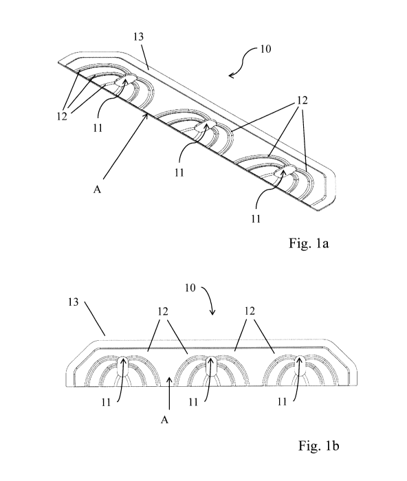
Fig. la: shows a first embodiment of a moulding for use in an
electrochemical module, in perspective view;
Fig. lb: shows the moulding of Fig. 1a in plan view; and
Fig. 1c: shows the moulding of Fig. la in a side view;
Fig. 2a: shows a stack with three electrochemical modules according to
the prior art, without inventive mouldings, in cross section;
Fig. 2b: shows a stack with three electrochemical modules each having a
moulding as per Fig. 1a, in cross section;
Fig. 2c: shows an electrochemical module from Fig. 2b with a moulding as
per Fig. 1a in an exploded view (here it should be borne in mind
that in comparison to the modules in Fig. 2a and Fig. 2b, the
electrochemical module in Fig. 2c is shown turned on its head for
better visibility of the channels);
Fig. 3a: shows a second embodiment of a moulding for use in an
electrochemical module, in perspective view; and
CA 03055588 2019-09-06
Fig. 3b: shows the moulding of Fig. 3a in plan view.
Fig. la shows, in perspective representation, a first embodiment of the
moulding (10) for use in an electrochemical module (20). The arrangement of
5 the moulding (10) within the electrochemical module (20) is shown in Fig.
2b
and Fig. 2c. Fig. lb shows the moulding (10) in plan view, and it is shown in
Fig. lc in a side view from the side (A), which in the arrangement in the
electrochemical module (20) is facing the interior of the process gas space.
The
moulding (10) has been produced by powder metallurgy and is therefore
10 porous. The moulding is flat and possesses a flat body with one plane of
principal
extent. It has a plurality of gas passage openings (11) - in the variant
depicted, three
central gas passage openings (11) - through which the process gas is supplied
and,
respectively, removed in the operation of the electrochemical module. Channels
(12) extend in a star shape from each of the gas passage openings up to the
15 side edge (A) of the moulding, which in the arrangement in the
electrochemical
module is facing the inner process gas space of the electrochemical module.
Channels which branch off from the gas passage opening (11) originally in a
direction remote from the inner process gas space are redirected here in an
arc
shape to the side edge (A) in the direction of inner process gas space. The
individual channels (12) extend continuously from the gas passage opening to
the side edge (A), thereby enabling efficient gas steering and a low pressure
drop within the process gas conduction space.
Additionally, from the gas passage opening (11) in the direction of the side
edge
(A), the moulding (10) has a gas-permeable, open-pored structure (in other
words, gas exchange between individual adjacent pores is possible). At the
other side edges, the moulding is pressed together (13) and in these
directions
is therefore impermeable to gas.
In operation of the electrochemical module, the process gas flows from the gas
passage openings (11) through the channels (12) and the pores to the side
edge (A) of the moulding, from which it flows on into the interior process gas
space. The flow of gas may also be in the opposite direction.
The number and geometry of the channels are optimized to maximize uniformity
of supply to the inner process gas space. For this purpose, at the side edge
(A),
the distances between adjacent channels are approximately equal, and when
. CA 03055588 2019-09-06
16
they open out, therefore, the channels are distributed uniformly over the side
edge. Moreover, in the present exemplary embodiment, the channels at the side
edge (A) open out approximately at right angles; in this region, therefore,
the
channels run substantially parallel to one another locally.
As can be seen from Fig. 1c, the channels are made superficially and vary in
their cross-sectional area. The cross-sectional area of a channel is
substantially
constant over its length, but is selected to be larger in line with the length
of the
channel from the gas passage opening (11) up to the side edge (A). This as
well is a measure for achieving maximum uniformity of flow to and removal from
the distribution structures of the interconnector in the interior of the
process gas
space.
Fig. 2a shows a stack with three electrochemical modules according to the
prior
art, without the inventive moulding. The arrangement of the moulding in an
electrochemical module (20) is shown in Fig. 2b and Fig. 2c. Fig. 2a and Fig.
2b
each show, in a schematic representation, a cross section through a stack (30)
with three electrochemical modules (20) stacked on top of one another. The
electrochemical modules (20) each have an electrochemical cell unit (21) which
consists of a porous, metallic support substrate (22) which has been produced
by powder metallurgy, with a layer construction (23) with at least one
electrochemically active layer applied on this substrate (22) in a gas-
permeable
region. The support substrate (22) with the layer construction (23) is pressed
together in a gastight manner at the edge and has a plate-shaped base
structure which in variant embodiments, for enlargement of surface area, may
also have local curvature - for example, a wave-shaped design - over a smaller
length scale. Located on the side of the support substrate (22) that is
opposite
the layer construction there is in each case an interconnector (24), which in
the
region where it bears against the support substrate (22) has a rib structure
(24a). The longitudinal direction of the rib structure runs here in the cross-
sectional plane in Fig. 2a and Fig. 2b. The interconnector (24) extends beyond
the region of the electrochemical cell unit (21) and bears at its outer edge
against a frame panel (25) circumscribing the electrochemical cell unit. The
,
circumscriptive frame panel (25) is joined in gastight fashion to the
electrochemical cell unit (21) at the inner edge, and is joined in gastight
fashion
CA 03055588 2019-09-06
17
to the interconnector (24) at the outer edge, via a circumscriptive welded
connection. The frame panel (25) and the interconnector (24) thus form a
constituent of a metallic, gastight housing which, with the electrochemical
cell
unit (21), delimits a gastight process gas space (26). The process gas
conduction space (27) is a sub-space of the process gas space (26), and
extends over the region outside the region of the electrochemical cell unit
(21),
and is open in the direction of the electrochemical cell unit (21). In the
region of
the process gas conduction space there are gas passage openings (28) formed
in the housing (frame panel and interconnector) for the supplying and/or
removal of the process gases (not shown in Fig. 2a and Fig. 2b, since the
section is taken to the side of the gas passage openings). The gas passage
openings in the housing (28) and the gas passage openings (11) in the
moulding are aligned with one another. The conducting of gas within the stack
takes place in a vertical direction (stack direction of the stack (B)) by
means of
corresponding channel structures, which are formed in the region of the gas
passage openings customarily by means of separate inlays (29), seals, and
also by controlled application of sealant (e.g. glass solder). The channel
structures thus sealed connect the process gas conduction spaces of adjacent
electrochemical modules, in a vertical direction.
Whereas Fig. 2a depicts the state of the art without moulding, Fig. 2b and
Fig. 2c show the arrangement of the moulding according to Fig. la within the
process gas conduction space (27) of the electrochemical module (20). It
should be borne in mind that in Fig. 2c, in comparison to the modules in Fig.
2a
and Fig. 2b, the electrochemical module is shown turned on its head for better
visibility of the channels (12). The shape of the moulding is adapted to the
interior of the process gas conduction space. The moulding bears by its
topside
against the frame panel (25), the upper boundary of the process gas conduction
space, and by its bottom side against the interconnector (24), the lower
boundary of the process gas conduction space. A flat contact is advantageous
in each case, at its topside and/or at its bottom side. It thickness therefore
corresponds to the space internal height of the process gas conduction space
(27). The channels (12) formed superficially are located on the underside of
the
moulding (10) (in Fig. 2c, the moulding is shown turned on its head). As well
as
CA 03055588 2019-09-06
18
the gas guide function in the process gas conduction space, the moulding takes
on an important mechanical function. It serves to support the housing along
the
stack direction of the stack (B), so that compression of the housing edge
region
is prevented when a pressing pressure is applied. Additionally, because of the
flat architecture of the moulding, the flexural and torsional stiffness of the
housing edge region, which consists of a thin frame panel (25) and a thin
interconnector (24), is decisively increased and hence the risk of cracking in
the
weld seams under mechanical loading is reduced. In one advantageous variant
embodiment, the moulding is spot welded on the housing and fixed accordingly.
The mouldings (10,10') used for supplying and for removing the process gases
are preferably different. Their properties (material, shape, porosity,
geometry of
the channel structures, etc.) may be optimized independently of one another
for
their intended use.
Fig. 3a shows, schematically, a perspective view, and Fig. 3b the plan view,
of a
further variant embodiment of the moulding. In this variant embodiment, the
individual gas passage openings (11) of the moulding are in communication
with one another through additional channels. This channel structure
contributes to additional gas equalization.