Note: Descriptions are shown in the official language in which they were submitted.
IDENTIFICATION OF MATERIAL TYPE AND CONDITION IN A
DRY BULK MATERIAL STORAGE BIN
BACKGROUND
[0001] The exemplary embodiments described herein relate to optical
analysis systems and methods for measuring characteristics of a dry bulk
material
or powder. More particularly, embodiments disclosed herein relate to systems
and
methods for measuring the characteristics of a bulk material or powder and use
the
measurements to ensure that the bulk material or powder is not contaminated.
[0002] Some industrial applications that use bulk materials and powders
include forming set cement compositions for the construction industry. The oil
and
gas industry also uses set cement compositions for stabilizing and plugging
wellbores, among other purposes. The operational parameters relating to cement
slurries and the characteristics of the resultant set cement derive, at least
in part,
from the dry cement composition and the composition and concentration of the
optional cement slurry additives mixed as powders in the dry cement blend
composition.
[0003] Accordingly, while storing and conveying raw materials used in a
blend to form dry cements it is desirable to have a correct determination of
the raw
materials used and their physical and chemical condition during storage and
transfer. It is also desirable to determine flow conditions in a conveying
system to
optimize energy costs and to avoid damage to the infrastructure for handling
the
materials. Current techniques include discrete measurements in storage
containers
and pipelines at specific locations and times including manual sampling and
laboratory testing the materials. For
example, some embodiments include
collecting a manual sample from a port located in the cone of a storage bin.
However, samples taken from this port provide information about the material
contained in the area of the bin adjacent to the sampling port and not the
rest of
the bin. Further approaches include inserting probes into the material
contained in
sample bins and hoppers from the top of the container. When using a long
probe,
this method may provide information of different type of material throughout
the
tank, but not of the condition of the material. Moreover, inserting probes
requires
carrying tools to the top of the container and back to the ground, and having
a user
1
CA 3055593 2019-09-13
standing at height for doing the work, incurring in work place liability and
time-
consuming steps.
[0004] Other techniques involve imprecise and unreliable methods such as
detecting the sound that the raw material makes as it travels through the
pipelines.
Other approaches include analyzing the discharge of the raw material at the
end or
at some intermediate point of the pipeline. These measurement techniques
typically involve a complicated, multi-step process of mixing harsh chemicals
with
the bulk materials or powders and analyzing the products via expensive, time-
consuming methods like x-ray diffraction, gravinnetric analysis, slurrying and
testing
viscosity over time in specified temperature and pressure conditions, and the
like.
Moreover, these measurement techniques may be insufficient for taking remedial
action when an error occurs with one or more of the material supplies and an
entire
batch of dry cement is lost or deployed on location without satisfying quality
standards. In relation to downhole oil and gas operations, improperly deployed
cementing operations can increase both costs and liabilities, including costly
remedial operations to repair the set cement.
SUMMARY
[0005] In accordance with a general aspect, there is provided a method
comprising: optically interacting a bulk material or powder stored in a
storage bin
with an integrated computational element ("ICE") configured to modify an
electromagnetic radiation according to a characteristic of the bulk material
or
powder; detecting the modified electromagnetic radiation with a detector;
producing an output signal with a signal processor, the output signal being
correlated to the characteristic of the bulk material or powder; determining
whether
the bulk material or powder is suitable for continued storage in the storage
bin; and
transmitting an alert when it is determined that the bulk material or powder
is not
suitable for continued storage or usage, wherein the bulk material or powder
comprises at least one of a dry cement or a dry cement component.
[0006] In accordance with another aspect, there is provided a device
comprising: a processor circuit; and a memory circuit storing commands, which
2
CA 3055593 2019-09-13
when executed by the processor circuit cause the device to perform a method
comprising: receiving a first signal from a first optical computing device at
a first
location in a system for storing and conveying materials; receiving a second
signal
from a second optical computing device at a second location in the system for
storing and conveying materials, wherein at least one of the first and second
signal
result from an electromagnetic radiation interacted with a dry cement
component
stored in a storage bin, and at least one of the first and second signals
results from
an electromagnetic radiation modified by an Integrated Computational Element
(ICE) according to a characteristic of the dry cement; determining a
characteristic
of the dry cement component; determining, based on the characteristic of the
dry
cement component, whether the dry cement component is suitable for continued
storage; and transmitting a message flagging the storage bin when it is
determined
that the dry cement component is not suitable for continued storage.
[0007] In accordance with a further aspect, there is provided a method
comprising: receiving an output signal from each of a plurality of optical
computing
devices disposed in separate locations in a storage bin comprising a bulk
material
or powder; processing each of the output signals from the plurality of optical
computing devices with a signal processor; determining a characteristic of the
bulk
material or powder based on the processing of the output signals; and
transmitting
an alert when it is determined that the bulk material or powder is not
suitable for
continued storage.
[0008] In accordance with as still further aspect, there is provided a device
comprising: a processor circuit; and a memory circuit storing commands, which
when executed by the processor circuit cause the device to: receive an output
signal from each of a plurality of optical computing devices disposed in
separate
locations in a system for storing and transporting a bulk material or powder;
process each of the output signals from the plurality of optical computing
devices
with a signal processor; determine a characteristic of the bulk material or
powder
based on the processing of the output signals; and transmit an alert when it
is
determined that the bulk material or powder is not suitable for continued
storage or
transport.
3
CA 3055593 2019-09-13
BRIEF DESCRIPTION OF THE DRAWINGS
[0009] The following figures are included to illustrate certain aspects of the
exemplary embodiments described herein, and should not be viewed as exclusive
embodiments.
The subject matter disclosed is capable of considerable
modifications, alterations, combinations, and equivalents in form and
function, as
will occur to those skilled in the art and having the benefit of this
disclosure.
[0010] FIG. 1 illustrates an exemplary integrated computational element
(ICE), according to one or more embodiments.
[0011] FIG. 2 illustrates a block diagram non-mechanistically illustrating
how an optical computing device distinguishes electromagnetic radiation
related to
a characteristic of interest from other electromagnetic radiation, according
to some
embodiments.
[0012] FIG. 3 illustrates an exemplary system for monitoring a dry cement
present in a container, according to some embodiments.
[0013] FIG. 4 illustrates an exemplary housing used to house an optical
computing device, according to some embodiments.
[0014] FIG. 5 illustrates a system for storing and conveying raw materials
from storage containers to transportation units including an optical analysis
system,
according to some embodiments.
[0015] FIG. 6 illustrates a storage bin including optical analysis systems to
identify material type and condition of a bulk material or powder, according
to some
embodiments.
[0016] FIG. 7 illustrates a flowchart including steps in a method for
identification of material type and condition in a bulk material or powder
storage
bin, according to some embodiments.
DETAILED DESCRIPTION
[0017] The exemplary embodiments described herein relate to optical
analysis systems and methods for monitoring bulk materials or powders and, in
particular, to systems and methods for determining the characteristics and
condition of bulk materials or powders. Methods and systems consistent with
the
present disclosure are able to characterize the flow by "seeing" the bulk
materials
or powders as they are stored for use in a conveying and blending system in
real
4
CA 3055593 2019-09-13
time. Accordingly, methods and systems consistent with the present disclosure
enable adjustment of conveying and blending procedures based on the
characteristics of the stored bulk materials or powders.
[0018] Many industrial applications commonly use dry bulk materials and
powders.
For example, the agro-industry, the food industry, and the
pharmaceutical industry process large amounts of grains, powders, liquids and
small unit sizes (fruits such as grapes, raisins, and nuts, medications in the
form of
pills) for storage, packaging, and distribution. Industrial applications of
dry bulk
materials or powders include storing separated raw materials under dry
conditions
prior to mixing and preparation for use.
Industrial applications of dry bulk
materials typically include systems and methods to store the raw materials in
separate containers for each raw material and conveying mechanisms to
transport
the raw materials from storage containers to a scale tank and from the scale
tank
to a shipping location, or a deployment location. At each of the storage and
conveying stages, it is desirable to have a precise knowledge of the type and
physical condition of the material handled. Some of the characteristics that
are
relevant in many applications include powder particle size, moisture content,
homogeneity of a mixture, and flow conditions in a conveying system.
[0019] The oil and gas industry uses bulk materials and powders for
making cement blends deployed, for example, to plug boreholes or secure casing
strings therein. Some of these cementing projects may be quite challenging, as
it
may be desirable to convey a cement composition beyond the ocean floor,
several
thousand feet underneath the water surface. Accordingly, it is desirable to
verify
the correct dry cement blend prior to deploying the cement in the field. The
oil and
gas industry uses many types of cements according to different desirable
characteristics for specific applications. In some instances, dry cements
include any
one of the raw materials used in Portland cements, gypsum cements, hydraulic
cements and Sorel cements. Other dry materials besides dry cement typically
used
in the oil and gas industry include salt, lime, sand, POZMIX , and the like.
An
accurate account of the identity and condition of the raw materials used to
prepare
the cement mix during storage and conveying of the raw materials is therefore
highly desirable. In some instances, the physical condition is relevant to
reactivity
5
CA 3055593 2019-09-13
of the raw material in cement slurries. For example, fines (reduced size
particles)
react differently from coarser particles of the same material.
Moreover, coarse
materials have a tendency to settle and deposit in storage containers and
transfer
tubes before arriving to the desired destination, reducing material transfer
efficiency. Furthermore, blending conditions may change in time, and thus it
is
desirable to have a sense of the condition of the bulk material or powder
being used
in real time, and adapt the blending methodology accordingly.
[0020] Current attempts to obtain information about bulk material or
powder identity and condition include sample extraction and analysis on a
periodical
basis at multiple locations. These methods can be time consuming and discrete
in
nature, providing partial and extemporaneous information that may not be
sufficient for a timely remedial action. Thus, when an error occurs in the
supply
logistics and the wrong material is used, or pipeline corrosion contaminates
the
sample or the mixture, or an air pump or compressor leaks moisture into the
system, an entire batch of the mix may be compromised. This may result in the
loss of the batch or in a worst-case scenario, more serious damage can occur
when
the wrong batch deploys to the field.
Such may be the situation when a
compromised cement mix is used in structural engineering, such as plugging or
lining a wellbore extending from the sea bed, thousands of feet under water.
[0021] The exemplary systems and methods described herein employ
various configurations of optical computing devices, also commonly referred to
as
"opticoanalytical devices," for the rapid analysis of dry cements. The
disclosed
systems and methods may be suitable for use in the oil and gas industry since
the
described optical computing devices provide a cost-effective, rugged, and
accurate
means for identifying bulk materials and powders in order to facilitate the
effective
production of cement slurries and set cements in oil/gas applications. The
various
disclosed systems and methods are equally applicable to other technology
fields.
For example, the food and drug industry, industrial applications, and mining
industries, will benefit from embodiments consistent with the present
disclosure.
More generally, any field where it may be advantageous to determine in real-
time
or near real-time a characteristic of a dry composition, especially to
determine the
6
CA 3055593 2019-09-13
quality of the dry composition and of each of its components, will benefit
from
embodiments consistent with the present disclosure.
[0022] The optical computing devices disclosed herein, which are described
in more detail below, can advantageously provide rapid analysis of at least
one
characteristic of a dry cement (e.g., the composition of individual components
in
the dry cement or the particle size distribution in the dry cement). As
described
above, such a detailed analysis currently requires extensive time, high cost,
and
harsh chemicals and can give unreliable results. By contrast, the optical
computing
devices disclosed herein may provide rapid analysis of dry cements with
minimal
sample prep, if any. Additionally, because the analysis is rapid, multiple
measurements may be obtained to reduce error. Further, because of the small
size
and relatively low cost of the optical computing devices disclosed herein, the
methods for analyzing dry cements are suitable not only for laboratory use,
but
also, in-field analysis (e.g., at a manufacturing or mining site, at a
distribution
center, or at a well site).
[0023] A significant and distinct advantage of the optical computing
devices disclosed herein is that they can be configured to specifically detect
and/or
measure a particular characteristic of interest of a dry cement, thereby
allowing
qualitative and/or quantitative analyses of the material of interest to occur
without
having to undertake a time-consuming sample processing procedure. With rapid
analyses capabilities on hand, the exemplary systems and methods described
herein may be able to determine the identity and flow characteristics of raw
materials used to form dry cement compositions.
[0024] As used herein, the term "dry cement" refers to a mixture of solid
particles including at least some cement particles and is not hydrated beyond
ambient conditions (e.g., no additional water has been added). It should be
noted
that the term "dry cement" does not refer to set cements (e.g., that have been
formed from a cement slurry).
[0025] Dry cements may comprise a single cement or comprise a blend of
two or more cements. Examples of dry cements may include, but are not limited
to, hydraulic cements, Portland cement, gypsum cements, pozzolan cements,
calcium phosphate cements, high alumina content cements, silica cements, high
7
CA 3055593 2019-09-13
alkalinity cements, shale cements, acid/base cements, magnesia cements (e.g.,
Sorel cements), zeolite cement systems, cement kiln dust cement systems, slag
cements, micro-fine cements, bentonites, and the like, any derivative thereof,
and
any combination thereof. Examples of Portland cements may include, but are not
.. limited to, Portland cements classified as Classes A, C, H, and G according
to API
and their equivalent, Ordinary Portland cements of Type I, I/II, III, and V
according
to ASTM, including combinations thereof. Examples of pozzolan cements may
include, but are not limited to, fly ash, silica fume, granulated blast
furnace slag,
calcined shale, opaline shale, pumice, pumicite, diatomaceous earth, volcanic
ash,
tuft, cement kiln dust, and any combination thereof.
[0026] As used herein, the term "characteristic" refers to a chemical,
mechanical, or physical property (quantitative or qualitative) of a material
of
interest (e.g., a dry cement or an analyte thereof). As used herein, the term
"analyte" refers to a chemical component. The term analyte encompasses
chemical
components that are at least one of: present in the material of interest, may
be
added to the material of interest, involved in a chemical reaction (e.g.,
reagents
and products) transpiring within the material of interest, and not involved in
a
chemical reaction transpiring within the material of interest.
Illustrative
characteristics of a material of interest that can be monitored with the
optical
computing devices disclosed herein can include, for example, chemical
composition
(e.g., identity and concentration in total or of individual analytes),
contaminant
content, pH, viscosity, density, ionic strength, salt content, porosity,
opacity,
bacteria content, particle size distribution, color, temperature, hydration
level,
oxidation state, and the like. Moreover, the phrase "characteristic of
interest" may
be used herein to refer to a characteristic of a material of interest.
[0027] Examples of analytes within a dry cement may include, but are not
limited to, SiO2, Al2O3, FeO, Fe2O3, CaO, Na2O, K20, MgO, SO3, Mn203, T102,
P205,
SnO, Sr0, (Ca0)3 = SiO2, (CaO)2 = SiO2, (CaO)3 = A1203, (CaO)3 = A1203 =
Fe2O3,
CaSO4 = H20, SO3, Ca(OH)2,
H4SiO4, free lime, inorganic salts (e.g.,
sodium, potassium, magnesium, and calcium salts of sulfate, phosphate, and
carbonate), metal containing compounds (e.g., bromide, chloride, nitrate,
sulfate,
and phosphate salts of cadmium, zinc, nickel, copper, lead, and the like,
metal
8
CA 3055593 2019-09-13
oxides of such metals, and the like), hydroxides, water, and any combination
thereof.
[0028] In some instances, the foregoing analytes may be used in
classifying cements (i.e., as a major component) or as grading cements (i.e.,
as a
minor components), which depends on the dry cement. As used herein, the "major
component" of a dry cement refers to a component or analyte that identifies
the
type of dry cement (e.g., Portland cement versus Sorel cement or Type I
Portland
cement versus Type V Portland cement). As used herein, the "minor component"
of
a dry cement refers to a component or analyte that is not a major component.
The
terms "major component" and "minor component" do not necessarily relate to a
concentration. For example, in Ordinary Grade, Class G Portland cement may
have
about 5% Ca03 A1203 as one of the major components and up to about 6% MgO
as one of the minor components.
[0029] As used herein, the term "cement slurry additive" refers to an
additive that can be included in a cement slurry with water and a dry cement.
Cement slurry additives may be liquids or dry additives (e.g., powders). In
some
instances, the dry cement and at least one cement slurry additive (typically a
dry
additive) may be combined to form a mixture that can be used in preparing a
cement slurry. The mixture may be prepared at a storage facility,
manufacturing
facility, laboratory, distribution center, at the well site, or in transit
between any of
these locations.
[0030] Examples of cement slurry additives may include, but are not
limited to, set retarders, set accelerators, fillers (e.g., weighting agents,
lightweight
particles like glass beads, rubber particles, and the like), dispersants,
gelling
agents, and the like, and any combination thereof.
[0031] As used herein, the term "electromagnetic radiation" refers to radio
waves, microwave radiation, infrared and near-infrared radiation, visible
light,
ultraviolet light, X-ray radiation and gamma ray radiation.
[0032] As used herein, the term "optical computing device" refers to an
optical device that receives an input of electromagnetic radiation from a
substance
or sample of the substance, and produces an output of electromagnetic
radiation
from a processing element arranged within the optical computing device. The
9
CA 3055593 2019-09-13
processing element may be, for example, an integrated computational element
(ICE) used in the optical computing device. As discussed in detail below, the
ICE
optically interacts and changes the electromagnetic radiation incident on a
detector
such that an output of the detector can be correlated to at least one
characteristic
of the substance being measured or monitored. The output of electromagnetic
radiation from the processing element can be reflected electromagnetic
radiation,
transmitted electromagnetic radiation, and/or dispersed electromagnetic
radiation.
Whether the detector analyzes reflected or transmitted electromagnetic
radiation
may depend on the structural parameters of the optical computing device as
well as
other considerations known to those skilled in the art. In addition, emission
and/or
scattering by the substance, for example via fluorescence, luminescence, Raman
scattering, and/or Raleigh scattering, can also be monitored by the optical
computing devices.
[0033] As used herein, the term "optically interact" or variations thereof
refers to the reflection, transmission, scattering, diffraction, or absorption
of
electromagnetic radiation either on, through, or from one or more processing
elements (i.e., integrated computational elements). Accordingly, optically
interacted light refers to electromagnetic radiation that has been reflected,
transmitted, scattered, diffracted, or absorbed by, emitted, or re-radiated,
for
example, using the integrated computational elements, but may also apply to
interaction with a dry cement.
[0034] The exemplary systems and methods described herein will include
at least one optical computing device configured to measure at least one
characteristic of a dry cement or analyte thereof. In some embodiments, the
optical computing devices suitable for use in the exemplary embodiments
described
herein may be mobile or portable. In some embodiments, the optical computing
devices suitable for use in the exemplary embodiments described herein may be
a
portion of tank, silo, vat, pipeline, tube, or the like that store, mix,
transfer or
otherwise contain or transport dry cement (e.g., within a wall).
[0035] The presently described optical computing devices combine the
advantage of the power, precision, and accuracy associated with laboratory
spectrometers, while being extremely rugged and suitable for field use.
CA 3055593 2019-09-13
Furthermore, the optical computing devices can perform calculations in real-
time or
near real-time without the need for time-consuming sample processing. In this
regard, in some embodiments the optical computing devices detect and analyze
particular characteristics of interest.
As a result, interfering signals are
discriminated from those of interest by appropriate configuration of the
optical
computing devices, such that the optical computing devices provide a rapid
response regarding the characteristic of interest as based on the detected
output.
In some embodiments, the detected output is a voltage indicative of the
magnitude
of the characteristic of interest. The foregoing advantages and others make
the
optical computing devices particularly well suited for field use.
[0036] In some embodiments, the optical computing devices detect not
only the composition and concentrations of an analyte in a material of
interest, but
also determine physical properties and other characteristics of the material
of
interest as well, based on their analysis of the electromagnetic radiation
received
.. from the substance. For example, the optical computing devices can
determine the
concentration of an analyte and correlate the determined concentration to a
characteristic of the material of interest by using suitable processing means.
In
some embodiments, optical computing devices as disclosed herein provide a
measurement of a granularity of a powder sample, or an average particle size
in
the powder sample. As will be appreciated, the optical computing devices can
detect as many characteristics as desired for a given material of interest.
All that is
required to accomplish the monitoring of multiple characteristics of interest
is the
incorporation of suitable processing and detection means within the optical
computing device for each characteristic of interest (e.g., the concentration
of an
analyte, the particle size distribution, or the temperature). Another property
of a
dry cement that can be measured may be the particle size of the different
components in the cement.
[0037] In some embodiments, the properties of the material of interest
can be determined using a combination of characteristics of interest (e.g., a
linear,
.. non-linear, logarithmic, and/or exponential combination). Accordingly, the
more
characteristics detected and analyzed using the optical computing devices, the
more accurately the properties of the material of interest will be determined.
For
11
CA 3055593 2019-09-13
example, properties of a dry cement that may be determined using optical
computing devices described herein may include, but are not limited to, the
absolute concentration of an analyte, the relative ratios of two or more
analytes,
the presence or absence of an analyte, and the like, and any combination
thereof.
[0038] Optical computing devices as described herein utilize
electromagnetic radiation to perform calculations, as opposed to the hardwired
circuits of conventional electronic processors. When electromagnetic radiation
interacts with a material of interest, unique physical and chemical
information
about the material of interest may be encoded in the electromagnetic radiation
that
is reflected from, transmitted through, or radiated from the material of
interest.
This information is the spectral "fingerprint" of the material of interest.
The optical
computing devices described herein are capable of extracting the information
of the
spectral fingerprint of multiple characteristics of a material of interest
(e.g., a dry
cement blend or an analyte thereof), and converting that information into a
detectable output regarding the overall properties of the monitored material
of
interest. That is, through suitable configurations of the optical computing
devices,
electromagnetic radiation associated with characteristics of interest can be
separated from electromagnetic radiation associated with all other components
of
the material of interest in order to estimate the properties (e.g.,
reactivity) of the
monitored substance (e.g., a dry cement blend or an analyte thereof) in real-
time
or near real-time.
[0039] Each of the ICEs used in the exemplary optical computing devices
described herein is capable of distinguishing electromagnetic radiation
related to
the characteristic of interest from electromagnetic radiation related to other
components of a dry cement blend.
[0040] A method according to some embodiments includes optically
interacting a bulk material or powder stored in a storage bin with an
integrated
computational element ICE configured to modify an electromagnetic radiation
according to a characteristic of the bulk material or powder. The method also
includes detecting the modified electromagnetic radiation with a detector, and
producing an output signal with a signal processor. The output signal is
correlated
with the characteristic of the bulk material or powder. The method further
12
CA 3055593 2019-09-13
comprises determining whether the bulk material or powder is suitable for
continued storage in the storage bin. In some embodiments, the method includes
transmitting an alert when it is determined that the bulk material or powder
is not
suitable for continued storage. The bulk material or powder comprises at least
one
of a dry cement, a dry cement component, or an analyte of interest. Bulk
materials
or powders as disclosed herein may include not only dry cement, but also may
include dry barite powders and blends used for drilling fluids. More
generally, bulk
materials or powders as disclosed herein include dry powders and blends such
as
fertilizers, pharmaceuticals and agro-industrial products.
[0041] A device according to some embodiments includes a processor
circuit and a memory circuit storing commands. When executed by the processor
circuit the commands cause the device to perform a method including receiving
a
first signal from a first optical computing device at a first location in a
system for
storing and conveying materials. The commands also cause the device to perform
the step of receiving a second signal from a second optical computing device
at a
second location in the system for storing and conveying materials. In some
embodiments, the first and second signals result from an electromagnetic
radiation
interacted with a dry cement component stored in a storage bin, and at least
one of
the first and second signals results from an electromagnetic radiation
modified by
an Integrated Computational Element (ICE) according to a characteristic of the
dry
cement. The commands also cause the device to perform the steps of determining
a characteristic of the dry cement component and determining, based on the
characteristic of the dry cement component, whether the dry cement component
is
suitable for continued storage. In some embodiments, the commands also cause
the device to transmit a message flagging the storage bin when it is
determined
that the dry cement component is not suitable for continued storage.
[0042] A method according to the present disclosure includes receiving an
output signal from each of a plurality of optical computing devices disposed
in
separate locations in a storage bin comprising a stored bulk material or
powder and
processing each of the output signals from the plurality of optical computing
devices with a signal processor. The method also includes determining a
characteristic of the stored bulk material or powder based on the processing
of the
13
CA 3055593 2019-09-13
output signals, and transmitting an alert when it is determined that the bulk
material or powder is not suitable for continued storage.
[0043] FIG. 1 illustrates an exemplary ICE 100 suitable for use in the
optical computing devices used in systems and methods described herein. As
illustrated, ICE 100 may include a plurality of alternating layers 102 and
104, such
as silicon (Si) and SiO2 (quartz), respectively. In general, these layers 102,
104
consist of materials whose index of refraction is high and low, respectively.
Other
examples might include niobia and niobium, germanium and germania, MgF, SiOx,
and other high and low index materials known in the art. An optical substrate
106
provides support to layers 102, 104, according to some embodiments. In some
embodiments, optical substrate 106 is BK-7 optical glass. In other
embodiments,
optical substrate 106 may be another type of optical substrate, such as
quartz,
sapphire, silicon, germanium, zinc selenide, zinc sulfide, or various plastics
such as
polycarbonate, polymethylmethacrylate (PMMA), polyvinylchloride (PVC),
diamond,
ceramics, combinations thereof, and the like.
[0044] At the opposite end (e.g., opposite optical substrate 106 in FIG. 1),
ICE 100 may include a layer 108 that is generally exposed to the environment
of
the device or installation. The number of layers 102, 104 and the thickness of
each
layer 102, 104 are determined from the spectral attributes acquired from a
spectroscopic analysis of a characteristic of interest using a conventional
spectroscopic instrument. The spectrum of interest of a given characteristic
of
interest typically includes any number of different wavelengths. The exemplary
ICE
100 in FIG. 1 does not in fact represent any particular characteristic of
interest, but
is provided for purposes of illustration only. Consequently, the number of
layers
102, 104 and their relative thicknesses, as shown in FIG. 1, bear no
correlation to
any particular characteristic of interest. Nor are layers 102, 104 and their
relative
thicknesses necessarily drawn to scale, and therefore should not be considered
limiting of the present disclosure. Moreover, those skilled in the art will
readily
recognize that the materials that make up each layer 102, 104 (i.e., Si and
SiO2)
may vary, depending on the application, cost of materials, and/or
applicability of
the materials to the monitored substance.
14
CA 3055593 2019-09-13
[0045] In some embodiments, the material of each layer 102, 104 can be
doped or two or more materials can be combined in a manner to achieve the
desired optical characteristic. In addition to solids, ICE 100 may also
contain
liquids and/or gases, optionally in combination with solids, in order to
produce a
desired optical characteristic. In the case of gases and liquids, ICE 100 can
contain
a corresponding vessel (not shown), which houses gases or liquids. Exemplary
variations of ICE 100 may also include holographic optical elements, gratings,
piezoelectric, light pipe, digital light pipe (DLP), variable optical
attenuators, and/or
acousto-optic elements that, for example, can create transmission, reflection,
and/or absorptive properties of interest.
[0046] Layers 102, 104 exhibit different refractive indices. By properly
selecting the materials of layers 102, 104, their relative thicknesses and
spacing
ICE 100 may be configured to selectively pass/reflect/refract predetermined
fractions of electromagnetic radiation at different wavelengths. Each
wavelength is
given a predetermined weighting or loading factor. The thickness and spacing
of
layers 102, 104 may be determined using a variety of approximation methods
from
the spectrograph of the characteristic of interest. These methods may include
inverse Fourier transform (IFT) of the optical transmission spectrum and
structuring
ICE 100 as the physical representation of the IFT. The approximations convert
the
IFT into a structure based on known materials with constant refractive
indices.
[0047] The weightings that layers 102, 104 of ICE 100 apply at each
wavelength are set to the regression weightings described with respect to a
known
equation, or data, or spectral signature. Briefly, ICE 100 may be configured
to
perform the dot product of the input light beam into ICE 100 and a desired
loaded
regression vector represented by each layer 102, 104 for each wavelength. As a
result, the output light intensity of ICE 100 is related to the characteristic
of
interest.
[0048] FIG. 2 illustrates a block diagram that non-mechanistically
illustrates how an optical computing device 200 is able to distinguish
electromagnetic radiation related to a characteristic of interest from other
electromagnetic radiation. As shown in FIG. 2, illumination by incident
electromagnetic radiation induces an output of electromagnetic radiation from
a
CA 3055593 2019-09-13
bulk material or powder 202 (e.g., sample-interacted light), some of which is
electromagnetic radiation 204 corresponding to the characteristic of interest
and
some of which is background electromagnetic radiation 206 corresponding to
other
characteristics of the bulk material or powder 202. In some embodiments, bulk
material or powder 202 may include one or more characteristics of interest
that
may correspond to the one or more analytes of bulk material or powder 202.
[0049] Although not specifically shown, one or more processing elements
may be employed in the optical computing device 200 in order to restrict the
optical
wavelengths and/or bandwidths of the system and thereby eliminate unwanted
electromagnetic radiation existing in wavelength regions that have no
importance.
Such processing elements can be located anywhere along the optical train, such
as
directly after a light source, which provides the initial electromagnetic
radiation.
[0050] Beams of electromagnetic radiation 204 and 206 impinge upon the
optical computing device 200, which contains an exemplary ICE 208 therein. In
the
illustrated embodiment ICE 208 may produce optically interacted light, for
example,
transmitted optically interacted light 210, and reflected optically interacted
light
214. In operation, ICE 208 may be configured to distinguish electromagnetic
radiation 204 from background electromagnetic radiation 206.
[0051] Transmitted optically interacted light 210, which may be related to
the characteristic of interest of the bulk material or powder 202, may be
conveyed
to a detector 212 for analysis and quantification. In some embodiments,
detector
212 produces an output signal in the form of a voltage that corresponds to the
particular characteristic of bulk material or powder 202.
In at least one
embodiment, the signal produced by detector 212 and the characteristic of bulk
material or powder 202 (e.g., concentration of an analyte, or flow speed) may
be
directly proportional. In other embodiments, the relationship may be a
polynomial
function, an exponential function, and/or a logarithmic function. The
reflected
optically interacted light 214 may be related to other characteristics of the
bulk
material or powder 202, and can be directed away from detector 212. In
alternative configurations, ICE 208 is such that reflected optically
interacted light
214 relates to the characteristic of interest, and the transmitted optically
interacted
light 210 relates to other characteristics in the bulk material or powder 202.
16
CA 3055593 2019-09-13
[0052] In some embodiments, a second detector 216 can be present and
arranged to detect the reflected optically interacted light 214.
In other
embodiments, second detector 216 may be arranged to detect electromagnetic
radiation 204 and 206 derived from the bulk material or powder 202 or
electromagnetic radiation directed toward or before the bulk material or
powder
202. Without limitation, second detector 216 may be used to detect radiating
deviations stemming from an electromagnetic radiation source (not shown),
which
provides the electromagnetic radiation (i.e., light) to the device 200. For
example,
radiating deviations can include such things as, but not limited to, intensity
fluctuations in the electromagnetic radiation, interference fluctuations
(e.g., dust or
other interferences passing in front of the electromagnetic radiation source),
coatings on windows included with optical computing device 200, combinations
thereof, or the like. In some embodiments, a beam splitter (not shown) splits
electromagnetic radiation 204 and 206, and the transmitted or reflected
electromagnetic radiation can then be directed to two or more ICEs 208. That
is, in
such embodiments, the transmitted or reflected electromagnetic radiation
passes
through ICE 208, which performs the computation before it travels to detector
212.
[0053] The characteristic(s) of interest being analyzed using optical
computing device 200 can be further processed and/or analyzed computationally
to
provide additional characterization information about bulk material or powder
202,
or an analyte thereof. In some embodiments, the identification and
concentration
of each analyte of interest in bulk material or powder 202 can be used to
predict
certain physical characteristics of a resulting dry cement combination.
For
example, the bulk characteristics of the dry cement (e.g., reactivity, set
time, and
the like) can be estimated by using a combination of the properties conferred
to the
dry cement by each of the bulk material or powder 202 used in a cement blend.
For example, the relative ratios of some of the analytes can indicate a
concentration or range of concentration of cement slurry additives that should
be
used in preparing a cement slurry from bulk material or powder 202.
[0054] In some embodiments, knowledge of the composition and
concentration of raw materials prevents a reduction in the quality of the dry
cement. In some instances, mixing the stored dry cement with one or more other
17
CA 3055593 2019-09-13
dry cements may achieve a desired classification or grade of dry cement. By
way
of non-limiting example, lime can degrade over time with exposure to carbon
dioxide. Accordingly, lime is an analyte of interest that may be monitored or
measured in the bulk material or powder 202, according to some embodiments.
[0055] Some embodiments use a computer algorithm to estimate the
impact of a certain material quality or a certain flow characteristic in bulk
material
or powder 202 on the final cement composition. The algorithm may be part of an
artificial neural network configured to use the concentration of each
characteristic
of interest in order to evaluate the overall characteristic(s) of the dry
cement
composition and predict the composition and/or concentration of the cement
slurry
additives included to provide for desired properties in resultant cement
slurries. An
artificial neural network can be trained using samples of predetermined
characteristics of interest, and thereby generating a virtual library. As the
virtual
library available to the artificial neural network becomes larger, the neural
network
can become more capable of accurately predicting the characteristic of
interest
corresponding to a bulk material or powder or analyte thereof. Furthermore,
with
sufficient training, the artificial neural network can more accurately predict
the
characteristics of the dry cement combination, even in the presence of unknown
analytes.
[0056] In some embodiments, data collected using the optical computing
device can be archived along with data associated with operational parameters
being logged at a job site. Evaluation of job performance allows improvement
of
future operations and the planning of remedial action, if desired. In
addition, the
data and information can be communicated (wired or wirelessly) to a remote
location by a communication system (e.g., satellite communication or wide area
network communication) for further analysis. Automated control with a long-
range
communication system can further facilitate the performance of remote job
operations. In particular, an artificial neural network facilitates the
performance of
remote job operations. In other embodiments, however, remote job operations
can
occur under direct operator control, where the operator is not at the job site
(e.g.,
via wireless technology).
18
CA 3055593 2019-09-13
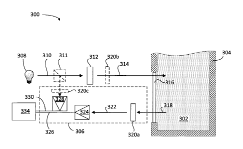
[0057] FIG. 3 illustrates an exemplary system 300 for monitoring a bulk
material or powder 302, according to one or more embodiments. In the
illustrated
embodiment, bulk material or powder 302 may be contained within a container
304. In at least one embodiment, container 304 may be a scale tank that
actively
mixes bulk material or powder 302 present therein into a cement composition
while
system 300 collects measurements. In at least one embodiment, container 304
may be a cup or the like of a transport unit, such as a truck or a boat. In
other
embodiments container 304 may be any other type of container, as generally
described or otherwise defined herein. For example, container 304 may be a
storage vessel or silo, or a pipeline such as a transfer tube used in the oil
and gas
industry, e.g., in a pneumatic conveying system.
[0058] System 300 may include at least one optical computing device 306,
which may be similar in some respects to optical computing device 200 of FIG.
2.
While not shown, device 306 may be housed within a casing or housing
configured
to substantially protect the internal components of device 306 from damage or
contamination from the external environment. The housing may couple device 306
to container 304 mechanically with mechanical fasteners, threads, brazing or
welding techniques, adhesives, magnets, combinations thereof or the like.
[0059] As described in detail below, optical computing device 306 may be
useful in determining a particular characteristic of bulk material or powder
302
within container 304, such as determining a concentration of an analyte
present
within bulk material or powder 302.
[0060] Knowing at least some of the characteristics of bulk material or
powder 302 may help determine the overall composition of the bulk material or
powder 302. Knowing the composition of bulk material or powder 302 allows for
a
more accurate determination of the composition and/or concentration of cement
slurry additives to use in subsequent cement slurries. In turn, the cementing
operation that utilized the cement slurry mitigates premature setting or
delayed
setting. Further, the resultant set cement may be of higher quality because
the
type of and concentration of additives was tailored to the original dry
cement.
[0061] In some embodiments, device 306 may include an electromagnetic
radiation source 308 configured to emit or otherwise generate electromagnetic
19
CA 3055593 2019-09-13
radiation 310. Electromagnetic radiation source 308 may be any device capable
of
emitting or generating electromagnetic radiation, as defined herein. For
example,
electromagnetic radiation source 308 may be a light bulb, a light emitting
diode
(LED), a laser, a blackbody, a photonic crystal, an X-Ray source, combinations
thereof, or the like. In some embodiments, a lens 312 collects or otherwise
receives electromagnetic radiation 310 and directs a beam 314 of
electromagnetic
radiation 310 toward bulk material or powder 302. Lens 312 may be any type of
optical device configured to transmit or otherwise convey electromagnetic
radiation
310 as desired. For example, lens 312 may be a normal lens, a Fresnel lens, a
diffractive optical element, a holographic graphical element, a mirror (e.g.,
a
focusing mirror), a type of collimator, or any other electromagnetic radiation-
transmitting device known to those skilled in the art. Some embodiments omit
lens
312 from device 306 and electromagnetic radiation source 308 conveys
electromagnetic radiation 310 toward bulk material or powder 302 directly from
the
electromagnetic radiation source 308. In some embodiments, lens 312 includes a
plurality of optical elements such as lenses and mirrors configured to direct
light
from electromagnetic radiation source 308 into bulk material or powder 302.
[0062] In one or more embodiments, device 306 may also include a
sampling window 316 arranged adjacent to or otherwise in contact with bulk
material or powder 302 for detection purposes. In some embodiments, sampling
window 316 includes any one of a variety of transparent, rigid or semi-rigid
materials that allow transmission of electromagnetic radiation 310
therethrough.
For example, sampling window 316 may include materials such as, but not
limited
to, glasses, plastics, semi-conductors, crystalline materials, sapphire,
polycrystalline materials, hot or cold-pressed powders, combinations thereof,
or the
like.
[0063] After passing through sampling window 316, electromagnetic
radiation 310 impinges upon and optically interacts with bulk material or
powder
302, including any analytes present within bulk material or powder 302. As a
result, bulk material 302 generates and reflects optically interacted
radiation 318.
Those skilled in the art, however, will readily recognize that alternative
variations of
device 306 allow optically interacted radiation 318 to be transmitted,
scattered,
CA 3055593 2019-09-13
diffracted, absorbed, emitted, or re-radiated by and/or from the bulk material
or
powder 302, or one or more analytes present within the bulk material or powder
302, without departing from the scope of the disclosure.
[0064] ICEs 320a, 320b and 320c (hereinafter collectively referred to as
ICEs 320) may be included in device 306. ICE 320a directs or otherwise
receives
optically interacted radiation 318, generated by the interaction with bulk
material or
powder 302. ICE devices 320 may include spectral components substantially
similar to ICE 100 described above with reference to FIG. 1. Accordingly, in
operation ICE 320a receives the optically interacted radiation 318 and
produces
modified electromagnetic radiation 322 corresponding to a particular
characteristic
of interest of the bulk material or powder 302.
In particular, the modified
electromagnetic radiation 322 is electromagnetic radiation that has optically
interacted with ICE 320a and obtains an approximate mimicking of the
regression
vector corresponding to the characteristic of interest. In some embodiments,
the
characteristic of interest corresponds to bulk material or powder 302. In
other
embodiments, the characteristic of interest corresponds to a particular
analyte
found in the bulk material or powder 302. In some embodiments, the
characteristic
of interest may be air contained in a flow of bulk material or powder 302.
[0065] It should be noted that, while FIG. 3 depicts ICE 320a as receiving
optically interacted radiation 318 from bulk material or powder 302, an ICE
component may be arranged at any point along the optical train of the device
306,
without departing from the scope of the disclosure. For example, in one or
more
embodiments, ICE 320b (as shown in dashed lines) may alternatively be arranged
within the optical train prior to the sampling window 316 and equally obtain
substantially the same results. In other embodiments, sampling window 316 may
serve a dual purpose as both a transmission window and a substrate for one of
ICEs
320 (i.e., a spectral component). In yet other embodiments, the ICE components
320 may generate modified electromagnetic radiation 322 through reflection,
instead of transmission thereth rough.
[0066] Moreover, while only one ICE 320a is shown in device 306,
embodiments are contemplated herein which include the use of at least two ICEs
320 in device 306 configured to cooperatively determine the characteristic of
21
CA 3055593 2019-09-13
interest in bulk material or powder 302. For example, two or more ICE 320
arranged in series or parallel within device 306 receive optically interacted
radiation
318 thereby enhancing sensitivities and detector limits of device 306. In some
embodiments, two or more ICEs 320 may be arranged on a movable assembly,
such as a rotating disc or an oscillating linear array, which moves such that
individual ICEs 320 are able to be exposed to or otherwise optically interact
with
electromagnetic radiation 310 for a distinct brief period. The two or more
ICEs 320
in any of these embodiments may be associated or disassociated with the
characteristic of interest in bulk material or powder 302. In other
embodiments,
the two or more ICEs 320 may have a positive or a negative correlation with
the
characteristic of interest. Further, according to some embodiments, two ICEs
320
have opposite correlation with the characteristic of interest. In such
embodiments,
while a signal in detector 324 increases with an increase in the
characteristic of
interest for a first ICE 320, the signal in detector 324 decreases for a
second ICE
320.
[0067] In some embodiments, it may be desirable to monitor more than
one characteristic of interest at a time using device 306. In such
embodiments,
various configurations for multiple ICEs 320 can be used, where each ICE 320
is
configured to detect a particular and/or distinct characteristic of interest
corresponding, for example, to bulk material or powder 302 or to an analyte in
the
bulk material or powder 302. Some embodiments analyze the characteristic of
interest sequentially using multiple ICEs 320 interacting with a single beam
of
optically interacted radiation 318 reflected from or transmitted through bulk
material or powder 302. For example, some embodiments include multiple ICEs
320 arranged on a rotating disc. In such embodiments, the beam of optically
interacted radiation 318 interacts with individual ICEs 320 for a reduced
time.
Advantages of this approach can include the ability to analyze multiple
characteristics of interest within bulk material or powder 302 using device
306 and
the opportunity to assay additional characteristics simply by adding
additional ICEs
320 to the rotating disc corresponding to those additional characteristics.
[0068] Other embodiments place multiple devices 306 at a single location
along container 304, where each device 306 contains a unique ICE 320 that is
22
CA 3055593 2019-09-13
configured to detect a particular characteristic of interest. In such
embodiments, a
beam splitter can divert a portion of the optically interacted radiation 318
reflected
by, emitted from, or transmitted through the bulk material or powder 302 and
into
each one of devices 306. Each one of devices 306, in turn, may couple to a
corresponding detector (e.g., detector 324) or detector array configured to
detect
and analyze an output of electromagnetic radiation from the respective optical
computing device. Parallel configurations of optical computing devices can be
particularly beneficial for applications that require low power inputs and/or
no
moving parts.
[0069] Those skilled in the art will appreciate that any of the foregoing
configurations can include a series configuration in any of the present
embodiments. For example, a movable housing may arrange two devices 306 in
series to perform an analysis at a single location in container 304. Likewise,
multiple detection stations, each containing devices 306 in parallel, can
perform a
similar analysis in series.
[0070] Modified electromagnetic radiation 322 generated by ICE 320a may
subsequently be conveyed to the detector 324 for quantification of the signal.
Detector 324 may be any device capable of detecting electromagnetic radiation,
such as an optical transducer. In some embodiments detector 324 is a thermal
detector such as a thermopile or photo-acoustic detector, a semiconductor
detector,
a piezo-electric detector, a charge coupled device (CCD) detector, a video or
array
detector, a split detector, a photon detector (such as a photomultiplier
tube),
photodiodes, combinations thereof, or the like, or other detectors known to
those
skilled in the art.
[0071] In some embodiments, detector 324 may be configured to produce
an output signal 326 in real-time or near real-time in the form of a voltage
(or
current) that corresponds to the particular characteristic of interest in bulk
material
or powder 302. The voltage returned by detector 324 is essentially the dot
product
of the optical interaction of optically interacted radiation 318 with ICE 320a
as a
function of the concentration of the characteristic of interest. As such,
output
signal 326 produced by detector 324 is related to the characteristic of
interest. For
example, output signal 326 may be directly proportional to the characteristic
of
23
CA 3055593 2019-09-13
interest. In other embodiments, however, the relationship may correspond to a
polynomial function, an exponential function, a logarithmic function, and/or a
combination thereof. In some embodiments, output signal 326 associated with
ICE
320a may be negatively correlated with the characteristic of interest.
Accordingly,
output signal 326 decreases when the characteristic of interest increases.
[0072] In some embodiments, device 306 may include a second detector
328, which may be similar to first detector 324 in that it may be any device
capable
of detecting electromagnetic radiation. Similar to second detector 216 of FIG.
2,
second detector 328 of FIG. 3 detects radiating deviations stemming from the
electromagnetic radiation source 308. Accordingly, a beam splitter 311 (in
dashes)
may direct a portion of electromagnetic radiation 310 to detector 328, which
may
be configured to monitor radiating deviations in electromagnetic radiation
source
308. In some embodiments, another ICE device 320c (shown in dashes) before
detector 328 modifies the electromagnetic radiation impinging on detector 328.
Undesirable radiating deviations can occur in the intensity of the
electromagnetic
radiation 310 due to a wide variety of reasons and potentially causing various
negative effects on the output of the device 306. These negative effects can
be
particularly detrimental for measurements taken over a period.
In some
embodiments, radiating deviations can occur due to a build-up of a layer of
residual
material on sampling window 316. This reduces the amount and quality of light
ultimately reaching first detector 324.
Without proper compensation, such
radiating deviations could result in false readings and output signal 326 may
inaccurately relate the characteristic of interest.
[0073] To compensate for these undesirable effects, second detector 328
generates a compensating signal 330 generally indicative of the radiating
deviations
of the electromagnetic radiation source 308, thereby normalizing output signal
326
generated by first detector 324. As illustrated, second detector 328 may
receive a
portion of optically interacted radiation 318 via a beam splitter 332 in order
to
detect the radiating deviations. In some embodiments, second detector 328
receives electromagnetic radiation from any portion of the optical train in
device
306 to detect radiating deviations, without departing from the scope of the
disclosure.
24
CA 3055593 2019-09-13
[0074] In some applications, output signal 326 and compensating signal
330 may be conveyed to or otherwise received by a signal processor 334
communicably coupled to both detectors 324, 328. Signal processor 334 may be a
computer including a non-transitory machine-readable medium, configured to
normalize output signal 326 using compensating signal 330, in view of any
radiating deviations detected by second detector 328. In some embodiments,
computing output and compensating signals 326, 330 may entail computing a
ratio
of the two signals 326, 330. For example, the concentration or magnitude of
each
characteristic of interest determined using optical computing device 306 are
input
to an algorithm run by signal processor 334. The algorithm predicts how the
bulk
material or powder 302 in combination with cement slurry additives, optionally
at
varying concentrations, will behave in cement slurries.
[0075] Systems similar to that illustrated in FIG. 3 may be useful in
analyzing bulk material or powders. For example, a system may include a probe
inserted into dry cements for analysis of a characteristic thereof. As such,
the dry
cement may be contained within a container not having a device 306 connected
thereto (e.g., a bag of dry cement as shipped from a distributor). Further,
the dry
cement may be a pile or mound of dry cement in open air.
[0076] Those skilled in the art will readily recognize that, in one or more
embodiments, electromagnetic radiation derives from the bulk material or
powder
302. For example, various substances naturally radiate electromagnetic
radiation
that is able to interact with at least one of ICE components 320. In some
embodiments, for example, bulk material or powder 302 or a substance within
the
bulk material or powder 302 may be a blackbody radiating substance configured
to
radiate heat that may optically interact with at least one of ICE components
320.
In other embodiments, the bulk material or powder 302 or the substance within
the
bulk material or powder 302 may be radioactive or chemo-luminescent and emit
electromagnetic radiation that is able to interact with ICE 320. In yet other
embodiments, mechanical, magnetic, electric, actuation induces electromagnetic
radiation from bulk material or powder 302 or from a substance within the bulk
material or powder 302. For instance, in at least one embodiment, a voltage
across
bulk material or powder 302 or the substance within bulk material or powder
302
CA 3055593 2019-09-13
induces the electromagnetic radiation. As a result, in embodiments
contemplated
herein the electromagnetic radiation source 308 may be omitted from the
particular
optical computing device.
[0077] FIG. 4 illustrates an exemplary housing 400 used to house an
optical computing device, according to one or more embodiments. In some
embodiments, housing 400 couples mechanically to container 304 using, for
example, mechanical fasteners, brazing or welding techniques, adhesives,
magnets,
combinations thereof or the like. Housing 400 substantially protects the
internal
components of device 306 from damage or contamination from the external
environment. Those skilled in the art, however, will readily recognize that
several
alternative designs and configurations of housings used to house the optical
computing devices are suitable for the presently disclosed systems and
methods.
Indeed, housing embodiments described and disclosed herein are by way of
example only, and should not limit the scope to the exemplary systems and
methods disclosed herein.
[0078] As illustrated, the housing 400 may be in the general form of a bolt
450, which encloses the various components of an optical computing device,
such
as device 306 of FIG. 3. In one embodiment, components of the device 306
housed within housing 400 may be generally housed within a stem 452 of a bolt
450, and bolt 450 may have a hex head 454 for manual manipulation of housing
400 using, for example, a wrench or other suitable torque-generating hand
tool.
[0079] In at least one embodiment, housing 400 defines external threads
456 that are compatible with corresponding mating pipe threads provided in,
for
example, an opening defined in container 304 (FIG. 3) that is configured to
receive
housing 400. A thread sealant between threads 456 and the mating pipe threads
may prevent leakage of moisture or any undesirable substance through the
juncture between housing 400 and the pipe. Sampling window 316 is configured
to
be in optical communication with bulk material or powder 302 (FIG. 3) and
allows
optical interaction between bulk material or powder 302 and other internal
components of internally housed device 306.
[0080] FIG. 5 illustrates a system 500 for storing and conveying raw
materials from storage containers 505 to transport units 550 including an
optical
26
CA 3055593 2019-09-13
computing device 506, according to some embodiments. System 500 includes a
storage container 505 including at least one of a hopper 502 or a storage bin
504 to
store a bulk material or powder 501. Hopper 502 may be a storage container
with
an open top, while storage bin 504 may include a top enclosure (e.g., a tank).
Bulk
material or powder 501 may include any one of fly ash, silica flour, salts, or
any of
the materials mentioned above in a dry cement combination, including cement
additives in powder form. Other dry materials 501 besides dry cement that may
be
transferred in hopper 502 include salt, lime, sand, POZMIX , and the like. In
some
embodiments of system 500, hopper 502 conveys different materials through
transfer tube 507a into scale tank 510, sequentially. Transfer tube 507a
conveys
bulk material or powder 501 from any one of storage containers 505 (including
storage bin 504) to a scale tank 510. In some embodiments, a pump 530 creates
a
negative air pressure in the scale tank to generate a flow of bulk material or
powder 501, thus 'pulling' bulk material or powder 501 through transfer tube
507a.
In other embodiments, the bulk material may gravity flow from 505 through 507a
into 510. Scale tank 510 receives raw materials from different storage
containers
505 such as hopper 502 and storage bin 504 and forms a mix, such as dry
cement.
The mixture may be developed by ribbon blending, jets, multiple transfers and
such, with 506d determining when the mixture is satisfactorily homogeneous.
Transfer tube 507b conveys the mixed materials to a truck 550a or a ship 550b
for
shipping the blended materials (e.g., dry cement) to a deployment location.
Transfer tubes 507a and 507b will be referred hereinafter to as transfer tubes
507.
In some embodiments transfer tube 507b includes a flow of the bulk material or
powder mixed with air, the air provided by an air pump 540 creating a positive
air
pressure in the scale tank, thus 'pushing' bulk material or powder 501 through
transfer tube 507b. In some embodiments, the role of pump 530 and air
compressor 540 may be reversed, so that an air compressor 540 'pushes' raw
material from storage containers 505 into scale tank 510. Or in some
embodiments
pump 530 may be used to 'pull' a material mix from scale tank 510 to transport
units 550a (e.g., a truck) and 550b (e.g., a ship). Transport units 550a and
550b
will be referred hereinafter to as transport units 550.
27
CA 3055593 2019-09-13
[0081] In some embodiments, it may be desirable to know in real time
that the correct material is in any one of storage containers 505, or in any
one of
transfer tubes 507, scale tank 510, or even within transport units 550.
Accordingly,
system 500 includes a plurality of optical computing devices disposed in
different
locations. Optical computing device 506a is located within hopper 502. Optical
computing device 506b is located within storage bin 504.
Optical computing
device 506c is located within transfer tube 507a. Optical computing device
506d is
located within scale tank 510. Optical computing device 506e is located within
transfer tube 507b. Optical computing device 506f is located within truck
550a,
and optical computing device 506g is located within ship 550b. Optical
computing
devices 506a-g will be collectively referred to hereinafter as optical
computing
devices 506. In some embodiments, at least one of optical computing devices
506
may be as optical computing device 306 in FIG. 3.
[0082] System 500 also includes a signal processor 534 having a processor
circuit 536 and a memory circuit 537 storing commands. Signal processor 534
may
be similar to signal processor 334 of FIG. 3. When executed by processor
circuit
536 the commands cause signal processor 534 to perform a method including
receiving a first signal from a first optical computing device 506a at a first
location
in system 500. The commands may also cause signal processor 534 to perform the
step of receiving a second signal from a second optical computing device 506b
at a
second location in system 500. The first and second location in system 500 may
be
any one of storage containers 505, transfer tubes 507, scale tank 510, or even
transport units 550. In that regard, optical computing devices 506 and signal
processor 534 may exchange data and signals via a wire connection, or a
wireless
.. connection. The first and second signal may result from a light interacted
with a
bulk material or powder 501, and at least one of the first and second signals
results
from an electromagnetic radiation modified by an ICE. In some embodiments, the
commands further cause signal processor 534 to perform the step of determining
from the first and second signal a characteristic of the bulk material or
powder, or
of the flow of the bulk material or powder. More generally, processor circuit
536
may execute commands stored in memory circuit 537 that cause signal processor
534 to perform at least one of the steps in any method consistent with the
present
28
CA 3055593 2019-09-13
disclosure. A Human Machine Interface (HMI) 560 may be coupled to signal
processor 534, and be configured to monitor the operation of system 500 by a
human operator. Accordingly, HMI 560 may issue warnings, alert messages, or
alarms, based on the data provided by signal processor 534 upon collecting
signals
from each of optical computing devices 506.
[0083] Optical computing devices 506 enable real time monitoring and
detection of various compounds in most any phase, including powders, liquids
and
slurries. For example, an ICE in any one of optical computing devices 506
(e.g.,
ICE 100 in FIG. 1) may identify cement powder ingredients used in dry cement
compositions. Monitoring and detecting the chemical composition (or at least
key
ingredients) through optical computing devices 506 enables identification and
verification of bulk material or powder 501 in hopper 502, in storage bin 504
or in
one of the transfer tubes 507a and 507b. Optical computing devices 506 also
enable detection of the condition of bulk material or powder 501. For example,
optical computing devices 506 may determine when excessive moisture or
decomposition occurs in storage or while conveyed in and out of scale tank
510. A
window or a probe provides optical communication between optical computing
devices 506 and storage containers 505, transfer tubes 507, or transport units
550.
The window may be similar to window 316 of FIG. 3, and the probe may include a
.. waveguide device to transmit electromagnetic radiation, such as an optical
fiber.
[0084] Accordingly, methods and systems consistent with the present
disclosure provide fast identification of dry materials contained in a storage
bin, a
hopper, or a pneumatic conveyor. System 500 also includes a programmed control
system with alarms and reporting to prevent contamination of bulk materials or
powders from interconnecting piping with different storage bins, or from
different
materials delivered to the storage bin or hopper.
Accordingly, system 500
enhances the confidence level for adding to a blend the correct materials in
their
suitable condition. Accordingly, embodiments consistent with the present
disclosure decrease the likelihood of ruined bulk material or powder batches
being
.. disposed of. Thus decreasing waste disposal costs and material costs to the
plant.
Methods and systems consistent with the present disclosure also decrease the
likelihood of compromised bulk material blends: arriving on location, mixing
in a
29
CA 3055593 2019-09-13
blend, and pumped into a borehole. This also decreases the cost of poor
quality,
and the likelihood of downtime due to test and repair of damaged structures.
Furthermore, embodiments consistent with the present disclosure decrease
occurrence of equipment damage due to flash setting in the mixing and pumping
system and/or poor slurry mixability.
[0085] FIG. 6 illustrates a storage bin 504 including optical computing
devices 506h, 506i, and 506j (hereinafter collectively referred to as optical
computing devices 506), to identify material type and condition of a bulk
material
or powder 501, according to some embodiments. Optical computing devices 506h-j
may be similar in some respects (or the same as) any of the optical computing
devices described herein (cf. FIG. 5). The optical analysis systems 506h-j may
be
operatively coupled to a sidewall of the storage bin 504 at separate locations
and in
optical communication with the bulk material or powder 501 contained therein.
And
optical computing device 506k may be embedded in the interior of storage bin
504,
surrounded by bulk material or powder 501. While storage bin 504 is depicted
in
FIG. 6 as being vertically positioned, it is further contemplated herein to
have a
storage bin 504 that is horizontally situated, where a width or diameter of
the
storage bin 504 is greater than a height, without departing from the scope of
the
disclosure.
[0086] A signal processor 634 may be communicably coupled to each of
optical computing devices 506 and is configured to collect a signal from each
optical
computing device 506 and determine a value of a characteristic of material or
powder 501. In some embodiments, a first optical computing device 506h may be
arranged on an upper portion of the storage bin 504 such that it is able to
interact
optically with a first type or condition 601 of bulk material or powder 501
disposed
at or near the upper portion of the storage bin 504. A second optical
computing
device 506i may be arranged at an intermediate portion or location of the
storage
bin 504 such that it is able to interact optically with a second type or
condition 602
of bulk material or powder 501 disposed at or near the intermediate location
of the
storage bin 504. A third optical computing device 506j may be arranged at or
near
a bottom upper portion of the storage bin 504 such that it is able to interact
optically with a third type or condition 603 of bulk material or powder 501
disposed
CA 3055593 2019-09-13
at or near the bottom portion of the storage bin 504. And a fourth optical
computing device 506k may be surrounded by bulk material or powder 501 in
either one of conditions 601, 602, and 603. Accordingly, a plurality of
optical
computing devices 506 may be embedded in different locations within storage
bin
504. In that regard, a signal generated by a radio-frequency (RF) transmitter
in
optical computing device 506k may indicate the precise location of the device
within
storage bin 504 to signal processor 634, in addition to providing a signal
regarding
an optical characteristic of the surrounding bulk material or powder 501.
Optical
computing device 506k may include self-contained, wireless transceivers, and
its
own battery powered optical source. Accordingly, optical computing device 506k
may have a spherical form factor, and be placed randomly in different sections
of
storage bin 504 to occasionally broadcast information of interest to a
wireless
receiver in signal processor 634. Further, according to some embodiments,
optical
computing device 506k may be coupled to receive an optical source from outside
storage bin 504, through an optical fiber. In some embodiments, signal
processor
634 provides separate "signatures" for each type or condition 601, 602, and
603 of
bulk material or powder 501, and compares them with known or desirable
"signatures" for the bulk material or powder 501. Accordingly, signal
processor 634
may trigger an alarm or report the data from optical computing devices 506
and/or
any discrepancies to a central unit, or to authorized maintenance personnel so
that
one or more remedial actions may be undertaken.
[0087] While FIG. 6 illustrates material types or conditions 601, 602, and
603 arranged substantially vertically along storage bin 504, the number of
material
types or conditions and their arrangement within storage bin 504 is not
limiting of
the scope of the present disclosure. More specifically, material type 601 may
include fines and a more dry type of material than material types 602 and 603.
Material type 602 may include average particle size, as determined by data
stored
in a database in signal processor 634. Material type 603 may include coarser
particle sizes and a higher moisture concentration in the bulk material or
powder
501, such as saturated materials. In that regard, the difference between
material
types 601, 602, and 603 may result from gravity and/or humidity, as bigger,
31
CA 3055593 2019-09-13
heavier particles tend to percolate or descend to the bottom portions of
storage bin
504.
[0088] Storage bin 504 may be any type of storage container or vessel
configured to contain and otherwise store dry materials, such as bulk material
or
powder 501, which may comprise a dry cement composition. The storage bin 504
may include a portable or stationary storage bin, a horizontal or vertical
storage
bin, of bolted or welded construction. Moreover, storage bin 504 may comprise
a
pressurized or non-pressurized storage bin. In some embodiments, optical
analysis
systems 400 send real time data to a computing system in signal processor 634.
In
some embodiments, optical computing devices 506 avoid the occurrence of error
and mishandling of the components of a dry cement prior to mixing. For
example,
optical computing device 506 may be able to determine that the material in
storage
bin 504 has been improperly labeled or misplaced, thus sending an alert signal
through signal processor 634 to an HMI (e.g., HMI 560, cf. FIG. 5).
[0089] FIG. 7 illustrates a flowchart including steps in a method 700 for
identification of material type and condition in a bulk material or powder
storage
bin, according to some embodiments. Embodiments consistent with method 700
include a storage bin in a system for storing and conveying materials from
storage
containers to transport units (e.g., storage containers 505, storage bin 504,
and
system 500, cf. FIGS. 5 and 6). Accordingly, a material storage bin in methods
consistent with method 700 may include at least one optical analysis system
that
has an ICE, a detector, and a signal processor (e.g., detectors 324 and 328,
and
signal processor 334, cf. FIG. 3, and optical computing device 506 cf. FIG.
5). In
some embodiments, a plurality of optical analysis systems (e.g., optical
computing
devices 506h-j of FIG. 6) is mounted on a storage bin (e.g., storage bin 504
of FIG.
6) to determine a characteristic of a bulk material or powder (e.g., bulk
material or
powder 501 of FIG. 6) contained within the storage bin. Furthermore, in some
embodiments the optical computing device may be embedded within the bulk
material or powder in the interior of the storage bin (e.g., optical computing
device
506k of FIG. 6). In some instances, at least one of the steps in method 700
includes using computers and optionally artificial neural networks. For
example, in
some embodiments at least one or more of the steps in method 700 include a
32
CA 3055593 2019-09-13
signal processor circuit executing commands stored in a memory circuit, and
coupled to an HMI (e.g., signal processor 534, processing circuit 536, memory
circuit 537, and HMI 560, cf. FIG. 5). Steps in methods consistent with the
present
disclosure may include at least any of the steps in method 700, performed in
any
order. Furthermore, embodiments consistent with the present disclosure may
include one or more of the steps in method 700 performed overlapping in time,
or
simultaneous in time.
[0090] Step 710 includes optically interacting a bulk material or powder at
a selected point in a storage bin with an ICE. Accordingly, the ICE may be
configured to obtain a modified electromagnetic radiation from the interacted
electromagnetic radiation. The modified electromagnetic radiation may be
correlated to a characteristic of the bulk material or powder.
In some
embodiments, step 710 includes providing an electromagnetic radiation to be
interacted with the bulk material or powder at a selected point in the storage
bin.
In some embodiments, step 710 includes providing an electromagnetic radiation
source, and in some embodiments step 710 may include using an electromagnetic
radiation generated internally in the storage bin (e.g., by a flare sparked
inside the
storage bin). Further, in some embodiments step 710 includes using a natural
electromagnetic radiation source from the sun or any other natural source.
Step
720 includes detecting the modified electromagnetic radiation resulting from
interacting the bulk material or powder with the ICE, using a detector. Step
720
includes receiving the modified electromagnetic radiation in the detector.
[0091] Step 730 includes producing an output signal correlated with the
characteristic of the bulk material or powder at the selected point in the
storage
bin. Step 730 includes determining a value of a characteristic of the stored
bulk
material or powder using the signal processor. The characteristic of the bulk
material or powder may be a chemical composition of the bulk material or
powder,
a purity value (e.g., 98%, 99% concentration or higher), a contaminant
concentration value, a moisture concentration value, a particle size value, a
homogeneity, and an air content, among others. In
some embodiments,
determining particle size of the bulk material or powder may prove useful in
determining a quality or a type of the bulk material or powder stored in the
storage
33
CA 3055593 2019-09-13
bin. For example, larger particle sizes may lead to a reduced strength set
cement,
and may therefore require or otherwise benefit from a strengthening cement
slurry
additive (e.g., fibers or other resilient particles). Conversely, bulk
materials or
powders with smaller particle sizes typically use more water to hydrate
completely
because of the increased surface area relative to weight. In some embodiments,
step 730 further includes associating a location in the storage bin with the
value of
the characteristic of the bulk material or powder.
[0092] Step 740 includes determining whether the bulk material or powder
is suitable for continued storage.
In some embodiments step 740 includes
comparing the value of the characteristic of the stored bulk material or
powder to a
database including ranges of acceptable values. When the bulk material or
powder
is suitable for continued storage, steps 710 through 740 may be repeated as
described above. Further, in some embodiments step 740 includes transmitting a
validation message when it is determined that the bulk material or powder is
suitable for continued storage. Step 750 includes transmitting an alert when
the
bulk material or powder is not suitable for continued storage.
In some
embodiments step 750 includes alerting an administrator and transmitting a
message flagging the storage bin. Accordingly, step 750 may include triggering
an
alarm so that authorized personnel take appropriate action by removing the
bulk
material or powder from the storage bin, or correcting the configuration of
the
storage and conveyance system.
[0093] When the system detects a discrepancy in the material contained
storage tank versus the criteria stored in the system, some embodiments close
and
lock a transfer tube from the storage containers to the scale tank. For
example, in
some embodiments a valve in the transfer tube between the storage containers
and
the scale tank is closed. Some embodiments issue a warning (pop-up) on the
screen of the HMI, stating what the discrepancy is, that the operator must
acknowledge before continued operation of the material transfer from the
storage
tank to the scale tank is allowed. It should also record this event and the
operator's response to the warning in the system for later reporting.
[0094] The various embodiments herein directed to computer control and
artificial neural networks, including various blocks, modules, elements,
34
CA 3055593 2019-09-13
components, methods, and algorithms, can be implemented using computer
hardware, software, combinations thereof, and the like. To illustrate this
interchangeability of hardware and software, various illustrative blocks,
modules,
elements, components, methods and algorithms have been described generally in
terms of their functionality. Whether such functionality is implemented as
hardware or software will depend upon the particular application and any
imposed
design constraints. For at least this reason, it is to be recognized that one
of
ordinary skill in the art can implement the described functionality in a
variety of
ways for a particular application. Further, various components and blocks can
be
arranged in a different order or partitioned differently, for example, without
departing from the scope of the embodiments expressly described.
[0095] Computer hardware used to implement the various illustrative
blocks, modules, elements, components, methods, and algorithms described
herein
can include a processor configured to execute one or more sequences of
instructions, programming stances, or code stored on a non-transitory,
computer-
readable medium.
The processor can be, for example, a general purpose
microprocessor, a microcontroller, a digital signal processor, an application
specific
integrated circuit, a field programmable gate array, a programmable logic
device, a
controller, a state machine, a gated logic, discrete hardware components, an
artificial neural network, or any like suitable entity that can perform
calculations or
other manipulations of data. In some embodiments, computer hardware can
further include elements such as, for example, a memory (e.g., random access
memory (RAM), flash memory, read only memory (ROM), programmable read only
memory (PROM), erasable read only memory (EPROM)), registers, hard disks,
removable disks, CD-ROMs, DVDs, or any other like suitable storage device or
medium.
[0096] Executable sequences described herein can be implemented with
one or more sequences of code contained in a memory. In some embodiments,
such code can be read into the memory from another machine-readable medium.
Execution of the sequences of instructions contained in the memory can cause a
processor to perform the process steps described herein. One or more
processors
in a multi-processing arrangement can also be employed to execute instruction
CA 3055593 2019-09-13
sequences in the memory. In addition, hard-wired circuitry can be used in
place of
or in combination with software instructions to implement various embodiments
described herein. Thus, the present embodiments are not limited to any
specific
combination of hardware and/or software.
[0097] As used herein, a machine-readable medium will refer to any
medium that directly or indirectly provides instructions to a processor for
execution.
A machine-readable medium can take on many forms including, for example, non-
volatile media, volatile media, and transmission media. Non-volatile media can
include, for example, optical and magnetic disks. Volatile media can include,
for
example, dynamic memory. Transmission media can include, for example, coaxial
cables, wire, fiber optics, and wires that form a bus. Common forms of machine-
readable media can include, for example, floppy disks, flexible disks, hard
disks,
magnetic tapes, other like magnetic media, CD-ROMs, DVDs, other like optical
media, punch cards, paper tapes and like physical media with patterned holes,
RAM, ROM, PROM, EPROM, and flash EPROM.
[0098] Embodiments disclosed herein include:
[0099] A. A method that includes optically interacting a bulk material or
powder stored in a storage bin with an integrated computational element
("ICE")
configured to modify an electromagnetic radiation according to a
characteristic of
the bulk material or powder, detecting the modified electromagnetic radiation
with
a detector, producing an output signal with a signal processor, the output
signal
being correlated to the characteristic of the bulk material or powder,
determining
whether the bulk material or powder is suitable for continued storage in the
storage
bin, and transmitting an alert when it is determined that the bulk material or
powder is not suitable for continued storage or usage, wherein the bulk
material or
powder comprises at least one of a dry cement or a dry cement component.
[00100] B. A device that includes a processor circuit, and a memory circuit
storing commands, which when executed by the processor circuit cause the
device
to perform a method comprising receiving a first signal from a first optical
computing device at a first location in a system for storing and conveying
materials, receiving a second signal from a second optical computing device at
a
second location in the system for storing and conveying materials, wherein at
least
36
CA 3055593 2019-09-13
one of the first and second signal result from an electromagnetic radiation
interacted with a dry cement component stored in a storage bin, and at least
one of
the first and second signals results from an electromagnetic radiation
modified by
an Integrated Computational Element (ICE) according to a characteristic of the
dry
cement, determining a characteristic of the dry cement component, determining,
based on the characteristic of the dry cement component, whether the dry
cement
component is suitable for continued storage, and transmitting a message
flagging
the storage bin when it is determined that the dry cement component is not
suitable for continued storage.
[00101] C. A method that includes receiving an output signal from each of
a plurality of optical computing devices disposed in separate locations in a
storage
bin comprising a stored bulk material or powder, processing each of the output
signals from the plurality of optical computing devices with a signal
processor,
determining a characteristic of the stored bulk material or powder based on
the
processing of the output signals, and transmitting an alert when it is
determined
that the bulk material or powder is not suitable for continued storage.
[00102] Each of embodiments A, B, and C may have one or more of the
following additional elements in any combination:
Element 1: wherein the
characteristic of the bulk material or powder is at least one of a moisture
content or
a contaminant. Element 2: wherein producing an output signal being correlated
to
the characteristic of the bulk material or powder comprises determining a
concentration of fines. Element 3: further comprising associating a location
in the
storage bin with the characteristic of the bulk material or powder. Element 4:
further comprising triggering an alarm when it is determined that the bulk
material
or powder is not suitable for continued storage. Element 5: further comprising
transmitting a message clearing the storage bin when it is determined that the
bulk
material or powder is suitable for continued storage.
Element 6: wherein
determining whether the bulk material or powder is suitable for continued
storage
comprises comparing, in a database, a value obtained from the characteristic
of the
sample with a range of acceptable values. Element 7: further wherein
transmitting
an alert comprises closing a valve in a transfer tube coupling the storage bin
with a
scale tank in a system for storing and conveying raw materials. Element 8:
37
CA 3055593 2019-09-13
wherein transmitting an alert when it is determined that the bulk material or
powder is not suitable for continued storage or usage comprises alerting that
the
bulk material or powder has been wrongly labeled or misplaced.
[00103] Element 9: wherein the memory circuit further comprises a
database having a range of acceptable values for the characteristic of the dry
cement component, and the commands further cause the device to perform the
step of comparing the value of the characteristic of the dry cement
composition
with the database. Element 10: wherein the characteristic of the dry cement
component comprises a composition of fines of the dry cement component.
Element 11: wherein the characteristic of the dry cement component comprises a
humidity value and a contamination material content. Element 12: wherein the
memory circuit further comprises commands that cause the device to perform the
step of associating a location in the storage bin with the characteristic of
the dry
cement component. Element 13: wherein the memory circuit further comprises
commands that cause the device to perform the steps of associating a first
location
of the first optical computing device with a first characteristic of the dry
cement
component obtained from the first optical computing device, and associating a
second location of the second optical computing device with a second value of
the
characteristic of the dry cement component obtained from the second optical
computing device. Element 14: wherein the memory circuit further comprises
commands that cause the device to perform the step of triggering an alarm when
it
is determined that the dry cement component is not suitable for continued
storage.
Element 15: further comprising a wireless communication circuit configured to
communicate with at least one of the first optical computing device and the
second
optical computing device. Element 16: wherein at least one of the first
optical
computing device and the second optical computing device comprises a wireless
device embedded in the dry cement composition. Element 17: wherein
transmitting
a message flagging the storage bin comprises closing a valve in a transfer
tube
coupling the storage bin with a scale tank in the system for storing and
conveying
materials.
[00104] Element 18: wherein determining a characteristic of the stored bulk
material or powder comprises determining a concentration of fines in the
stored
38
CA 3055593 2019-09-13
bulk material or powder. Element 19: wherein determining a characteristic of
the
stored bulk material or powder comprises determining at least one of a
humidity
value and a contamination material content. Element 20: comprising associating
a
location in the storage bin with the characteristic of the bulk material or
powder for
each of the plurality of optical computing devices. Element 21: further
comprising
transmitting a validation message when it is determined that the bulk material
or
powder is suitable for continued storage. Element 22: further wherein
transmitting
an alert comprises closing a valve in a transfer tube coupling the storage bin
with a
scale tank in a system for storing and conveying raw materials.
[00105] The exemplary embodiments described herein are well adapted to
attain the ends and advantages mentioned as well as those that are inherent
therein. The particular embodiments disclosed above are illustrative only, as
the
exemplary embodiments described herein may be modified and practiced in
different but equivalent manners apparent to those skilled in the art having
the
benefit of the teachings herein. Furthermore, no limitations are intended to
the
details of construction or design herein shown, other than as described in the
claims below. It is therefore evident that the particular illustrative
embodiments
disclosed above may be altered, combined, or modified and all such variations
are
considered within the scope and spirit of the present invention. The invention
illustratively disclosed herein suitably may be practiced in the absence of
any
element that is not specifically disclosed herein and/or any optional element
disclosed herein. While compositions and methods are described in terms of
"comprising," "containing," or "including" various components or steps, the
compositions and methods can also "consist essentially of" or "consist of" the
various components and steps. All numbers and ranges disclosed above may vary
by some amount. Whenever a numerical range with a lower limit and an upper
limit is disclosed, any number and any included range falling within the range
is
specifically disclosed. In particular, every range of values (of the form,
"from about
a to about b," or, equivalently, "from approximately a to b," or,
equivalently, "from
approximately a-b") disclosed herein is to be understood to set forth every
number
and range encompassed within the broader range of values. Also, the terms in
the
claims have their plain, ordinary meaning unless otherwise explicitly and
clearly
39
CA 3055593 2019-09-13
defined by the patentee. Moreover, the indefinite articles "a" or "an," as
used in
the claims, are defined herein to mean one or more than one of the element
that it
introduces. If there is any conflict in the usages of a word or term in this
specification and one or more patent or other documents that may be herein
referred to, the definitions that are consistent with this specification
should be
adopted.
[00106] As used herein, the phrase "at least one of" preceding a series of
items, with the terms "and" or "or" to separate any of the items, modifies the
list as
a whole, rather than each member of the list (i.e., each item). The phrase "at
least
one of" does not require selection of at least one item; rather, the phrase
allows a
meaning that includes at least one of any one of the items, and/or at least
one of
any combination of the items, and/or at least one of each of the items. By way
of
example, the phrases "at least one of A, B, and C" or "at least one of A, B,
or C"
each refer to only A, only B, or only C; any combination of A, B, and C;
and/or at
least one of each of A, B, and C.
Date Recue/Date Received 2021-02-12