Note: Descriptions are shown in the official language in which they were submitted.
CA 03055664 2019-09-06
WO 2018/162613 PCT/EP2018/055698
NEGATIVE PRESSURE WOUND THERAPY DEVICE CONTROL IN PRESENCE
OF FAULT CONDITION
CROSS-REFERENCE TO RELATED APPLICATIONS
[0001] This application claims the benefit of U.S. Provisional
Application
No. 62/468,796, filed March 8, 2017; the disclosure of which is hereby
incorporated
by reference in its entirety.
BACKGROUND
[0002] Embodiments of the present disclosure relate to methods and
apparatuses for dressing and treating a wound with negative or reduced
pressure
therapy or topical negative pressure (TNP) therapy. In particular, but without
limitation, embodiments disclosed herein relate to negative pressure therapy
devices, methods for controlling the operation of TNP systems, and methods of
using TNP systems.
SUMMARY
[0003] In some embodiments, an apparatus for applying negative
pressure to a wound is disclosed. The apparatus can include: a wound dressing
configured to be placed over a wound of a patient; a negative pressure source
disposed on or within the wound dressing, the negative pressure source
configured
to provide negative pressure to the wound dressing via a fluid flow path; a
switch
disposed on or within the wound dressing, the switch being configured to
receive a
first user input; an interface element disposed on or within the wound
dressing, the
interface element being configured to receive a second user input; and control
circuitry. The control circuitry can be electrically coupled to the switch and
the
interface element. When in a first mode, the control circuitry can: supply of
negative
pressure with the negative pressure source in response to receipt of the first
user
input while the negative pressure source is not supplying negative pressure,
prevent supply of negative pressure with the negative pressure source in
response
-1-
CA 03055664 2019-09-06
WO 2018/162613 PCT/EP2018/055698
to receipt of the first user input while the negative pressure source is
supplying
negative pressure, and change from the first mode to a second mode different
from
the first mode in response to receipt of the second user input. When in a
second
mode, the control circuitry can disable supply of negative pressure with the
negative
pressure source.
[0004] The apparatus of the preceding paragraph can include one or more
of the following features: When the switch experiences a fault and is no
longer able
to receive the first user input, the control circuitry can prevent or disable
supply of
negative pressure with the negative pressure source in response to receipt of
no
user inputs other than the second user input. The control circuitry can supply
of
negative pressure with the negative pressure source in response to receipt of
no
user inputs other than the first user input. While the negative pressure
source is
supplying negative pressure, the control circuitry can prevent or disable
supply of
negative pressure with the negative pressure source in response to receipt of
no
user inputs other than the first user input and the second user input. When
the
control circuitry is in the second mode, the control circuitry can, in
response to
receipt of the second user input, change from the second mode to the first
mode,
and supply of negative pressure with the negative pressure source. The control
circuitry can disable supply of negative pressure with the negative pressure
source
by deactivation of operation of the negative pressure source or the control
circuitry,
opening of a vent positioned in the fluid flow path, or closing of a valve
positioned in
the fluid flow path. The control circuitry can deactivate operation of the
negative
pressure source or the control circuitry by (i) disconnection of power to the
negative
pressure source or the control circuitry or (ii) withdrawal of an enable
signal
provided to the negative pressure source or the control circuitry. The control
circuitry can prevent supply of negative pressure with the negative pressure
source
by deactivation of operation of the negative pressure source, opening of a
vent
positioned in the fluid flow path, and closing of a valve positioned in the
fluid flow
path. The interface element can be molded in film coupled to the wound
dressing.
The interface element can include an electrical contact configured to receive
the
-2-
CA 03055664 2019-09-06
WO 2018/162613 PCT/EP2018/055698
second user input. The switch can receive the first user input in response to
depression of the switch for a period of time. The period of time can be
between 0.5
seconds and 5 seconds.
[0005] A method of operating, using, or manufacturing the apparatus of
the preceding two paragraphs is also disclosed.
[0006] In some embodiments, a method of operating a negative pressure
wound therapy apparatus comprising a wound dressing is disclosed. A negative
pressure source can be disposed on or within the wound dressing, and a switch
can
be disposed on or within the wound dressing. An interface element can be
disposed on or within the wound dressing, and the switch can receive a first
user
input and the interface element can receive a second user input. The method
can
include: supplying of negative pressure with the negative pressure source to
the
wound dressing via a fluid flow path in response to receipt of the first user
input
while the negative pressure source is not supplying negative pressure to the
wound
dressing; preventing supply of negative pressure with the negative pressure
source
to the wound dressing via the fluid flow path in response to receipt of the
first user
input while the negative pressure source is supplying negative pressure to the
wound dressing; in response to receipt of the second user input, disabling
supply of
negative pressure with the negative pressure source to the wound dressing; and
subsequent to said disabling supply of negative pressure, not supplying of
negative
pressure with the negative pressure source to the wound dressing via the fluid
flow
path in response to receipt of the first user input.
[0007] The method of the preceding paragraph can include one or more of
the following features: The method can further include, subsequent to the
switch
experiencing a fault and no longer being able to receive the first user input,
preventing or disabling supply of negative pressure with the negative pressure
source in response to receipt of no user inputs other than the second user
input.
The method can further include supplying of negative pressure with the
negative
pressure source in response to receipt of no user inputs other than the first
user
input. The method can further include, while the negative pressure source is
-3-
CA 03055664 2019-09-06
WO 2018/162613 PCT/EP2018/055698
supplying negative pressure, preventing or disabling supply of negative
pressure
with the negative pressure source in response to receipt of no user inputs
other
than the first user input and the second user input. The disabling supply of
negative
pressure can include deactivation of operation of the negative pressure source
or
the control circuitry, opening of a vent positioned in the fluid flow path, or
closing of
a valve positioned in the fluid flow path. The method can further include
receiving
the second user input via an electrical contact of the interface element. The
method
can further include receiving the first user input in response to depression
of the
switch for a period of time. The period of time can be between 0.5 seconds and
5
seconds.
BRIEF DESCRIPTION OF THE DRAWINGS
[0008] Features and advantages of the present disclosure will be
apparent from the following detailed description, taken in conjunction with
the
accompanying drawings of which:
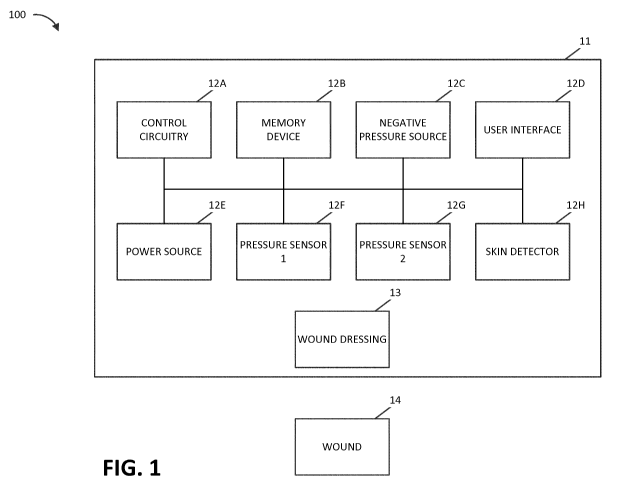
[0009] FIG. 1 illustrates a negative pressure therapy system according
to
some embodiments.
[0010] FIGS. 2A and 2B respectively illustrate a side view and top view
of
a negative pressure therapy system according to some embodiments, such as the
negative pressure therapy system of FIG. 1.
[0011] FIGS. 3, 4, 5A, and 5B illustrate top views of negative pressure
therapy systems according to some embodiments, such as the negative pressure
therapy system of FIGS. 2A and 2B.
[0012] FIG. 6 illustrates a therapy control process performable by a
negative pressure therapy system according to some embodiments.
[0013] FIGS. 7A, 7B, and 7C illustrate connectors according to some
embodiments.
[0014] FIGS. 8A and 8B illustrate top views of negative pressure
therapy
systems according to some embodiments, such as the negative pressure therapy
system of FIGS. 2A and 2B.
-4-
CA 03055664 2019-09-06
WO 2018/162613 PCT/EP2018/055698
[0015] FIGS. 9, 10, 11, and 12 illustrate components of negative
pressure
therapy systems according to some embodiments, such as the negative pressure
therapy system of FIGS. 2A and 2B.
DETAILED DESCRIPTION
[0016] The present disclosure relates to methods and apparatuses for
dressing and treating a wound with reduced pressure therapy or topical
negative
pressure (TNP) therapy. In particular, but without limitation, embodiments of
this
disclosure relate to negative pressure therapy apparatuses, methods for
controlling
the operation of TNP systems, and methods of using TNP systems. The methods
and apparatuses can incorporate or implement any combination of the features
described below.
[0017] Many different types of wound dressings are known for aiding in
the healing process of a human or animal. These different types of wound
dressings include many different types of materials and layers, for example,
gauze,
pads, foam pads or multi-layer wound dressings. TNP therapy, sometimes
referred
to as vacuum assisted closure, negative pressure wound therapy, or reduced
pressure wound therapy, can be a beneficial mechanism for improving the
healing
rate of a wound. Such therapy is applicable to a broad range of wounds such as
incisional wounds, open wounds and abdominal wounds or the like.
[0018] TNP therapy can assist in the closure and healing of wounds by
reducing tissue oedema, encouraging blood flow, stimulating the formation of
granulation tissue, removing excess exudates, and reducing bacterial load and
thus,
infection to the wound. Furthermore, TNP therapy can permit less outside
disturbance of the wound and promote more rapid healing.
[0019] As is used herein, reduced or negative pressure levels, such as
¨X
mmHg, represent pressure levels that are below atmospheric pressure, which
typically corresponds to 760 mmHg (or 1 atm, 29.93 inHg, 101.325 kPa, 14.696
psi,
etc.). Accordingly, a negative pressure value of ¨X mmHg reflects pressure
that is
X mmHg below atmospheric pressure, such as a pressure of (760¨X) mmHg. In
-5-
CA 03055664 2019-09-06
WO 2018/162613 PCT/EP2018/055698
addition, negative pressure that is "less" or "smaller" than ¨X mmHg
corresponds to
pressure that is closer to atmospheric pressure (e.g., ¨40 mmHg is less than
¨60
mmHg). Negative pressure that is "more" or "greater" than ¨X mmHg corresponds
to pressure that is further from atmospheric pressure (e.g., ¨80 mmHg is more
than
¨60 mmHg).
Overview
[0020] The user interfaces of some TNP apparatuses may have a limited
elements through which a user can provide user input. In some instances,
particular user interfaces may include just a single element usable by the
user to
stop and start delivery of negative pressure, and the user may not be able to
replace or interchange the single element with another element. These
particular
user interfaces can desirably be easier to construct and operate than more
complicated user interfaces having numerous elements. However, the particular
user interfaces may present a problem if the single element experiences a
fault (for
example, a failure) and is no longer able to function to receive user input.
The user
of the particular user interfaces may undesirably be unable to start delivery
of
negative pressure if negative pressure is not already being provided and stop
delivery of negative pressure if negative pressure is being provided.
[0021] The situation of a user being unable to stop delivery of
negative
pressure can additionally introduce risks to the healing of a wound of a
patient. If
the patient experiences discomfort from the wound dressing during delivery of
negative pressure and the single element experiences is no longer able to
function
to receive user input, the patient may be forced to remove the wound dressing
to
terminate delivery of negative pressure. The removal of the wound dressing can
damage the wound of the patient and hinder any healing trajectory that was
already
progressed, as well as exposing the wound to external contaminants due to a
loss
of protection from the wound dressing.
[0022] To address the situation of the user being unable to stop
delivery
of negative pressure, a TNP apparatus with the single element usable by the
user to
-6-
CA 03055664 2019-09-06
WO 2018/162613 PCT/EP2018/055698
stop and start delivery of negative pressure can include another mechanism,
such
as another redundant mechanism, to stop delivery of negative pressure. In some
implementations, a header circuit with four circuits could be used, and each
pair of
circuits could be used to deactivate operation by one or more means. One pair
of
the circuit could be used to connect to a power supply of the TNP apparatus,
and
the other pair of circuits could be used to connect to an enable signal (for
example,
a control circuitry enable signal). Additionally or alternatively, a surface
mount
technology (SMT) pin header could be used. The another mechanism can, for
instance, be an activating part molded in a film that may be welded to the
wound
dressing so that the activating mechanism may not be easily lost. Additionally
or
alternatively, the locking mechanism of a zero insertion force (ZIF) connector
may
be used to improve retention. The activating mechanism can, in another
example,
be a printed circuit board (PCB), such as a flexible PCB, built into a film
for
insertion. The activating mechanism can, in yet another example, include a
conductive label that completes the circuit when attached and is removable to
stop
delivery of negative pressure. In some implementations, a tab may additionally
or
alternatively be used, and the tab may, for instance, be pulled to disrupt a
power
supply for the TNP apparatus (such as to remove a battery) or pulled to rip an
aperture in the wound dressing (such as by pulling a tab on an outside of the
wound
dressing) to force a gross leak that causes termination of delivery of
negative
pressure.
Reduced Pressure Therapy Systems and Methods
[0023] FIG. 1 illustrates a negative pressure therapy system 100 that
includes a TNP apparatus 11 and a wound 14. The TNP apparatus 11 can be used
to treat the wound 14. The TNP apparatus 11 can include control circuitry 12A,
memory 12B, a negative pressure source 12C, a user interface 12D, a power
source 12E, a first pressure sensor 12F, a second pressure sensor 12G, and a
skin
detector 12H that are configured to electrically communicate with one another.
In
addition, the TNP apparatus 11 can include a wound dressing 13. The power
-7-
CA 03055664 2019-09-06
WO 2018/162613 PCT/EP2018/055698
source 12E can provide power to one or more components of the TNP apparatus
11.
[0024] One or more of the control circuitry 12A, memory device 12B,
negative pressure source 12C, user interface 12D, power source 12E, first
pressure
sensor 12F, second pressure sensor 12G, and skin detector 12H can be integral
with, incorporated as part of, attached to, or disposed in the wound dressing
13.
The TNP apparatus 11 can accordingly be considered to have its control
electronics
and pump on-board the wound dressing 13 rather than separate from the wound
dressing 13.
[0025] The control circuitry 12A can include one or more controllers,
activation circuits, boost converters, current limiters, feedback conditioning
circuits,
and H-bridge inverters. The one or more controllers can control the operations
of
one or more other components of the TNP apparatus 11 according at least to
instructions stored in the memory device 12B. The one or more controllers can,
for
instance, control operations of the negative pressure source 12C via a signal
input
(for example, a pulse width modulation of the signal) to the one or more H-
bridge
inverters, which in turn drive power from the power source 12E to the negative
pressure source 12C.
[0026] The negative pressure source 12C can include a pump, such as,
without limitation, a rotary diaphragm pump or other diaphragm pump, a
piezoelectric pump, a peristaltic pump, a piston pump, a rotary vane pump, a
liquid
ring pump, a scroll pump, a pump operated by a piezoelectric transducer, a
voice
coil pump, or any other suitable pump or micropump or any combinations of the
foregoing.
[0027] The user interface 12D can include one or more elements that
receive user inputs or provide user outputs to a patient or caregiver. The one
or
more elements that receive user inputs can include buttons, switches, dials,
touch
screens, or the like, and the one or more elements that provide user outputs
can
include activation of a light emitting diode (LED) or one or more pixels of
the display
or activation of a speaker or the like. In one example, the user interface 12D
can
-8-
CA 03055664 2019-09-06
WO 2018/162613 PCT/EP2018/055698
include a switch to receive a first user input (for instance, a negative
pressure
activation or deactivation input), an interface element to receive a second
user input
(for instance, a negative pressure disable input), and two LEDs to indicate an
operating status (for example, functioning normally, under fault condition, or
awaiting user input) of the TNP apparatus 11.
[0028] The first pressure sensor 12F can be used to monitor pressure
underneath the wound dressing 13, such as pressure in a fluid flow path
connecting
the negative pressure source 12C and the wound 14, pressure at the wound 14,
or
pressure in the negative pressure source 12C. The second pressure sensor 12G
can be used to monitor pressure external to the wound dressing 13. The
pressure
external to the wound dressing can be atmospheric pressure; however, the
atmospheric pressure can vary depending on, for instance, an altitude of use
or
pressurized environment in which the TNP apparatus 11 may be used.
[0029] The control circuitry 12A can control the supply of negative
pressure by the negative pressure source 12C according at least to a
comparison
between the pressure monitored by the first pressure sensor 12F and the
pressure
monitored by the second pressure sensor 12G. The control circuitry 12A can
include a controller, such as a microcontroller or microprocessor.
[0030] The skin detector 12H can be used to determine if the wound
dressing 13 has been placed over the wound 14. The skin detector 12H can, for
example, detect skin of a patient. The detection by the skin detector 12H can
confirm whether the wound dressing 13 is coupled to skin of the patient next
to the
wound 14. When skin is detected, this may indicate that activation of the TNP
apparatus 11 is intentional rather than unintentional and can thus be used to
prevent unintentional activation of the TNP apparatus 11 or an end-of-life
timer of
the TNP apparatus 11, such as during transportation or manufacture of the TNP
apparatus 11. In one example, if the skin detector 12H indicates to the
control
circuitry 12A that skin is detected, the control circuitry 12A can activate
the negative
pressure source 12C to supply negative pressure in response to receiving an
activation input via the user interface 12D. If the skin detector 12H, on the
other
-9-
CA 03055664 2019-09-06
WO 2018/162613 PCT/EP2018/055698
hand, indicates to the control circuitry 12A that skin is not detected, the
control
circuitry 12A may not activate the negative pressure source 12C to supply
negative
pressure in response to receiving an activation input via the user interface
12D.
The skin detector 12H can include one or more of a capacitive sensor, an
impedance sensor, an optical sensor, a piezoresistive sensor, a piezoelectric
sensor, an elastoresistive sensor, and an electrochemical sensor.
[0031] The
wound dressing 13 can include a wound contact layer, a
spacer layer, and an absorbent layer. The wound contact layer can be in
contact
with the wound 14. The wound contact layer can include an adhesive on the
patient
facing side for securing the dressing to the skin surrounding the wound 14 or
on the
top side for securing the wound contact layer to a cover layer or other layer
of the
wound dressing 13. In
operation, the wound contact layer can provide
unidirectional flow so as to facilitate removal of exudate from the wound
while
blocking or substantially preventing exudate from returning to the wound 14.
The
spacer layer can assist in distributing negative pressure over the wound site
and
facilitating transport of wound exudate and fluids into the wound dressing 13.
Further, the absorbent layer can absorb and retain exudate aspirated from the
wound 14.
[0032] The
control circuitry 12A can, in some instances, prevent supply of
negative pressure with the negative pressure source 12C. For example, the
control
circuitry 12A can prevent supply of negative pressure by deactivating
operation of
the negative pressure source, opening a vent positioned in the fluid flow
path, and
closing a valve positioned in the fluid flow path.
[0033] The
supply of negative pressure with the negative pressure source
12C can, in some instances, be disabled. For example, supply of negative
pressure
can be disabled by deactivating operation of the negative pressure source 12C
or
the control circuitry 12A, opening a vent positioned in the fluid flow path,
and
closing a valve positioned in the fluid flow path. In
some implementations,
deactivating operation of the negative pressure source 12C or the control
circuitry
12A can be performed by disconnection of power to the negative pressure source
-10-
CA 03055664 2019-09-06
WO 2018/162613 PCT/EP2018/055698
12C or the control circuitry 12A or withdrawal of an enable signal provided to
the
negative pressure source 12C or the control circuitry 12A.
[0034] The control circuitry 12A can monitor a duty cycle of the
negative
pressure source 12C. As is used herein, the "duty cycle" can reflect the
amount of
time the negative pressure source 12C is active or running over a period of
time. In
other words, the duty cycle can reflect time that the negative pressure source
12C is
in an active state as a fraction of total time under consideration. Duty cycle
measurements can reflect a level of activity of the negative pressure source
12C.
For example, the duty cycle can indicate that the negative pressure source 12C
is
operating normally, working hard, working extremely hard, etc. Moreover, the
duty
cycle measurements, such as periodic duty cycle measurements, can reflect
various
operating conditions, such as presence or severity of leaks, rate of flow of
fluid (for
instance, air, liquid, or solid exudate, etc.) aspirated from a wound, or the
like.
Based on the duty cycle measurements, such as by comparing the measured duty
cycle with a set of thresholds (for instance, determined in calibration), the
controller
can execute or be programmed to execute algorithms or logic that control the
operation of the system. For example, duty cycle measurements can indicate
presence of a high leak, and the control circuitry 12A can be programmed to
indicate this condition to a user (for instance, patient, caregiver, or
physician) or
temporarily suspend or pause operation of the source of negative pressure in
order
to conserve power.
[0035] When the TNP apparatus 11 may be used to treat the wound 14,
the wound dressing 13 can create a substantially sealed or closed space around
the
wound 13 and under the wound dressing 13, and the first pressure sensor 12F
can
periodically or continuously measure or monitor a level of pressure in this
space.
The control circuitry 12A can control the level of pressure in the space
between a
first negative pressure set point limit and at least a second negative
pressure set
point limit. In some instances, the first set point limit can be approximately
¨70
mmHg, or from approximately ¨60 mmHg or less to approximately ¨80 mmHg or
more. In some instances, the second set point limit can be approximately ¨90
-11-
CA 03055664 2019-09-06
WO 2018/162613 PCT/EP2018/055698
mmHg, or from approximately ¨80 mmHg or less to approximately ¨100 mmHg or
more.
[0036] FIG. 2A illustrates a side view of a negative pressure therapy
system 200, and FIG. 2B illustrates a top view of the negative pressure
therapy
system 200. The negative pressure therapy system 200 can be an example
implementation of the negative pressure therapy system 100.
[0037] In the negative pressure therapy system 200, the wound dressing
13 of the TNP apparatus 11 is shown as attached to the wound 14. Arrows depict
the flow of air through the wound dressing 13 and wound exudate from the wound
14. The TNP apparatus 11 can include an air exhaust 26 and a component area
25, such as a components housing or storage area for components of the TNP
apparatus 11 like one or more of the control circuitry 12A, memory device 12B,
negative pressure source 12C, user interface 12D, power source 12E, first
pressure
sensor 12F, second pressure sensor 12G, and skin detector 12H.
[0038] The user interface 12D of the negative pressure therapy system
200 can include a switch 21 (such as a dome switch), an interface element 22
(such
as an electrical contact), a first indicator 23 (such as a first LED), and a
second
indicator 24 (such as a second LED). The switch 21 can receive a negative
pressure activation or deactivation user input (for example, such as receiving
the
activation or deactivation user input in response to depression of the switch
21 for a
period of time, like from between 0.5 seconds and 5 seconds). The interface
element 22 can receive a negative pressure disable user input. The first
indicator
23 and the second indicator 24 can indicate an operating status like
functioning
normally, under fault condition, or awaiting user input. In some
implementations,
the switch 21 or the interface element 22 can couple to a power supply
connection
of the negative pressure source 12C or the control circuitry 12A (such as a
controller of the control circuitry 12A) or an enable signal of the negative
pressure
source 12C or the control circuitry 12A to activate or deactivate supply of
negative
pressure or disable supply of negative pressure. Additionally or
alternatively, a
-12-
CA 03055664 2019-09-06
WO 2018/162613 PCT/EP2018/055698
SMT pin header may be used to activate or deactivate supply of negative
pressure
or disable supply of negative pressure.
[0039]
Component parts of the wound dressing 13 of the negative
pressure therapy system 200 are illustrated to include an airlock layer 27, an
absorbing layer 28, and a contact layer 29. The airlock layer 27 can enable
air flow.
The absorbing layer 28 can absorb wound exudate. The contact layer 29 can be
soft and include silicon and be used to couple the TNP apparatus 11 to the
patient.
[0040] FIG.
3 illustrates a top view of a negative pressure therapy system
300, which can be a more detailed example implementation of the negative
pressure therapy system 200. The interface element 22 as shown can include an
activating part 31 that may be molded in the film welded at position 32 to the
wound
dressing 13. The activating part 31 can be used to receive the user input for
the
interface element 22.
[0041] FIG.
4 illustrates a top view of a negative pressure therapy system
400, which can be a more detailed example implementation of the negative
pressure therapy system 200. The interface element 22 as shown can include a
printed circuit board (PCB) 41 that may be flexible and built into a film for
insertion
and welded at position 42 to the wound dressing 13. The printed circuit board
41
can be used to receive the user input for the interface element 22. Moreover,
the
locking mechanism of a zero insertion force (ZIF) connector may be used to
improve
retention.
[0042] FIGS.
5A and 5B illustrate a top view of a negative pressure
therapy system 500, which can be a more detailed example implementation of the
negative pressure therapy system 200. The interface element 22 as shown can
include a conductive label 51 that can be used to complete an electrical
contact
when attached (see FIG. 5B) and disconnect the electrical contact upon removal
to
receive the user input for the interface element 22.
Moreover, the locking
mechanism of a ZIF connector may be used to improve retention.
[0043] FIG.
6 illustrates a therapy control process 600 usable to control
delivery of negative pressure therapy by an apparatus, such as the TNP
apparatus
-13-
CA 03055664 2019-09-06
WO 2018/162613 PCT/EP2018/055698
11. For convenience, the therapy control process 600 is described in the
context of
the TNP apparatus 11, but may instead be implemented in other systems
described
herein or by other systems not shown. The therapy control process 600 can be
performed, in some instances, by the control circuitry 12A of the TNP
apparatus 11.
[0044] At block 602, the therapy control process 600 can determine
whether a disable input was received from a user. The disable input may, for
instance, be received from the user via the interface element 22. In some
implementations, the disable input may not be provided by any user input to
the
TNP apparatus 11 other than via the interface element 22.
[0045] If the disable input was received, at block 604, the therapy
control
process 600 can disable supply of negative pressure. The supply of negative
pressure can, for instance, be disabled by deactivation of operation of the
negative
pressure source 12C or the control circuitry 12A, opening of a vent positioned
in the
fluid flow path, and closing of a valve positioned in the fluid flow path.
After block
604, the therapy control process 600 can end. In some implementations, after
block
604, the TNP apparatus 11 may no longer be activated by user input to the
switch
21, and the user may thus no longer be able to cause the TNP apparatus 11 to
generate negative pressure.
[0046] If the disable input was not received, at block 606, the therapy
control process 600 can determine whether an activation input was received
from
the user. The activation input may, for instance, be received from the user
via the
switch 21. In some implementations, the activation input may not be provided
by
any user input to the TNP apparatus 11 other than via the switch 21.
[0047] If the activation input was not received, the therapy control
process
600 can return to block 602 and again determine whether the disable input was
received from the user.
[0048] On the other hand, if the activation input was received, at
block
608, the therapy control process 600 can supply negative pressure. The supply
of
negative pressure can be performed by the negative pressure source 12C, and
the
negative pressure can be supplied to the wound dressing 13 via the fluid flow
path.
-14-
CA 03055664 2019-09-06
WO 2018/162613 PCT/EP2018/055698
[0049] At block 610, the therapy control process 600 can determine
whether a deactivation input was received from the user. The deactivation
input
may, for instance, be received from the user via the switch 21. In some
implementations, the deactivation input may not be provided by any user input
to
the TNP apparatus 11 other than via the switch 21.
[0050] If the deactivation input was received, at block 612, the
therapy
control process 600 can prevent the supply of negative pressure. The supply of
negative pressure can, for instance, be prevented by one or more of
deactivation of
operation of the negative pressure source 12C, opening of a vent positioned in
the
fluid flow path, and closing of a valve positioned in the fluid flow path.
After block
612, the therapy control process 600 can return to block 602 and again
determine
whether the disable input was received from the user.
[0051] If the deactivation input was received, at block 614, the
therapy
control process 600 can determine whether the disable input was received from
the
user. The disable input may, for instance, be received from the user via the
interface element 22. In some implementations, the disable input may not be
provided by any user input to the TNP apparatus 11 other than via the
interface
element 22. In some embodiments, block 614 is periodically executed while the
TNP apparatus 11 provides negative pressure wound therapy in order to
determine
if supply of negative pressure should be disabled.
[0052] If the disable input was not received, the therapy control
process
600 can return to block 608 and the supply of negative pressure can continue.
[0053] If the disable input was received, at block 616, the therapy
control
process 600 can disable supply of negative pressure. The supply of negative
pressure can, for instance, be disabled by deactivation of operation of the
negative
pressure source 12C or the control circuitry 12A, opening of a vent positioned
in the
fluid flow path, and closing of a valve positioned in the fluid flow path.
After block
616, the therapy control process 600 can end. In some implementations, after
block
616, the TNP apparatus 11 may no longer be activated by user input to the
switch
21, and the user may thus no longer be able to cause the TNP apparatus 11 to
-15-
CA 03055664 2019-09-06
WO 2018/162613 PCT/EP2018/055698
generate negative pressure. Additionally or alternatively, the TNP apparatus
11
may no longer be activated by user input to the switch 21 until an enable
input is
received, such as from the user via the interface element 22. In
some
implementations, the enable input may not be provided by any user input to the
TNP
apparatus 11 other than via the interface element 22.
[0054] In
some implementations of the therapy control process 600, the
supply of negative pressure may not stop by any user inputs other than the
deactivation input or the disable input.
[0055] FIGS.
7A, 7B, 7C illustrate connectors, which can be used with any
of the embodiments of the negative pressure system described herein. FIG. 7A
illustrates a header 700A with four circuits (or connectors) 70A, 70B, 70C,
and 70D
for connecting, for example, the switch 21 and the interface element 22 to
each pair
of circuits. FIG. 7B illustrates an SMT pin header 700B for connecting, for
example,
the switch 21 and the interface element 22. In some implementations, the
switch 21
can be connected to the connector 72A and the interface element 22 can be
connected to the connector 72B or vice versa. FIG. 7C illustrates a ZIF
connector
700C having a terminal 74 to which the switch 21 or the interface element 22
can be
connected. In some embodiments, two ZIF connectors 700C can be used for
connecting each of the switch 21 and interface element 22.
[0056] FIG.
8A illustrates a top view of a negative pressure therapy
system 800A, which can be a more detailed example implementation of the
negative
pressure therapy system 200. A tab 810A can be pulled to rip an aperture in
the
wound dressing to force a gross leak along the dotted line 820A that causes
termination of delivery of negative pressure. FIG. 8B illustrates a top view
of a
negative pressure therapy system 800B, which can be a more detailed example
implementation of the negative pressure therapy system 200. Tabs 810B can be
pulled to tear the wound dressing along the dotted line 820B to disrupt a
power
supply or electronics for the TNP apparatus (such as to remove a battery or
electrical components) that causes termination of delivery of negative
pressure.
-16-
CA 03055664 2019-09-06
WO 2018/162613 PCT/EP2018/055698
[0057] FIG. 9 illustrates components 900 of a negative pressure therapy
system, which can be a more detailed example implementation of the negative
pressure therapy system 200. The components 900 can illustrate that the
batteries
can be separated from control electronics, and the connection between the
batteries
and control electronics can be used as an activation function. The components
900
can include a surface mount connector 910 on an underside as illustrated.
[0058] FIG. 10 illustrates components 1000 of a negative pressure
therapy system, which can be a more detailed example implementation of the
negative pressure therapy system 200. The components 1000 can include a
surface mount connector 1010 on an upperside as illustrated. The components
1000 can illustrate that a main electric area can include a rigid PCB and have
a
connector on an uppermost surface to connect to a battery assembly.
[0059] FIG. 11 illustrates components 1100 of a negative pressure
therapy system, which can be a more detailed example implementation of the
negative pressure therapy system 200. The components 1100 can illustrate an
arrangement of repartitioned electronics relative to one or more other
embodiments.
The pump can be on one side, and batteries can be added as a pack. The pack
could have silicone underside to adhere to the wound dressing. The components
1100 can include a surface mount connector on an underside as illustrated.
[0060] FIG. 12 illustrates components 1200 of a negative pressure
therapy system, which can be a more detailed example implementation of the
negative pressure therapy system 200. The components 1200 can illustrate a top
of
a pump module with a surface mount connector 1210 still on an upperside.
Other Variations
[0061] Any value of a threshold, limit, duration, etc. provided herein
is not
intended to be absolute and, thereby, can be approximate. In addition, any
threshold, limit, duration, etc. provided herein can be fixed or varied either
automatically or by a user. Furthermore, as is used herein relative
terminology such
as exceeds, greater than, less than, etc. in relation to a reference value is
intended
-17-
CA 03055664 2019-09-06
WO 2018/162613 PCT/EP2018/055698
to also encompass being equal to the reference value. For example, exceeding a
reference value that is positive can encompass being equal to or greater than
the
reference value. In addition, as is used herein relative terminology such as
exceeds, greater than, less than, etc. in relation to a reference value is
intended to
also encompass an inverse of the disclosed relationship, such as below, less
than,
greater than, etc. in relations to the reference value. Moreover, although
blocks of
the various processes may be described in terms of determining whether a value
meets or does not meet a particular threshold, the blocks can be similarly
understood, for example, in terms of a value (i) being below or above a
threshold or
(ii) satisfying or not satisfying a threshold.
[0062] Features, materials, characteristics, or groups described in
conjunction with a particular aspect, embodiment, or example are to be
understood
to be applicable to any other aspect, embodiment or example described herein
unless incompatible therewith. All of the features disclosed in this
specification
(including any accompanying claims, abstract, and drawings), or all of the
steps of
any method or process so disclosed, may be combined in any combination, except
combinations where at least some of such features or steps are mutually
exclusive.
The protection is not restricted to the details of any foregoing embodiments.
The
protection extends to any novel one, or any novel combination, of the features
disclosed in this specification (including any accompanying claims, abstract
and
drawings), or to any novel one, or any novel combination, of the steps of any
method or process so disclosed.
[0063] While certain embodiments have been described, these
embodiments have been presented by way of example only, and are not intended
to
limit the scope of protection. Indeed, the novel methods and systems described
herein may be embodied in a variety of other forms. Furthermore, various
omissions, substitutions and changes in the form of the methods and systems
described herein may be made. Those skilled in the art will appreciate that in
some
embodiments, the actual steps taken in the processes illustrated or disclosed
may
differ from those shown in the figures. Depending on the embodiment, certain
of the
-18-
CA 03055664 2019-09-06
WO 2018/162613 PCT/EP2018/055698
steps described above may be removed, others may be added. For example, the
actual steps or order of steps taken in the disclosed processes may differ
from
those shown in the figure. Depending on the embodiment, certain of the steps
described above may be removed, others may be added. For instance, the various
components illustrated in the figures may be implemented as software or
firmware
on a processor, controller, ASIC, FPGA, or dedicated hardware. Hardware
components, such as processors, ASICs, FPGAs, and the like, can include logic
circuitry. Furthermore, the features and attributes of the specific
embodiments
disclosed above may be combined in different ways to form additional
embodiments, all of which fall within the scope of the present disclosure.
[0064] User
interface screens illustrated and described herein can include
additional or alternative components. These components can include menus,
lists,
buttons, text boxes, labels, radio buttons, scroll bars, sliders, checkboxes,
combo
boxes, status bars, dialog boxes, windows, and the like. User interface
screens can
include additional or alternative information.
Components can be arranged,
grouped, displayed in any suitable order.
[0065]
Although the present disclosure includes certain embodiments,
examples and applications, it will be understood by those skilled in the art
that the
present disclosure extends beyond the specifically disclosed embodiments to
other
alternative embodiments or uses and obvious modifications and equivalents
thereof,
including embodiments which do not provide all of the features and advantages
set
forth herein. Accordingly, the scope of the present disclosure is not intended
to be
limited by the specific disclosures of preferred embodiments herein, and may
be
defined by claims as presented herein or as presented in the future.
[0066]
Conditional language, such as "can," "could," "might," or "may,"
unless specifically stated otherwise, or otherwise understood within the
context as
used, is generally intended to convey that certain embodiments include, while
other
embodiments do not include, certain features, elements, or steps. Thus, such
conditional language is not generally intended to imply that features,
elements, or
steps are in any way required for one or more embodiments or that one or more
-19-
CA 03055664 2019-09-06
WO 2018/162613 PCT/EP2018/055698
embodiments necessarily include logic for deciding, with or without user input
or
prompting, whether these features, elements, or steps are included or are to
be
performed in any particular embodiment. The terms "comprising," "including,"
"having," and the like are synonymous and are used inclusively, in an open-
ended
fashion, and do not exclude additional elements, features, acts, operations,
and so
forth. Also, the term "or" is used in its inclusive sense (and not in its
exclusive
sense) so that when used, for example, to connect a list of elements, the term
"or"
means one, some, or all of the elements in the list. Further, the term "each,"
as
used herein, in addition to having its ordinary meaning, can mean any subset
of a
set of elements to which the term "each" is applied.
[0067] Conjunctive language such as the phrase "at least one of X, Y,
and
Z," unless specifically stated otherwise, is otherwise understood with the
context as
used in general to convey that an item, term, etc. may be either X, Y, or Z.
Thus,
such conjunctive language is not generally intended to imply that certain
embodiments require the presence of at least one of X, at least one of Y, and
at
least one of Z.
[0068] Language of degree used herein, such as the terms
"approximately," "about," "generally," and "substantially" as used herein
represent a
value, amount, or characteristic close to the stated value, amount, or
characteristic
that still performs a desired function or achieves a desired result. For
example, the
terms "approximately", "about", "generally," and "substantially" may refer to
an
amount that is within less than 10% of, within less than 5% of, within less
than 1%
of, within less than 0.1% of, and within less than 0.01% of the stated amount.
As
another example, in certain embodiments, the terms "generally parallel" and
"substantially parallel" refer to a value, amount, or characteristic that
departs from
exactly parallel by less than or equal to 15 degrees, 10 degrees, 5 degrees, 3
degrees, 1 degree, or 0.1 degree.
[0069] The scope of the present disclosure is not intended to be
limited by
the specific disclosures of preferred embodiments in this section or elsewhere
in
this specification, and may be defined by claims as presented in this section
or
-20-
CA 03055664 2019-09-06
WO 2018/162613 PCT/EP2018/055698
elsewhere in this specification or as presented in the future. The language of
the
claims is to be interpreted broadly based on the language employed in the
claims
and not limited to the examples described in the present specification or
during the
prosecution of the application, which examples are to be construed as non-
exclusive.
-21-