Note: Descriptions are shown in the official language in which they were submitted.
CA 03055775 2019-09-06
WO 2018/169842
PCT/US2018/021952
Micro Pump Systems and Processing Techniques
CLAIM OF PRIORITY
This application claims priority under 35 U.S.C. 119(e) to provisional U.S.
Patent Application 62/470,460, filed on March 13, 2017, entitled: "Micro Pump
Systems
and Processing Techniques" the entire contents of which are hereby
incorporated by
reference.
BACKGROUND
This specification relates to micro-based systems and more particularly to
micro
pump systems/devices.
Mechanical pump systems and compressor systems are well-known. Pumps are
used to move fluid (such as liquids or gases or slurries) by mechanical
action. Pumps can
be classified according to the method used to move the fluid, e.g., a direct
lift pump, a
displacement pump, a peristaltic pump, and a gravity pump. Micro pumps are now
also
known. One example of a micro pump is described in my published application US-
2015-0267695-Al, published Sept. 24, 2015 filed Feb. 26, 2015 the entire
contents of
which are incorporated herein by reference. Techniques for fabricating such
micro
pumps are also disclosed in the above mentioned published application. Also
disclosed
in my published application US-2016-0131126-AL published May 12, 2016 and
filed
Oct. 29, 2015 the entire contents of which are incorporated herein by
reference, are
additional micro pump examples, exemplary applications and
microelectromechanical
systems (MEMS) fabrication techniques including roll to roll processing.
SUMMARY
Described are peristaltic micro pump systems. Exemplary techniques to
fabricate
such peristaltic micro pump systems include using lithographic etching and
patterning
techniques as well as roll to roll fabrication techniques.
1
CA 03055775 2019-09-06
WO 2018/169842
PCT/US2018/021952
The described peristaltic micro pump systems are provided by cascade
connecting
individual micro pump units. These units do not include internal, fixed inlet
and outlet
valve members/structures such as those disclosed in the above applications. By
operating
the individual micro pump units in a phased sequence, such operation can
effectively
provide inlet and outlet isolation functions, thus obviating the need for
fixed internal inlet
valve structures and outlet valve structures.
According to an aspect, a micro pump includes a plurality of micro pump
elements, each micro pump element including a pump body having walls that
enclose a
pump chamber that is compartmentalized into plural compartments, a plurality
of inlet
ports each with unobstructed fluid ingress into corresponding ones of the
plural
compartments and a plurality of outlet ports each with unobstructed fluid
egress from
corresponding ones of the plural compartments, a plurality of membranes
disposed in the
pump chamber, with the plurality of membranes affixed to the walls of the pump
body,
and which compartmentalized the chamber to provide the plural compartments,
and a
plurality of electrodes, with a first pair of the plurality of electrodes
disposed on a pair of
opposing walls of the pump body, and each of the remaining ones of the
plurality of
electrodes disposed on a major surface of a corresponding one of the plurality
of
membranes, with the plurality of micro pump elements arranged in a series
connected
configuration that has outlets of a first one of the plurality of micro pump
elements
fluidly connected to inlets of an immediately adjacent one of the plurality of
micro pump
elements.
Other aspects include methods of manufacture and methods of use.
The details of one or more embodiments of the invention are set forth in the
accompanying drawings and the description below. Other features, objects, and
advantages of the invention are apparent from the description and drawings,
and from the
claims.
2
CA 03055775 2019-09-06
WO 2018/169842
PCT/US2018/021952
DESCRIPTION OF DRAWINGS
FIG. 1 is an assembled cross-sectional view of a valve less micro pump
element.
FIGS. 1A and 1B are cross-sectional views (somewhat simplified) of the micro
pump element of FIG. 1 showing membrane actuations.
FIG. 1C is a blown-up view of a portion of FIG. 1A.
FIGS. 1D and 1E are cross-sectional views of an alternative configuration of a
micro pump element having tapered sidewalls for pump compartments, and showing
membrane actuations.
FIG. 1F is a blown-up view of a portion of FIG. 1D.
FIG. 2 is a cross-sectional view of an exemplary "valve less" micro pump
comprised of plural valve less micro pump elements in a series cascaded
connection
arrangement.
FIG. 2A is a cross-sectional view of an alternative configuration of a "valve
less"
micro pump.
FIG. 3 is a perspective partial view of a stack of module layers that provide
a
micro pump element.
FIG. 4 is an exploded view of an intermediate module layer on an endcap module
layer.
FIG. 4A is a perspective view of a portion of FIG 4.
FIG. 5 is an exploded view of an intermediate module layer.
FIGS. 6A and 6B are plots of waveforms of signals applied to electrodes
showing
phases for a peristaltic pumping sequence using the valve less micro pump of
FIG. 2.
FIGS. 7A to 7F are diagrams depicting series configured "valve less" micro
pump
of FIG. 2 operation according to the phases for the peristaltic pumping
sequence.
FIG. 8 is a functional block diagram of exemplary circuitry for the micro
pump.
FIGS. 9A-9C are views of a roll to roll implementation for constructing valve
less
micro pump elements.
3
CA 03055775 2019-09-06
WO 2018/169842
PCT/US2018/021952
DETAILED DESCRIPTION
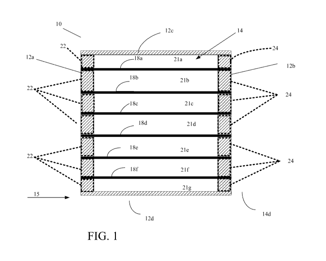
Referring now to FIG. 1, a micro pump stack element 10 includes a pump body
12 enclosing a single, compartmentalized pump chamber 14. The pump body 12 is
defined by two fixed walls 12a, 12b and two fixed end walls 12c, 12d opposite
to each
other and along a direction perpendicular to the two walls 12a, 12b. There are
also two
opposing walls (not shown in FIG. 1, which are orthogonal to fixed walls 12a,
12b and
fixed end walls 12c, 12d, all of which together form a cube-like structure.)
The pumping direction is shown by arrow 15. However, as explained below, the
pump direction is dynamically reversible. That is, as will be discussed below
the
designation of ports as inlets or outlets is with respect to drive sequences.
The walls 12a,
12b, 12c and 12d, and the two walls (not shown) of the pump body define the
single
chamber 14. The single chamber 14 is compartmentalized by membranes 18a-18f
that
are anchored or affixed to two opposing walls, e.g., the two walls 12c, 12d
(also referred
to herein as endcaps 12c, 12d). The membranes 18a-18f are disposed to extend
from the
wall 12a to the wall 12b and the two walls that are not shown in this view.
The
membranes 18a-18f separate the pump chamber 14 into seven compartments 21a-
21g.
(In an implementation, the walls 12a, 12b, 12c and 12d of the pump body are
provided by
stacking of micro pump modules as will be discussed below.)
In this implementation, each compartment 21a-21g includes a pair of ports 22,
24.
For discussion purposes, an inlet is generally designated as 22 and an outlet
is generally
designated as 24. These ports 22, 24 are illustrated in phantom in FIG. 1, as
the ports are
not visible in the cross-sectional view of FIG. 1. These ports 22, 24 are
passages through
the walls 12a, 12b, and more particularly an absence of portions of the walls
12a, 12b,
respectively. The ports 22, 24 can be either input ports or output ports
according to a
pump drive sequence that is used. Throughout this discussion inlets or inputs
are referred
to by the number 22 and outlets or outputs are referred to by the number 24.
For example, the compartment 21a includes inlet 22 in the wall 12a and outlet
24
in the wall 12b, with the compartment 21a being defined by a portion of the
wall 12a, the
wall (or endcap) 12c, a portion of the wall 12b, the two walls (not shown in
FIG. 1), and
4
CA 03055775 2019-09-06
WO 2018/169842
PCT/US2018/021952
the membrane 18a. Other inlets and outlets are also labeled 22 and 24
respectively and
other ones of the compartments 21b-21g are defined similarly.
The compartment 21g (like compartment 21a) at the opposite end of the pump
chamber 14 is defined by the fixed wall (or endcap) 12d of the pump body 12,
the two
walls (not shown), and the corresponding membrane 18f All intermediate
compartments
21b-21f between the compartments 21a, 21g have walls formed by two membranes
and
corresponding portions of the walls 12a and 12b and the two walls (not shown).
In some
embodiments of the micro pump stack element 10, there is at least one
intermediate
compartment defined by portions of walls 12a, 12b and two membranes. Although
six
membranes (and five intermediate compartments) are shown in the figures, the
pump
chamber can be extended or reduced with additional or fewer intermediate
compartments.
The compartments 21a-21g are fluidically isolated from each other.
An electrode (not explicitly shown in FIG. 1 to FIG. 1F, but which will be
discussed in FIGS. 2, 2A, and FIGS. 3-5) is attached to one side of each of
the
membranes 18a-18g and optionally to the end walls 12c, 12d. The electrodes are
connected to a drive circuit (see FIG. 8) that delivers voltages to the
electrodes to activate
the respective membranes, e.g., causing flexing of the membranes, through
electrostatic
attraction/repulsion.
Without activation, the membranes rest at nominal positions as shown in FIG.
1.
Each membrane at rest can be substantially parallel to the end walls 12c, 12d
and the
compartments 21b-21f can have the same nominal volume V,. In some
implementations,
the compartments 21a and 21g each have the same nominal volume Vi, which is
about
half of the nominal volume V. For example, the distance between two adjacent
membranes in their nominal positions is about 50 microns, and the nominal
volume V,
can range from nanoliters to microliters to milliliters, e.g., 0.1
microliters.
In the implementations, where the compartments 21a, 21g each have the nominal
volume Vj that is half the nominal volume of the intermediate compartments 21b-
21f, the
distance between the membrane 18a, 18g in their nominal positions and the end
walls 12c
or 12d is about 25 microns. The nominal volume V can range from nanoliters to
microliters to milliliters, e.g., 0.05 microliters. The compartments can also
have different
5
CA 03055775 2019-09-06
WO 2018/169842
PCT/US2018/021952
dimensions. The dimensions are chosen based on, e.g., specific process
requirements, as
well as, power consumption, application considerations and so forth.
For example, the compartments 21a, 21b having a width of 25 microns can allow
a start-up function with a reduced peak drive voltage. Drive voltages are
discussed
further below. As an example, the micro pump element 10 can have an internal
volume
having a length of about 1.5mm, a width of about 1.5 mm, a total height (the
cumulative
height of different compartments) of 0.05mm, and a total volume of about
0.1125 1.
One application of the micro pump element 10 is as a basic unit to build a
series
connected micro pump of which a peristaltic micro pump is a specific example,
all of
which is discussed in FIG. 2 (below).
FIGS. 1A and 1B show two operational states of the micro pump stack element
10. When actuated, each membrane of the pump chamber flexes in one of two
opposite
directions about a central, nominal location at which the membrane is at a
rest state when
it is not actuated, according to polarities of voltages provided to electrodes
(not shown)
on membranes and endcaps. The rest positions of the membranes are shown in
phantom
dotted lines in each of FIGS. 1A and 1B.
Voltages are applied to the membranes 18a-18f according to a sequence. In
response to a one portion of such as sequence, a compartment, e.g.,
compartment 21a, is
compressed when the adjacent membrane 18a defining that compartment moves
towards
the endcap 12c (see FIG. 1A) carrying an electrode (not shown), reducing the
volume of
the compartment 21a and isolating the compartment 21a via a seal 28 (where the
membrane 18a contacts the endcap 12c) to discharge a fluid, e.g., a gas or a
liquid from
the compartment 21a. The membrane 18a and endcap 12c form a seal that isolates
one of
the ports (generally 22 shown in phantom) from the opposite ports (generally
24 shown in
phantom), as shown in FIG. 1C. Simultaneous to the compression of that
compartment,
e.g., 21a, the immediately adjacent compartment, e.g., compartment 21b, is
charged when
its two membranes 18a and 18b move away from each other to expand the
compartment
21b volume (see FIG. 1A) that removes a seal that had isolated, e.g., port 22
(shown in
phantom) from the port 24 (shown in phantom), in a previous sequence of
application of
the voltages.
6
CA 03055775 2019-09-06
WO 2018/169842
PCT/US2018/021952
FIG. 1B shows a second operational state of the membranes when voltage
polarities are changed. Ports are not illustrated. The membranes are
illustrated but not
referenced.
As shown in FIGS. 1, 1A-1B the walls of the pump body are perpendicular to the
nominal resting positions (see FIG. 1) of the membranes. However, if the walls
of the
pump body are perpendicular, there may exist small void spaces 25 (e.g., FIG.
1A)
between the walls of the pump body and membranes, as shown in FIGS. 1A-1B.
Within
this void 25 could reside a small amount of the fluid being pumped by the
micro pump
10. This fluid would remain each cycle as the fluid is pumped by the micro
pump, and
thus the presence of the voids 25 may represent a loss in pumping efficiency.
Referring now to FIGS. 1D-1E, in order to alleviate the potential loss caused
by
voids 25, the walls of the pump body could be configured to gradually taper
(either a
straight line taper, as shown or a curved line taper) having a generally
equilateral
triangular, solid shape into the chamber as shown in FIGS. 1D-1F to
substantially fill the
voids 25 (e.g., eliminate the voids shown in FIGS. 1A-1B). The walls of the
pump body
12 can be of a shape 23, e.g., a wedge-shape, that will occupy any space that
would
remain after a membrane flexed in response to application of voltages. That
is, upon
application of voltage to the electrodes, electrostatic attraction of
membranes having
opposite electrostatic charges will have the membranes initially touch in the
middle and
subsequently cause the membranes to "zipper" together as the attraction force
towards
each other causes the membranes to further flex and fully seal against the
tapered
portions of the pump body walls and surfaces of the membrane.
Referring now to FIG. 2, a series configuration micro pump 30 (series
configuration 30) comprising a plurality of micro pump elements 10a-10c will
now be
described. In the series configuration 30 three elements 10a-10c are shown.
However, a
given series configuration requires at least three but can comprise more than
three
elements. The micro pump elements 10a-10c each have a pump body (not
referenced,
but see FIG. 1) having a pump chamber (not referenced, but see FIG. 1) that is
compartmentalized into plural compartments (not referenced, but see FIG. 1),
with the
plural compartments having inlet ports providing unobstructed fluid ingress
into the
7
CA 03055775 2019-09-06
WO 2018/169842
PCT/US2018/021952
compartments and outlet ports providing unobstructed fluid egress from the
compartments. A plurality of membranes 18a-18f is disposed in the pump
chamber, the
membranes 18a-18f are anchored between opposing walls (not referenced, but see
FIG.
1) of the pump body to provide the plural compartments. The membranes support
electrodes (generally 27) that are segmented by stage (see FIG. 2A) and
disposed on a
major surface of each of the membranes 18a-18g (and optionally on the body, as
shown).
The plurality of micro pump elements 10a-10c are arranged in the series
configuration
with outlets of a first one of the plurality of micro pump elements 10a-10c
being fluidly
connected to inlets of an adjacent one of the plurality of micro pump elements
10a-10c.
The series configuration of plural micro pump elements 10a-10c (using the
stack
10 of FIG. 1) provides a "valve-less" series configuration 30. A "valve-less"
micro pump
is defined as a micro pump comprised of three or more micro pump units that
have no
physical valve elements for inlets and outlets. That is, a valve-less micro
pump has a
configuration that effectively provides inlet and outlet isolation during
pumping without
individual physical valve structure elements built into the micro pump stack
elements
10a-10c, e.g., at inlet and/or outlet ports and without individual physical
valve structure
elements between adjacent micro pump stack elements.
In the series configuration 30, each of the plural micro pump stacks 10a-10c
has
pairs of ports. These ports operate as either inlets or outlets or in some
implementations
can be i/o (inlet/outlet) ports that can change function (inlet or outlet)
dynamically and
pump accordingly. For discussion purposes inlet ports are referred to as 22
and outlet
ports are referred to as 24. These ports 22, 24 are illustrated in phantom in
FIG. 2, as the
ports are not visible the view of FIG. 2.
The series configuration 30 of the micro pump elements 10a-10c shows the inlet
ports 22 and the outlet ports 24 on opposing walls of the pump body. This is
generally
desirable, but not necessarily a requirement. Also in the series configuration
30, the
micro pump stacks 10a and 10c operate as either input stages or output stages
or I/0
(input/output) pump stages whose functions can be changed dynamically, and the
micro
pump stack 10b being the middle stack operates as an interior isolation pump
stage. The
inlet ports 22 of the input stage 10a connect to a source of fluid and the
outlet ports 24 of
8
CA 03055775 2019-09-06
WO 2018/169842
PCT/US2018/021952
a last one of the micro pump elements 10a-10c are configured to connect to a
sink to
store pressurized fluid from the micro pump.
For discussion purposes, inlets are generally 22 and outlets are generally 24
and
stage 10a is an input stage and 10c is an output stage. Thus, inlets 22a of
the micro pump
stack 10a are fluidly coupled to a source of fluid, such as a liquid or gas,
e.g., ambient air.
Outlets 24a of the micro pump stack 10a are fluidly coupled to inlets 22b of
the micro
pump stack 10b. Outlets 24b of the micro pump stack 10b are fluidly coupled to
inlets
22c of the micro pump stack 10c and outlets 24c of the micro pump stack 10c
are fluidly
coupled to a sink for fluid pumped through the pump. This sink can be
pressurized air
from the ambient that is blown out of the micro pump or stored for instance in
a tank (not
shown).
Each of the micro pump stacks 10a-10c are driven using circuity discussed
below
and driven according to phases such as those of FIGS. 6 and 7A-7F.
Compared to a conventional pump used for similar purposes, the series
configuration 30 and the micro pump elements 10a-10c use less material that is
subject to
less stress, and are driven using less power. The series configuration 30 has
a size in the
micron to millimeter scale, and can provide wide ranges of flow rates and
pressure.
Generally, the flow rate can be in the scale of microliters to milliliters. An
approximate
flow rate provided by a micro pump can be calculated as:
Flow Rate is given approximately by the total volume of
the micro pump x drive frequency x (1-loss factor).
Generally, the pressure is affected by how much energy, e.g., the drive
voltage, is
put into the micro pump 30. In some implementations, the higher the voltage,
the larger
the pressure. The upper limit on voltage is defined by break down limits of
the series
configuration 30 and the lower limit on the voltage is defined by a membrane's
ability to
sufficiently flex in response to the voltage. The pressure across a series
configuration 30
can be in the range of about micro psi to tenths of a psi. A selected range of
flow rate and
pressure can be accomplished by selection of pump materials, pump design, and
pump
manufacturing techniques.
9
CA 03055775 2019-09-06
WO 2018/169842
PCT/US2018/021952
One described version of the series configuration 30 is a peristaltic type
pump in
the displacement type category. In one implementation, pumping occurs
according to six
phases, as set out in FIGS. 6 and 7A-7F, discussed below.
In operation, the membrane of a conventional pump (not including the micro
pump discussed in the above incorporated by reference application) typically,
the pump
has a single pump chamber that is used in pumping. Gas is charged and
discharged once
during the charging and discharging operations of a pumping cycle,
respectively. The
gas outflows only during half of the cycle, and the gas inflows during the
other half of the
cycle.
In the instant series configuration 30 each compartment is used in pumping.
For
example, two membranes between two fixed end walls form three compartments for
pumping. The micro pump can have a higher efficiency and can consume less
energy
than a conventional pump performing the same amount pumping, e.g., because the
individual membranes travel less distance and therefore are driven less. The
efficiency
and energy saving scales as the number of membranes and compartments between
the
two fixed end walls increases.
Generally, to perform pumping, each compartment includes a gas inlet and a gas
outlet. The inlet and the outlet are valve-less, e.g., there are neither
passive nor active
valves that open or close in response to pressure applied to the valves, in
contrast to the
embodiments discussed in the above incorporated by reference application.
Referring now to FIG. 2A, in one alternative embodiment of a valve less series
configuration micro pump 30', the series configuration of FIG. 2 can be
effectively
provided by a single one of the stack elements 10 of FIG. 1 (elongated in this
view). In
this alternative configuration, the micro pump 30' is again "valve-less" and
is produced
from a single pump body 12 having two fixed walls 12a, 12b and two fixed end
walls
12c, 12d opposite to each other and along a direction perpendicular to the two
walls 12a,
12b together with two opposing walls (not shown in FIG. 2A, which are
orthogonal to
fixed walls 12a, 12b and fixed end walls 12c, 12d, all of which together form
a cube-like
structure) with intermediate walls 13a, 13b to provide tympanic support for
membranes
(not referenced).
CA 03055775 2019-09-06
WO 2018/169842
PCT/US2018/021952
In this alternative series configuration 30', the micro stack generally 10
effectively has three stages of a general stack 10 and has pairs of ports
generally 22 and
24.
The effective three stages of the general stack 10 is provided by a specific
patterned
electrode element 27 on the membranes and end caps (not referenced, but see
FIG. 2).
The ports can operate as either inlets or outlets or in some implementations
can be i/o
(inlet/outlet) ports that can change function dynamically. Electrodes
(generally 27) are
shown on the membranes (not referenced) as well as end electrodes on outer
surfaces of
the body. Alternatively, these electrodes could be within the body, provided
that an
insulating layer is used over any one of the end electrodes that could come in
contact with
an intermediate one of those electrodes.
Also in this series configuration 30' the specific patterned electrode element
27
comprises three, spaced and electrically isolated electrode regions 27a, 27b,
27c. These
electrode regions are activated according to the same phases and signals
discussed below.
Presuming that the micro pump stack 10 has a suitable aspect ratio of width of
electrode
regions to height of compartments that is sufficiently low to enable the
membrane to flex
in three regions, similar to the arrangement of FIG. 2, the electrode regions
27a and 27c
can operate the stack 10 to provide the input stages or output stages or I/O
(input/output)
stages, and the electrode region 27b can operate the stack 10 as the pump
stage.
In the implementation of FIG. 2 (and FIG. 2A), the absence of mechanical valve
devices requires another mechanism to maintain a differential pressure created
by flow of
gas in or out of a pump compartment. In this implementation of the micro pump
element
10 actual mechanical valves elements are eliminated as the input/output stages
are used
for isolation (i.e. a valve function) in the series configuration of multiple
micro pump
element stages 10a-10c. Because no valves are required, the absence of such
valves can
reduce complications of pump fabrication and cost. In addition, unlike the
embodiments
discussed in the above incorporated by reference applications the mechanism
discussed
herein to maintain differential pressure created by flow of gas in or out of a
pump
compartment also obviates the need for nozzles and diffusers as mentioned in
the
incorporated by reference application as an alternative "valve-less"
implementation that
would use nozzles and diffusers. This mechanism is provided by the arrangement
of FIG.
11
CA 03055775 2019-09-06
WO 2018/169842
PCT/US2018/021952
2 in which micro pump elements 10a and 10c provide ports (interchangeably
input/output
ports) and micro pump element 10b is the actual pump element.
The membranes are driven to move (flex) by electrostatic force. An electrode
is
attached to each of the fixed end walls and the membranes. During the charging
operation of a compartment, two adjacent electrodes of the compartment have
the same
positive or negative voltages, causing the two electrodes and therefore, the
two
membranes to repel each other. During the discharging operation of a
compartment, two
adjacent electrodes of the compartment have opposite positive or negative
voltages,
causing the two electrodes and therefore, the two membranes to attract to each
other.
This is evident in FIGS. 1A and 1B. In this implementation of the micro pump
it is
desired to drive the membranes such that flexure of the membranes cause each
set of
membranes that constrict a compartment to seal that compartment, as denoted by
reference 28 in FIG. 1C and reference 29 in FIG. 1F.
The two electrodes of a compartment form a parallel plate electrostatic
actuator.
The electrodes generally have small sizes and low static power consumption. A
high
voltage can be applied to each electrode to actuate the compartment while the
actuation is
performed at a relatively low current.
As described previously, each membrane of the micro pump moves in two
opposite directions relative to its central, nominal position. Accordingly,
compared to a
compartment in a conventional pump, to expand or reduce a compartment by the
same
amount of volume, the membrane of this specification travels a distance less
than, e.g.,
half of, the membrane in the conventional pump. As a result, the membrane
experiences
less flexing and less stress, leading to longer life and allowing for greater
choice of
materials. The starting drive voltage for the electrode on the membrane needs
be
sufficient to drive the membranes such that each travels at least half of the
distance or
over half the distance, which would slightly flatten the membranes where a
pair of driven
membranes touched. For a compartment having two membranes, since both
membranes
are moving, the time it takes to reach the pull-in voltage can be shorter.
Microelectromechanical systems such as micro pumps having the above described
features are fabricated using roll to roll (R2R) processing. Roll-to-roll
processing is
12
CA 03055775 2019-09-06
WO 2018/169842
PCT/US2018/021952
becoming employed in manufacture of electronic devices using a roll of
flexible plastic
or metal foil as a base or substrate layer. Roll to roll processing has been
used in other
fields for applying coatings and printing on to a flexible material delivered
from a roll
and thereafter re-reeling the flexible material after processing onto an
output roll. After
the material has been taken up on the output roll or take-up roll the material
with coating,
laminates or print materials are diced or cut into finished sizes.
Below are some example criteria for choosing the materials of the different
parts
of the micro pump.
Pump body ¨ The material used for the body of a pump needs to be strong or
stiff
enough to hold its shape to provide the pump chamber volume. In some
implementations, the material is etch-able or photo-sensitive so that its
features can be
defined, machined and/or developed. Sometimes it is also desirable that the
material
interact well, e.g., adheres with the other materials in the micro pump.
Furthermore, the
material is electrically non-conductive. Examples of suitable materials
include 5U8
(negative epoxy resist), and PMMA (Polymethyl methacrylate) resist,
Polyvinylidene
fluoride (PVDF), Polyethylene terephthalate (PET), Polytetrafluoroethylene
(PTFE) such
as Teflon The Chemours Company.
Membrane ¨ The material for this part forms a tympanic structure (a thin tense
membrane covering the pump chamber) that is used to charge and discharge the
pump
chamber. As such, the material is required to bend or stretch back and forth
over a
desired distance and has elastic characteristics. The membrane material is
impermeable
to fluids, including gas and liquids, is electrically non-conductive, and
possesses a high
breakdown voltage. Examples of suitable materials include silicon nitride and
Polyvinylidene fluoride (PVDF), Polyethylene terephthalate (PET),
Polytetrafluoroethylene (PTFE) such as Teflon The Chemours Company.
Electrodes ¨ These structures are very thin and comprised of material that is
electrically conductive. Because the electrodes do not conduct much current,
the material
can have a high electrical sheet resistance, although the high sheet
resistance feature is
not necessarily desirable. The electrodes are subject to bending and
stretching with the
membranes, and therefore, it is desirable that the material is supple to
handle the bending
13
CA 03055775 2019-09-06
WO 2018/169842
PCT/US2018/021952
and stretching without fatigue and failure. In addition, the electrode
material and the
membrane material will need to adhere well to each other, e.g., will not
delaminate from
each other, under the conditions of operation. Examples of suitable materials
include
aluminum, gold, and platinum.
Electrical interconnects ¨ The drive voltage is conducted to the electrode on
each
membrane of each compartment. Electrically conducting paths to these
electrodes can be
built using conductive materials, e.g., aluminum, gold, and platinum.
Referring now to FIGS. 3- 5, a modularized "valve-less" series configuration
30
comprised of a series configuration (not shown in these figures) of micro pump
elements
is shown.
Referring to FIG. 3, module layers 42 can be series connected (not shown) and
stacked (as shown) to provide a stack of the compartments (not referenced) for
a given
micro pump element to provide a modularized micro pump element 10'. The
modularized micro pump element 10' is comprised of many module layers 42 (FIG.
3)
that form intermediate compartments of the micro pump element 10' and plural
micro
pump elements 10' can be series connected as well as end compartments to
provide a
modularized micro pump stack (not shown in FIG. 3). The modularized micro pump
element 10' is similar to that described in the above mentioned incorporated
by reference
published application, except that the present modularized micro pump element
10'
eliminates the valve devices used with the micro pump stack in the above
mentioned
incorporated by reference published application. The modularized micro pump
element
10' arranged in a series configuration of micro pump stack elements 10',
similar to that
discussed above for elements 10.
Specific details on modularized micro pump fabrication using silicon based
lithographic as well as roll to roll processing are discussed below.
Referring now to FIG. 4, a pump end cap 44 forming a fixed pump wall (similar
to walls 12c, 12d FIGS. 1A, 1B). An electrode 48 is attached to the pump end
cap 44 for
activating a compartment 49. A single module layer 42 forms a portion of a
pump body
50 between the pump end cap 44 with the electrode 48, and a membrane 52 along
with an
electrode 54 that is attached to the membrane 52 on the opposite side of the
pump body
14
CA 03055775 2019-09-06
WO 2018/169842
PCT/US2018/021952
50 (similar as the membranes in FIGS. 1A, 1B). The electrode 54 includes a
lead 55 to
be connected to a drive circuit external to the module layer 42. FIG. 4A shows
tapered
walls of an alternative for the pump body 50.
The membrane 52, the pump end cap 44, and the pump body 50 can have the
same dimensions, and the electrodes 48, 54 can have smaller dimensions than
the
membrane 52 and the other elements. In some implementations, the membrane 52
has a
dimension in a range of about a hundred microns to millimeters up to about
several
centimeters for thicknesses of about 5 microns. For thinner membranes, the
dimensions
can be smaller. The limit on the low end of the thickness range is up to where
there is no
permanent deformation of the membrane. For the higher end of the thickness
range the
limit is where membrane remains tympanic. The pump body 50 would have
corresponding dimensions. The thickness of the pump body defines the nominal
size of
the compartment 49 (similar to compartments FIG. 1A). The electrodes 48, 54
have
dimensions that substantially correspond to inner dimensions of the pump body
50. In
some implementations, the electrodes 48, 54 have a surface area of about 2.25
mm2 and a
thickness of about 0.15 microns. Although the electrodes are shown as a pre-
prepared
sheet to be attached to the other elements, the electrodes can be formed
directly onto
those elements, e.g., by printing. The different elements of the module layers
can be
bonded to each other using an adhesive. In some implementations, a solvent can
be used
to partially melt the different elements and adhere them together or laser
welding or
ultrasonic welding can also be used.
Referring to FIG. 5, intermediate compartments are formed using a module layer
42. The module layer 42 includes a pump body 50, an electrode 54, and a
membrane 52
formed between the electrode 54 and the pump body 50. The assembled module
layers
have unobstructed apertures that provide inlets and outlets and provided
unobstructed
paths through the pump body 50 and the compartment. A pressure differential is
established with the configuration discussed above in FIG. 2. Multiple, e.g.,
two, three,
or any desired number of, module layers of FIG. 5 are stacked on top of each
other to
form multiple intermediate compartments in a pump chamber. In the stack 40,
each
membrane is separated by a pump body and each pump body is separated by a
CA 03055775 2019-09-06
WO 2018/169842
PCT/US2018/021952
membrane. To form a complete pump (such as a micro pump element 10), a module
layer of FIG. 4 (end cap module) is placed on each of the top and bottom ends
of the
stack so that the pump end caps of the module layer form two fixed end walls
of the
pump chamber.
A charging operation is established when pressure external to a module layer
is
larger than pressure inside the module layer, and thus a fluid flows from
outside the
module layer into the compartment. When the internal pressure is higher than
the
external pressure, a discharge operation is established and fluid flows from
the
compartment away to the outside of the module layer. Discharge occurs by
displacement
meaning that the pump can discharge fluid at ambient pressure. During the
discharge
operation, the fluid in the compartment does not flow out from the inlet due
to the
configuration, as driven as discussed below. Effectively, during the charging
operation,
the outlet is closed so that the fluid does not flow out of the compartment,
and during the
discharging operation, the outlet is open and the fluid flows out of the
compartment.
Referring now to FIGS. 6A, 6B, timing waveforms for a peristaltic sequence are
shown. As shown there are six phases to form a sequence that repeats. FIG. 6A
shows a
true phase and FIG. 6B shows the complement of the true phase, which together
provide
for six signals 51, 51' S2, S2' and S3, S3' to drive respective groups of
membranes, as
more fully explained in FIGS. 7A-7F. The timing waveforms represent when a
stage is
open (logic 0) and when a stage is closed (logic 1). A clock signal is also
shown.
Referring now to FIGS. 7A-7F, states of each of the compartments in each of
the
stages in the series configuration 30 are shown. I/0 ports while present, are
not shown in
these figures. In each figure the peristaltic sequence is shown and is labeled
according to
a phase, and a table is shown with the phases each of the channels 1-7 (i.e.,
paths between
an input and an output of each module layer) is in. Thus for FIG. 7A, Channel
1 has
stage 10a open (logic 0), stage 10b closed (logic 1) and stage 10c closed
(logic 1), which
corresponds to phase 1, whereas, Channel 2 has stage 10a closed (logic 1),
stage 10b
open (logic 0) and stage 10c open (logic 0), which corresponds to phase 4. The
operation
of opening and closing channels is provided by applying drive signals to each
of the
electrodes, as shown.
16
CA 03055775 2019-09-06
WO 2018/169842
PCT/US2018/021952
The micro pump stacks 10a-10c are driven according to the phases denoted in
the
peristaltic sequence. Other sequences may be possible. In the peristaltic
sequence, as
shown in FIG. 7A, for Channel 1 stack 10a is in an intake phase, i.e., has its
inlet
unobstructed (as are Channels 3, 5 and 7) but its outlet is obstructed by the
adjacent stack
10b. This allows Channel 1 in stack 10a to fill with fluid by having the first
stack driven
by the appropriate phase of the waveforms of e.g., FIG. 6, but having the
adjacent stack
being driven by a waveform of an opposite polarity to those waveforms that are
driving
the first stack. The opposite occurs for Channels 2, 4 and 6, as shown.
The first stack 10a inputs air into channels 1, 3, 5, and 7 (compartments 18a,
18c,
18e and 18g FIG. 1) during an intake phase of those channels in stack 10a.
However, the
second stack 10b and third stack 10c each have its channels 1, 3, 5, and 7
(compartments
18a, 18c, 18e and 18g FIG. 1) obstructed by the membranes, during the intake
phase of
stack 10a, thus effectively providing functionality of opening input valves at
inputs of the
first stack and closing output valves at outlets of the first stack 10a for
channels 1, 3, 5
and 7.
Simultaneously, the first stack 10a closes off channels 2, 4, and 6
(compartments
18b, 18d, and 18f FIG. 1) during an output phase of those channels in stack
10a.
However, the second stack 10b and third stack 10c each have its channels 2, 4,
and 6
(compartments 18b, 18d, and 18f FIG. 1) unobstructed by the membranes, during
the
output phase of those channels of stack 10b and stack 10c, thus effectively
providing
functionality of closing input valves at inlets of the first stack 10a and
opening output
valves at outlets of the second and third stacks 10a for channels 2, 4, and 6.
Meanwhile, the second stack 10b has its compartments 18b, 18d and 18f
obstructed by the membranes in compartments 18a, 18c, 18e and 18g of the first
stack
10a and by the membranes in compartments 18a, 18c, 18e and 18g of the third
stack 10c,
thus effectively providing functionality of valves at inlets and outlets of
the second stack
10b. Any air that was in the compartments 18a, 18c, 18e and 18g of the first
stack and
the third stack is pumped into compartments 18b, 18d and 18f of the second
stack and in
this example the output of the micro pump 30.
17
CA 03055775 2019-09-06
WO 2018/169842
PCT/US2018/021952
For example, referring back to FIG. 7A, the voltage on the electrode on the
fixed
wall is negative and the voltage applied to the electrode on the first
membrane adjacent to
the wall is also negative to repel that first membrane away from the wall.
However, the
voltage on the second membrane is positive, which would tend to have second
membrane
attract to the first membrane, etc. Thus, voltages of same signs are applied
to the
electrodes on opposing walls of these other compartments. Thus, voltages of
opposite
signs cause the two opposing walls of the compartments to attract each other
and the
voltages of the same signs cause the two opposing walls of the compartments to
repel
each other. The polarities for each of the signals applied to the electrodes
will thus be
according to the drive sequence. The membranes move towards a direction of the
attraction force or a direction of the repelling force. As a result, each
sequence of a
pumping cycle (six sequences for the peristaltic sequence), some of the
compartments
discharge and other compartments simultaneously charge, and in other sequences
of the
pumping cycle, others of the compartments discharge and simultaneously charge
as per
FIGS. 7A-7F.
The material of the membranes and the voltages to be applied to the membranes
and the end walls are chosen such that when activated, each membrane expands
at least
half the distance d between the nominal positions of adjacent membranes and in
some
implementations the membrane can be driven to expand an additional amount more
than
half of the distance (thus distorting the membranes somewhat). In the end
compartments
where the distance between the nominal position of the membrane and the fixed
wall is
d/2, the activated membrane reduces the volume of the compartment to close to
zero (in a
discharging operation) and expands the volume of the compartment to close to
2*Ve. For
the intermediate compartments, by moving each membrane by d/2, a volume of a
compartment is expanded to close to 2* Vi in a charging operation and reduced
to close to
zero in a discharging operation. The micro pump can operate at a high
efficiency.
The period of the pumping cycle can be determined based on the frequency of
the
drive voltage signals. In some implementations, the frequency of the drive
voltage signal
is about Hz to about KHz, e.g., about 2KHz. A flow rate or pressure generated
by the
pumping of the micro pump can be affected by the volume of each compartment,
the
18
CA 03055775 2019-09-06
WO 2018/169842
PCT/US2018/021952
amount of displacement the membranes make upon activation, and the pumping
cycle
period. Various flow rates, including high flow rates, e.g., in the order of
ml/s, and
pressure, including high pressure, e.g., in the order of tenths of one psi,
can be achieved
by selecting the different parameters, e.g., the magnitude of the drive
voltage. As an
example, a micro pump can include a total of 15 module layers.
The sets of electrical signals are applied to the micro pump elements such
that a
first set of the electrical signals cause in a first one of the plurality of
micro pump
elements, a first one of the plural compartments to compress and at least one
adjacent one
of the plural compartments to expand substantially simultaneously and a second
set of the
electrical signals applied simultaneously with the first set to cause in a
second, adjacent
one of the plurality of micro pump elements a first one of the plural
compartments to
expand and at least one adjacent one of the plural compartments to compress
substantially simultaneously. Other sets of electrical signals cause
corresponding actions,
especially according to a peristaltic sequence having six phases, which for a
micro pump
where the plurality of micro pump elements consist essentially of an input
element, a
pump element and an output element, according to:
011
001
101
100
110
010
with 0 corresponding to a first one of open or close of a compartment, 1
corresponding to
a second, different one of open or close of a compartment and each of the
phases having
the values for respectively the input element, the pump element and the output
element.
Drive Circuitry
A drive circuit for applying voltages to the electrodes takes a low DC voltage
supply and converts it to a pulse level waveform. The frequency and shape of
the
waveform can be controlled by a voltage controlled oscillator. The drive
voltage can be
19
CA 03055775 2019-09-06
WO 2018/169842
PCT/US2018/021952
stepped up by a multiplier circuit to the required level. To operate
compartments of the
pump in their discharging state, voltages of opposite polarities are applied
to the
electrodes on opposing walls and membranes of these compartments to make the
membranes flex according to the sequence. These signals applied to the
electrodes are
thus the true and complement versions of the waveforms of FIG. 6.
Referring now to FIG. 8, an example of drive circuitry 500 for applying
voltages
is shown. The drive circuitry 500 receives a supply voltage 502, a capacitance
voltage
current 504 signal, and pump control 516, and outputs drive voltages 506 to
electrodes of
the micro pump 30. In some implementations, the supply voltage 502 is provided
from a
system in which the micro pump 100 is used. The supply voltage can also be
provided by
an isolation circuit (not shown). Power can be provided by a battery or other
sources.
The drive circuitry 500 includes a high voltage multiplier circuit 508, a
voltage controlled
oscillator ("VCO") 510, a waveform generator circuit 512, and a feedback and
control
circuit 514. The high voltage multiplier circuit 508 multiplies the supply
voltage 502 up
to a desired high voltage value, e.g., about 100V to 700V, nominally, 500 V.
Other
voltages depending on material characteristics, such as dielectric constants,
thicknesses,
mechanical modulus characteristics, electrode spacing, etc. can be used. In
some
implementations, the high voltage multiplier circuit 508 includes a voltage
step-up circuit
(not shown). The voltage controlled oscillator 510 produces a drive frequency
for the
micro pumps. The oscillator 510 is voltage controlled and the frequency can be
changed
by an external pump control signal 516 so that the pump 100 pushes more or
less fluid
based on flow rate requirements. The waveform generator circuit 512 generates
the drive
voltages for the electrodes. As described previously, some of the drive
voltages are AC
voltages with a specific phase relationship to each other. The waveform
generator circuit
512 controls these phases as well as the shape of the waveforms. The feedback
and
control circuit 514 receives signals that provide measures of capacitance,
voltage and or
current in the micro pump and the circuit 514 can produce a feedback signal to
provide
additional control of the waveform generator 512 of the circuit 500 to help
adjust the
drive voltages for desired performance.
CA 03055775 2019-09-06
WO 2018/169842
PCT/US2018/021952
Integration of the Systems in Devices
The micro pump systems described above can be integrated in different products
or devices to perform different functions. For example, the micro pump systems
can
replace a fan or a blower in a device, e.g., a computer or a refrigerator, as
air movers to
move air. Compared to the conventional fans or blowers, the micro pumps may be
able
to perform better at a lower cost with a higher reliability. In some
implementations, these
air movers are directly built into a host at a fundamental level in a
massively parallel
configuration. In general, the series configuration 30 can be used in many
applications
that call for peristaltic pumps.
In some implementations, the micro pump systems receive power from a host
product into which the systems are integrated. The power can be received in
the form of
a single, relatively low voltage, e.g., as low as 5V or lower, to a drive
circuitry of the
micro pump systems, e.g., the drive circuitry 500 of FIG. 11.
System Configuration
The module layer stack can be viewed as module layers connected in parallel.
The volume of each individual module layer, Vi or Ve, is small. In some
implementations, even the total volume of all layers in the stack is
relatively small. In
some implementations, multiple stacks or micro pumps can be connected in
parallel to
increase the total volume flow rate.
Similarly, the pressure capability of an individual micro pump is relatively
low.
Even though there are multiple module layers in a stack, the layers do not
increase the
total pressure of the stack because they are connected in parallel. However,
the pressure
of the stack can be increased when multiple stacks or micro pumps are
connected in
series.
In some implementations, the micro pumps 30 are connected in series are driven
at different speeds to compensate for different mass flow rates. For example,
built-in
plenums or plumbing in a tree type configuration can also be used to
compensate for
different mass flow rates. Effectively, the serially connected stacks in each
row can
provide a total pressure substantially equal the sum of the individual stack
pressures.
21
CA 03055775 2019-09-06
WO 2018/169842
PCT/US2018/021952
Alternative operation modes
An alternative mode of operation of the series connected set of valve-less
micro
pump elements is dynamic mode change. With these valve-less micro pump
elements
connected in a series configuration this need not be a fixed correspondence
between inlet
and outlet functions. Thus by driving the micro pump elements according to a
first
peristaltic sequence in a first mode of operation, a first one of the
plurality of micro pump
elements having a port that is an inlet port of the series configuration, and
a last one of
the plurality of micro pump elements having a port that is an outlet port of
the series
configuration. However, by driving the micro pump elements according to a
second,
different peristaltic sequence for a second, different mode of operation, with
the port of
the first one of the plurality of micro pump being the outlet port of the
series
configuration, and the port of the last one of the plurality of micro pump
elements being
the inlet port of the series configuration the second mode dynamically changes
the ports
that function as the input port and output port of the series configuration.
Properly
therefore these are referred to as I/O ports.
In this mode the first and second peristaltic sequences each have six phases,
with
the first peristaltic sequence given as:
011
001
101
100
110
010
and the second, different peristaltic sequence given as:
100
110
010
011
001
101
22
CA 03055775 2019-09-06
WO 2018/169842
PCT/US2018/021952
with "0" being a logic value corresponding to a first one of open or close of
a
compartment, "1" being a logic value corresponding to a second, different one
of open or
close of a compartment and each of the phases having the values for
respectively the
input element, the pump element and the output element.
Alternative construction/operation modes
A novel construction of a series connected set of valve-less micro pump
elements
is can have built in redundancy that together with dynamic mode changes can
provide
various novel operation modes. With these valve-less micro pump elements
connected in
a series configuration the series connection can have a variable number of or
arrangement
of units devoted to inlet, pump, and outlet functions. Such a micro pump would
have
several (more than three), e. g., four, ten or 15, or more or many more micro
pump
elements each having a pump chamber compartmentalized into plural
compartments,
with compartments of the plural compartments having inlet ports providing
unobstructed
fluid ingress into the compartments and outlet ports providing unobstructed
fluid egress
from the compartments, together with membranes disposed anchored between
opposing
walls of the pump body and forming the plural compartments and electrodes
disposed on
major surfaces of the membranes.
Drive circuity provide signals to the plurality of electrodes according to a
sequence, with a first portion of the plurality of micro pump elements driven
by a first
subset of signals in the sequence, a second portion of the plurality of micro
pump
elements driven by a second subset of signals in the sequence, and with a
third portion of
the plurality of micro pump elements driven by a third subset of signals in
the sequence.
The first portion of micro pump elements provides an input element, the second
portion
of the plurality of micro pump elements provides a pump element and the third
portion of
the plurality of micro pump elements provides an output element of the series
configuration. These micro pump elements are dynamically configurable, meaning
that
the functions of the first and third portions are dynamically configurable by
adjusting the
sequence. The first, second and third subsets of signals are applied as a
peristaltic
23
CA 03055775 2019-09-06
WO 2018/169842
PCT/US2018/021952
sequence, with each of the first, second and third subsets of the peristaltic
sequence
having six phases, with an exemplary peristaltic sequence being
011
001
101
100
110
010
with "0" being a logic value corresponding to a first one of open or close of
a
compartment, "1" being a logic value corresponding to a second, different one
of open or
close of a compartment and each of the phases having the values for
respectively the
input element, the pump element and the output element. Typically, the drive
circuity
would be responsive to a control signal to change the sequence. The control
signal would
typically be generated external to the micro pump and the drive circuity by an
external
system, device and/or circuit (FIG. 8).
Exemplary applications
Exemplary applications of the series configuration 30 can be those as
discussed in
the above mentioned incorporated by reference publications, without
substantial
variation, presuming use of the series interconnected micro pump modules in a
valve-less
configuration. Similarly, construction of the series interconnected micro pump
modules
in a "valve-less" configuration is without substantial variation to the
techniques described
in the above incorporated by reference publications but for modifications of
masks or
elimination processing that was needed for formation of inlet and outlet
valves on the
micro pump modules and subsequent fabrication of the micro pumps using the
series
configuration.
Fabrication techniques can include the Roll to Roll processing as described
below
or as described in the above incorporated by reference publications.
Roll to Roll processing for producing micro pumps
24
CA 03055775 2019-09-06
WO 2018/169842
PCT/US2018/021952
A roll to roll processing line comprises several stations that can be or
include
enclosed chambers at which deposition, patterning, and other processing
occurs.
Processing viewed at a high level thus can be additive (adding material
exactly where
wanted) or subtractive (removing material in places where not wanted) or
combinations
of both. Deposition processing includes evaporation, sputtering, and/or
chemical vapor
deposition (CVD), as needed, as well as printing. The patterning processing
can include
depending on requirements techniques such as scanning laser and electron beam
pattern
generation, machining, optical lithography, gravure and flexographic (offset)
printing
depending on resolution of features being patterned. Ink jet printing and
screen printing
can be used to put down functional materials such as conductors. Other
techniques such
as imprinting and embossing can be used.
The original raw material roll is of a web of flexible material. In roll to
roll
processing the web of flexible material can be any such material and is
typically glass or
a plastic or a stainless steel. While any of these materials (or others) could
be used,
plastic has the advantage of lower cost considerations over glass and
stainless steel and is
a biocompatible material for production of the micro pump when used in a CPAP
type
(continuous positive airway pressure) breathing device (see incorporated by
reference
applications). In other applications, of the micro-pump, e.g., as a cooling
component for
electronic components other materials such as stainless steel or other
materials that can
withstand encountered temperatures would be used, such as Teflon and other
plastics that
can withstand encountered temperatures.
The membrane material is required to bend or stretch back and forth over a
desired distance and thus should have elastic characteristics. The membrane
material is
impermeable to fluids, including gas and liquids, is electrically non-
conductive, and
possesses a high breakdown voltage. Examples of suitable materials include
silicon
nitride and Teflon. The material of the electrodes is electrically conductive.
The
electrodes do not conduct significant current. The material can have a high
electrical
resistance, although the high resistance feature is not necessarily desirable.
The
electrodes are subject to bending and stretching with the membranes, and
therefore, it is
desirable that the material is supple to handle the bending and stretching
without fatigue
CA 03055775 2019-09-06
WO 2018/169842
PCT/US2018/021952
and failure. In addition, the electrode material and the membrane material
adhere well,
e.g., do not delaminate from each other, under the conditions of operation.
Examples of
suitable materials include, e.g., aluminum, gold, silver, and platinum layers
(or
conductive inks such as silver inks and the like).
Referring to FIGS. 9A ¨ 9C, a roll to roll processing approach to provide the
modularized micro pump is shown. The micro pump has features that are moveable
in
operation. i.e., the membrane (which flexes) and unobstructed passages into
and out of
chambers of the micro pump elements to provide valve functions when configured
as
discussed above. The micro pump is fabricated using roll to roll processing
where a raw
sheet (or multiple raw sheets) of material is passed through plural stations
to have
features applied to the sheet (or sheets) and the sheet (or sheets) are
subsequently taken
up to form parts of the repeatable composite layers to ultimately produce a
composite
sheet of fabricated micro-pumps.
Referring to FIG. 9A, a sheet 304 of a flexible material such as a glass or a
plastic
or a stainless steel is used as a web, e.g., the material is a plastic sheet,
e.g., polyethylene
terephthalate (PET). The sheet 304 is a 50 micron thick sheet of PET. Other
thicknesses
could be used (e.g., the sheet 304 could have a thickness between, e.g., 25
microns and
250 microns. The thicknesses are predicated on desired properties of the
microelectromechanical system to be constructed and the handling capabilities
of roll to
roll processing lines. These considerations will provide a practical
limitation on the
maximum thickness. Similarly, the minimum thicknesses are predicated on the
desired
properties of the microelectromechanical system to be constructed and the
ability to
handle very thin sheets in roll to roll processing lines.
For the example where the microelectromechanical system is the micro pump, the
layers would have thicknesses as mentioned above approximately 50 microns for
the
pump body. However, other thicknesses are possible even for the micro pump.
The
sheet 304 from a roll (not shown) is patterned at an ablation station, e.g., a
laser ablation
station. A mask (not shown), (or a direct write process not shown), is used to
configure
the laser ablation station to remove material to define or form the
compartments of the
micro pump, as well as alignment holes (not shown but will be discussed
below). Vias
26
CA 03055775 2019-09-06
WO 2018/169842
PCT/US2018/021952
are also provided for electrical connections, as shown. The micro-machining
ablates
away the plastic to form the compartment of the micro pump while leaving the
frame
portion of the pump body and also forms the unobstructed passages for inlets
and outlets.
Referring now to FIG. 9B, the sheet 304 with the defined features of the
compartment and unobstructed passages is laminated at a lamination station to
a second
sheet 308, e.g., 5 micron thick sheet of PET, with a metallic layer 310 of Al
of 100A on a
top surface of the sheet. This second sheet 308 forms the membranes over the
pump
bodies provided by the defined features of the compartment regions. The second
sheet is
also machined to provide the alignment holes (not shown) prior to or
subsequent to
coating of the metallic layer.
Prior to lamination of the second sheet 308 to the first sheet 304, the second
sheet
308 is also provided with several dispersed holes (not shown) over some areas
that will
expose the pump bodies structures. These dispersed holes are used by a machine
vision
system to reveal and recognize underlying features of the pump body units on
the first
sheet 304. Data is generated by noting the recognized features in the first
sheet through
the holes. These data will be used to align a third ablation station when
forming
electrodes from the layer over the pump bodies (discussed below). The second
sheet 308
is laminated to and thus sticks (or adheres) to the first sheet 304.
At this point, a composite sheet 310 of repeatable units of the micro pump,
e.g.,
pump body and movable and releasable features, with membranes are formed, but
without electrodes formed from the layer on the membrane. The machine vision
system
produces a data file that is used by the laser ablation system in aligning a
third laser
ablation station with a fourth mask (or direct write) such that a laser beam
from the laser
ablation system provides the electrodes 210 (FIG. 2B) according to the fourth
mask, with
the electrodes in registration with the corresponding portions of the pump
bodies. The
electrodes are formed by ablating away the metal in regions that are not part
of the
electrodes and conductors, leaving isolated electrodes and conductors on the
sheet. The
registration of the patterned electrodes to the pump body is thus provided by
using the
machine vision system to observe features on the front side (could also be the
backside)
of the laminated structure providing positioning data that the laser ablation
system uses to
27
CA 03055775 2019-09-06
WO 2018/169842
PCT/US2018/021952
align a laser beam with the fourth mask, using techniques commonly found in
the
industry.
Referring now to FIG. 9C, the composite sheet 310 is fed to a third laser
ablation
station to form the electrodes by ablating the 100 A Al layer deposited on
the second
sheet that formed the membrane. The composite sheet 310 is patterned according
to a
fourth mask (or direct write) to define the electrodes over corresponding
regions of the
pump body. The third ablation station ablates away metal from the second layer
leaving
isolated electrodes on the sheet.
A jig (not shown) that can comprise vertical four posts mounted to a
horizontal
base is used to stack individual ones of cut units. On the jig an end cap
(e.g., a 50 micron
PET sheet with a metal layer) is provided and over the end cap a first
repeatable unit is
provided. The repeatable unit is spot welded (applying a localized heating
source) (or
laminated) to hold the unit in place on the jig. As each repeatable unit is
stacked over a
previous repeatable unit that unit is spot welded. The stack is provided by
the inlets on
one side and outlets one the opposing side. The passages can be staggered
resulting from
arrangement of the passages so as to have a solid surface separating each of
the passages
in the stack (See FIG. 3). Once a stack is completed, a top cap (not shown)
can be
provided. The stack unit is sent to a lamination station not shown, where the
stack is
laminated, laminating all of the repeatable units and caps together. The end
cap and top
cap can be part of the packaging as well. Otherwise, repeatable units can be
laminated
one or a few layers of a time. An electrode is attached to the pump end cap
for activating
the compartment. The electrode includes a lead (not shown) to connect to a
drive circuit
(not shown). After lamination of the stack, the stack units are diced to form
individual
micro pumps.
Other stacking techniques for assembly are possible with or without the
alignment
jig, pin or holes.
Elements of different implementations described herein may be combined to
form other embodiments not specifically set forth above. Elements may be left
out of
the structures described herein without adversely affecting their operation.
Furthermore,
various separate elements may be combined into one or more individual elements
to
28
CA 03055775 2019-09-06
WO 2018/169842
PCT/US2018/021952
perform the functions described herein. Other embodiments are within the scope
of the
following claims. For example, a micro pump may include a micro pump element
that
includes a pump body having walls that enclose a pump chamber, a plurality of
inlet ports
with unobstructed fluid ingress into the pump chamber and a plurality of
outlet ports with
unobstructed fluid egress from the pump chamber, top and bottom caps on
opposing
portions of the pump body, plural membranes that compartmentalized the pump
chamber
to provide plural compartments in the pump chamber, with each of the plurality
of
membranes carrying on a major surface thereof three mutually electrically
isolated
electrode elements that cause the membrane to undulate according to different
phases of
signals applied successively to the mutually electrically isolated electrode
elements.
29