Note: Descriptions are shown in the official language in which they were submitted.
ENGINE ASSEMBLY WITH POROUS SURFACE OF BOUNDARY LAYER SUCTION
TECHNICAL FIELD
[0001] The application relates generally to aircraft engines and, more
particularly, to
systems and methods used for cooling such engines.
BACKGROUND OF THE ART
[0002] An engine requires cooling for proper operation. Usually, the cooling
is carried
by transferring heat from the engine to an airflow drawn from an environment
outside an
aircraft containing the engine. However, doing so negatively affects
performance of the
aircraft by creating a cooling drag. Consequently, improvements are possible.
SUMMARY
[0003] In accordance with a general aspect, there is provided an engine
assembly,
comprising: a liquid-cooled internal combustion engine having a housing, the
internal
combustion engine including a coolant circuitry for circulating a liquid
coolant, the
coolant circuitry in heat exchange relationship with the housing; a porous
surface
configured for defining a portion of an external surface of an aircraft,
apertures defined
through the porous surface, the housing of the internal combustion engine in
heat
exchange relationship with the porous surface for heating the porous surface;
an air
conduit having an inlet fluidly connected to a boundary layer region outside
the engine
assembly and adjacent the porous surface via the apertures of the porous
surface, the
air conduit in heat exchange relationship with the coolant circuitry; and a
forced air
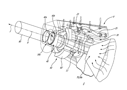
system fluidly connected to the inlet of the air conduit and operable to draw
an airflow
from the inlet and inside the air conduit.
[0004] In accordance with another general aspect, there is provided an engine
assembly, comprising: a turbo-compounded engine including a rotary internal
combustion engine having an housing and an engine shaft, the intermittent
internal
1
CA 3055846 2019-09-17
combustion engine including a coolant circuitry for circulating a liquid
coolant, the
coolant circuitry in heat exchange relationship with the housing, and a
turbine having a
turbine shaft, the turbine having an inlet fluidly connected to an exhaust of
the
intermittent internal combustion engine, the turbine shaft in driving
engagement with the
engine shaft; a porous surface configured for defining a portion of an
external surface of
an aircraft, apertures defined through the porous surface, the housing of the
internal
combustion engine in heat exchange relationship with the porous surface for
heating
the porous surface; an air conduit having an inlet fluidly connected to a
boundary layer
region outside the engine assembly via the apertures of the porous surface,
the air
conduit in heat exchange relationship with the coolant circuitry; a forced air
system
fluidly connected to the inlet of the air conduit and operable to draw an
airflow from the
inlet and inside the air conduit.
[0005] In accordance with a further general aspect, there is provided a method
of
operating an engine assembly comprising: heating a portion of an external
surface of an
aircraft being porous with heat generated by an internal combustion engine;
drawing an
airflow from a boundary layer region located over the portion of the external
surface to
an air conduit; and heating the airflow while circulating the airflow in the
air conduit by
cooling a liquid coolant being in heat exchange relationship with a housing of
the
internal combustion engine.
DESCRIPTION OF THE DRAWINGS
[0006] Reference is now made to the accompanying figures in which:
[0007] Fig. 1 is a schematic cross-sectional view of an engine assembly in
accordance
with a particular embodiment;
[0008] Fig. 2 is a schematic cross-sectional view of a possible implementation
of the
engine assembly of Fig. 1;
[0009] Fig. 3 is a schematic top view a wing defining a porous surface of the
engine
assembly of Fig. 1; and
2
CA 3055846 2019-09-17
[0010] Fig. 4 is a schematic cross-sectional view along line 4-4 of Fig. 3.
DETAILED DESCRIPTION
[0011] Referring to Fig. 1, an engine assembly 10 is generally shown and
includes an
internal combustion engine 12, which may be any type of intermittent internal
combustion engine. In a particular embodiment, the internal combustion engine
12
comprises one or more rotary units each configured for example as a Wankel
engine, or
one or more reciprocating pistons. The internal combustion engine 12 drives an
engine
shaft 14 that is used for driving a rotatable load 16. It is understood that
the engine
assembly 10 may alternately be configured to drive any other appropriate type
of load,
including, but not limited to, one or more generator(s), propeller(s),
accessory(ies), rotor
mast(s), compressor(s), or any other appropriate type of load or combination
thereof.
[0012] The internal combustion engine 12 may be a liquid cooled internal
combustion
engine in which a liquid coolant is used to extract heat generated by
combustion of a
mixture of fuel and air within at least one combustion chamber of the engine.
It is
understood that, in a liquid cooled internal combustion engine, the at least
one
combustion chamber is fluidly disconnected from an environment outside of the
at least
one combustion chamber at least during the combustion of the mixture; the at
least one
combustion chamber opening to the environment after said combustion to expel
the
exhaust gases generated therein. Consequently, in such engines, as the
combustion
occurs in an enclosed space (i.e., the at least one combustion chamber being
fluidly
disconnected from the environment), the engine accumulates a lot of heat that
needs to
be dissipated via the liquid coolant.
[0013] In a particular embodiment, the engine assembly 10 is a compound cycle
engine
system or compound cycle engine such as described in Lents et al.'s US patent
No.
7,753,036 issued July 13, 2010 or as described in Julien et al.'s US patent
No.
7,775,044 issued August 17, 2010, or as described in Thomassin et al.'s U.S.
patent
publication No. 2015/0275749 published October 1, 2015, or as described in
Bolduc et
al.'s U.S. patent publication No. 2015/0275756 published October 1, 2015, the
entire
contents of all of which are incorporated by reference herein. The engine
assembly 10
3
CA 3055846 2019-09-17
may be used as a prime mover engine, such as on an aircraft or other vehicle,
or in any
other suitable application.
[0014] In a particular embodiment, the internal combustion engine 12 is a
rotary engine
comprising three rotary units each configured as a Wankel engine, with a rotor
cavity
having a profile defining two lobes, preferably an epitrochoid, in which a
rotor is
received with the geometrical axis of the rotor being offset from and parallel
to the axis
of the rotor cavity, and with the rotor having three circumferentially-spaced
apex
portions and a generally triangular profile with outwardly arched sides, so as
to define
three rotating combustion chambers with variable volume. Alternatively, the
internal
combustion engine 12 may be any type of intermittent internal combustion
engine such
as a piston engine.
[0015] In the embodiment shown, the engine assembly 10 is an auxiliary power
unit
(APU) and the engine shaft 14 is in driving engagement with a generator. As
shown, the
engine shaft 14 is directly engaged to the generator. Alternatively, the
engine shaft 14
may be drivingly engaged to the generator via a gearbox 18 of the engine
assembly 10.
[0016] The internal combustion engine 12 has an housing 12a that defines the
combustion chambers. The housing 12a usually gets hot because of explosions of
a
mixture of air and fuel in the combustion chambers. Therefore, the housing 12a
is
cooled.
[0017] In the embodiment shown, a coolant circuitry 20 is used for circulating
a liquid
coolant, which may be any suitable liquid coolant such as oil and propylene
glycol. The
coolant circuitry 20 is in heat exchange relationship with the housing. As
illustrated on
Fig. 1, the coolant circuitry 20 includes a conduit 20a that circulates the
liquid coolant in
an out of the housing 12a and a coolant flow path 12b defined within the
housing 12a
and that is fluidly connected to the conduit 20a. The liquid coolant picks up
heat from
the housing 12a while it circulates within the coolant flow path 12b of the
housing 12a
and heat is expelled from the liquid coolant via a portion 20b of the conduit
20a that is in
heat exchange relationship with another medium of lower temperature than that
of the
liquid coolant exiting the housing of the internal combustion engine 12.
4
CA 3055846 2019-09-17
[0018] It is understood that the coolant circuitry may be used to extract heat
from any
kind of heat sources, such as, the engine 12, batteries, generators, electric
motors,
aircraft systems and accessories, either in combination or individually.
[0019] In the embodiment shown, the internal combustion engine 12 is a
component of
a turbo-compounded engine 100 of the engine assembly 10; the turbo-compounded
engine 100 including a compressor 22 for compressing the air before it is fed
to an air
inlet 12c of the internal combustion engine 12. As illustrated, the compressor
22 has an
inlet 22a fluidly connected to an environment E outside of the engine assembly
10 and
an outlet 22b fluidly connected via a conduit 24a to the inlet 12c of the
internal
combustion engine 12 for feeding compressed air to the internal combustion
engine 12.
[0020] As illustrated, the turbo-compounded engine 100 includes a turbine 26
receiving
the exhaust gases from the internal combustion engine 12. The turbine 26 has
an inlet
26a fluidly connected via a conduit 24b to an exhaust 12d of the internal
combustion
engine 12. The turbine 26 has an outlet 26b fluidly connected to the
environment E for
expelling exhaust gases generated by the internal combustion engine 12 and
after their
passage in the turbine 26.
[0021] In the case of a rotary engine, the internal combustion engine 12
provides an
exhaust flow of high pressure hot gas exiting at high peak velocity, in the
form of
exhaust pulses. The turbine 26 may comprise a single turbine, or two or more
turbine
stages in serial fluid communication; the two or more turbine stages may have
different
reaction ratios from one another and might be configured to cater to the
exhaust pulses
of the internal combustion engine 12. Other configurations are contemplated.
[0022] It is understood that variations are possible, and that, for example,
the
compressor 22 and/or turbine 26 may be omitted without departing from the
scope of
the present disclosure.
[0023] In the illustrated embodiment, the compressor 22 and the turbine 26 are
in a
driving engagement with the gearbox 18. In the illustrated embodiment, the
compressor
22 and turbine 26 rotors are engaged to a same turbine shaft 26c, which is
drivingly
CA 3055846 2019-09-17
engaged to the engine shaft 14 through the gearbox 18; the turbine shaft 26c
and the
engine shaft 14 are parallel and radially offset from one another. Alternate
configurations are possible, including, but not limited to, the rotor(s) of
the compressor
22 being engaged to a shaft separate from the turbine shaft 26c (whether
coaxial with
the turbine shaft 26c, with the engine shaft 14, or offset from both) and in
driving
engagement with the turbine shaft 26c and/or the engine shaft 14, for example
through
the gearbox 18; and/or two or more of the shafts extending at an angle
(perpendicularly
or otherwise) to each other. In the embodiment shown, the engine assembly 10
includes a load compressor 23 (Fig. 2) configured for supplying compressed air
to a
cabin of the aircraft via a conduit 25. The load compressor 23 has a
compressor shaft
that may be in driving engagement with the turbine shaft 26c either directly
or via the
gearbox 18.
[0024] In the depicted embodiment, energy from the exhaust gases exiting the
internal
combustion engine 18 is extracted by the turbine 26; the energy extracted by
the
turbine 26 being compounded with the internal combustion engine 12 to drive
the
engine shaft 14 via the gearbox 18.
[0025] In the depicted embodiment, the engine assembly 10 includes an air
conduit 30
that has an inlet 30a fluidly connected to the environment E outside the
engine
assembly 10. The air conduit 30 is in heat exchange relationship with the
coolant
circuitry 20. As illustrated, the portion 20b of the conduit 20a of the
coolant circuitry 20
is located within the air conduit 30 such that an airflow F circulating
therein will contact
the conduit 20a and be able to pick up heat from the conduit 20a via
convection
between the conduit 20a and the airflow F.
[0026] In the depicted embodiment, the engine assembly 10 further includes a
forced
air system 40 fluidly connected to the inlet 30a of the air conduit 30 and
operable to
draw the airflow F from the inlet 30a and inside the air conduit. The forced
air system 40
may be a blower (e.g., a fan within a fan casing) or a scoop configured for
creating a
pressure differential between the air conduit 30 and the environment E to draw
air
through the inlet 30a of the air conduit 30. The forced air system 40 may be
electronically, hydraulically, pneumatically, or mechanically driven. In a
particular
6
CA 3055846 2019-09-17
embodiment, the forced air system 40 is in driving engagement with the engine
shaft 14
of the internal combustion engine 12, either directly or via the gearbox 18
and/or other
transmission means.
[0027] However, it has been observed that simply drawing air from the
environment E
in the air conduit 30 creates a cooling drag. The cooling drag impairs
performance of an
aircraft containing the engine assembly 10. Therefore, it might be
advantageous to
draw the air from a boundary layer region B of a portion of an external
surface S of the
aircraft. More specifically, a boundary layer is created when the aircraft
moves with
respect to surrounding air. For a surface, the boundary layer is usually
laminar at the
beginning of the surface and develops to become turbulent as it moves away
from the
beginning of the surface. The drag created by a turbulent boundary layer is
greater than
a drag created by a laminar boundary layer. The boundary layer has a height
taken in a
direction normal to the surface S that increases from the beginning of the
surface S.
Typically, the height of a turbulent boundary layer is greater than that of a
laminar
boundary layer. The greater is the height of the boundary layer, the greater
is the drag.
Therefore, it might be possible to suck air from the boundary layer region B
to reduce
the height of the boundary layer.
[0028] Systems for boundary layer suction already exist, but their operation
does not
necessarily result in an improved performance of the aircraft. Indeed, energy
must be
provided to draw the air of the boundary layer region B. Consequently, the
added cost
resulting from the suction of the boundary layer is not necessarily
compensated by the
drag reduction resulting from said suction.
[0029] In the present case, the housing 12a of the internal combustion engine
12
requires a lot of air for cooling. The rationale is as follows: as long as a
significant
amount of air must be drawn to cool the internal combustion engine 12, it
might be
advantageous to draw the required cooling air from the boundary layer region B
developing over the portion of the external surface S of the aircraft.
[0030] Typically, an APU is a gas turbine engine that, first, does not require
as much
cooling as an intermittent internal combustion engine of equal power, and,
second, has
7
CA 3055846 2019-09-17
an efficiency being less than that of gas turbine engines used for propelling
the aircraft.
Consequently, gas turbine engine APUs are not typically used when the aircraft
is
flying. Therefore, the compressed air for pressurizing a cabin of the aircraft
and power
required for operating the different systems of the aircraft comes from the
gas turbine
engines that propel the aircraft.
[0031] Having the internal combustion engine 12 being an intermittent internal
combustion engine (e.g., rotary engine), with or without turbo-compounding,
might allow
using said APU when the aircraft is flying at least because its efficiency
might be the
same, or better, than that of the gas turbine engines that propel the
aircraft. This is
especially the case when the main engines are throttled back for descent,
approach
and landing. Furthermore, in climb, where propelling engines of the aircraft
are highly
pushed to high power/thrust, using the APU with near efficiency might allow to
generate
the required electrical power of the aircraft and compressed air for the cabin
pressurization solely with the APU instead of with, or in combination with,
the propelling
engines. This might allow a reduction of the temperature inside the propelling
engines
compared to a configuration without the disclosed engine assembly 10. This
might
extend life span of the propelling engines and/or might allow using smaller
propelling
engines than an aircraft not equipped with the disclosed engine assembly 10.
Moreover, the added cost of operating the APU might be compensated by the
reduction
in drag resulting from the suction of the boundary layer. This might not be
possible with
a conventional gas turbine engine APU because the amount of air required for
its
cooling might not be sufficient to create a drag reduction by boundary layer
suction.
Indeed, in a particular embodiment, an intermittent internal combustion
engine, such as
the turbo-compounded engine 100 shown in Fig. 1, might have from about 15 to
25
more heat to dissipate than a conventional gas turbine engine APU of equal
power.
Stated otherwise, the amount of air required for cooling a conventional gas
turbine
engine APU may not be sufficient to impart a drag reduction that would
compensate for
the cooling drag. Furthermore, a conventional gas turbine engine APU might not
be
efficient enough to be used extensively in flight. Conventional gas turbine
engine APUs
might not be able to provide enough power at high altitude to provide
pressurized air to
the aircraft while unloading the propelling engines in climb at, or descent
from, high
8
CA 3055846 2019-09-17
altitude. Moreover, a conventional gas turbine engine APU dissipate almost all
of its
heat in the exhaust gases it expels and, thus, there might not enough heat to
dissipate
to warrant an effective boundary layer suction.
[0032] Still referring to Fig. 1, the engine assembly 10 further includes a
porous surface
50 that is configured for defining the portion of the external surface S of
the aircraft. A
plurality of apertures 50a are defined through the porous surface 50.
Different
embodiments are described herein below with reference to Figs. 2-4. The inlet
30a of
the air conduit 30 is fluidly connected to the environment E via the apertures
50a of the
porous surface 50. In operation, the forced air system 40 induces the airflow
F through
the apertures 50a of the porous surface 50 following arrow Al and in the air
conduit 30
thereby suctioning the boundary layer. This might result in a reduction of the
height of
the boundary layer over the portion of the external surface S of the aircraft
compared to
a configuration in which the boundary layer is not suctioned.
[0033] As illustrated, the housing 12a of the internal combustion engine 12 is
in heat
exchange relationship with the porous surface 50. Different embodiments
providing
such a heat exchange relationship between the housing 12a of the internal
combustion
engine 12 and the porous surface 50 are described below with respect to Figs.
2-4.
Heating the porous surface 50 might be advantageous because it might increase
a
temperature of the air that enters the air conduit 30 via the apertures 50a of
the porous
surface 50. In a particular embodiment, heating the porous surface 50 allows
for de-
icing the portion of the external surface S (e.g., wings) of the aircraft
and/or to prevent
ice from accumulating on said surface. The air entering the air conduit 30 has
more
energy compared to a configuration in which the porous surface 50 is not
heated. In a
particular embodiment, increasing the energy of the air entering the air
conduit 30
increases its velocity when it is expelled from the air conduit 30 compared to
configuration in which the air entering the air conduit 30 is not heated. When
the air is
expelled in a direction corresponding to that of the movement of the aircraft,
the air
might generate a thrust that helps the gas turbine engine used for propelling
the aircraft
and that might reduce the cooling drag.
9
CA 3055846 2019-09-17
[0034] Still referring to Fig. 1, the engine assembly 10 may further include a
heat
exchanger 60. The heat exchanger 60a has at least one first conduit 60a which
may
correspond to the portion 20b of the coolant circuitry 20 and hence configured
for
circulating the liquid coolant. The heat exchanger 60 has at least one second
conduit
60b that is in heat exchange relationship with the at least one first conduit
60a. The at
least one second conduit 60b of the heat exchanger 60 is fluidly connected to
the air
conduit 30. Stated otherwise, the at least one second conduit 60a of the heat
exchanger 60 is in fluid flow communication with the environment E via the
apertures
50a of the porous surface 50 and via the air conduit 30. In a particular
embodiment, the
engine assembly 10 includes an oil circuitry; the oil circuitry may be in
fluidly flow
communication with at least one third conduit of the heat exchanger 60, the at
least one
third conduit of the heat exchanger 60 being in heat exchange relationship
with the at
least one second conduit 60b of the heat exchanger 60.
[0035] Referring now to Fig. 2, a possible implementation of the engine
assembly 10 is
illustrated. As shown, the engine assembly 10, which includes the turbo-
compounded
engine 100, is located inside an APU section V of the aircraft A (Fig. 3).
Typically, the
APU section V is located in a rear, or tail section of a fuselage of the
aircraft A. The
porous surface 50 may be a portion of an external surface of the fuselage of
the aircraft
A that separates an interior of the APU section V and the environment E
outside the
aircraft A. In the depicted embodiment, the air conduit 30 corresponds to the
interior of
the APU section V; the internal combustion engine 12 being located inside the
air
conduit 30. In the depicted embodiment, the external surface of the fuselage
of the
aircraft defines a scoop 70 that corresponds to the inlet 30a of the air
conduit 30. The
scoop 70 may be used for suctioning the boundary layer. The scoop may be a
NAGA
style scoop or any other suitable shape. A porous surface on the fuselage of
the aircraft
with no outside catcher or scoop may be used.
[0036] In the embodiment shown, the APU section V defines an outlet 30b and a
pipe
80 is fluidly connected to the outlet 30b of the APU section V. The forced air
system 40
is fluidly connected to the pipe 80. In the embodiment shown, the forced air
system 40
includes a fan 40a that is rotatable about an axis of rotation R within a fan
casing 40b.
CA 3055846 2019-09-17
The forced air system 40 is configured for directing the airflow F along a
direction
parallel to the axis R around which the fan 40a rotates.
[0037] The fan casing 40b has a cylindrical wall that defines an inlet for
receiving the
air that enters the APU section via the scoop 70. The inlet of the fan casing
are
apertures defined through the cylindrical wall of the fan casing 40b.
Therefore, the air
enters the fan casing in a substantially radial direction relative to the axis
of rotation R
of the fan 40a.
[0038] In the depicted embodiment, the heat exchanger 60 is secured to the fan
casing
40b. The at least one second conduit 60b (Fig. 1) of the heat exchanger 60 is
fluidly
connected to the inlet of the fan casing 40b. As illustrated, the heat
exchanger 60
includes three heat exchanger sections 60' circumferentially distributed
around the axis
of rotation R of the fan 40a and the inlet of the fan casing 40b includes
three apertures
defined through the cylindrical wall; each of the at least one second conduit
60b of three
heat exchanger sections 60' being fluidly connected to the outlet 30b of the
APU
section V via a respective one of the three apertures defined through the
cylindrical wall
of the fan casing 40b. The portion of the coolant circuitry 20b is in heat
exchange
relationship with each of the at least one second conduit 60b of the three
heat
exchanger sections 60'. The coolant circuitry 20 may circulate serially in
each of the
three heat exchanger sections 60', one after the other. Alternatively, the
coolant
circuitry 20 may be divided in three sub-conduits; each of the three sub-
conduits
circulating in a respective one of the three heat exchanger sections 60'.
[0039] In operation, the airflow enters the APU section V via the scoop 70,
flows
around the turbo-compounded engine 100, enters the at least one second conduit
60b
of each of the three heat exchanger sections 60' in the substantially radial
direction
relative to the rotation axis R of the fan 40a, and is expelled out of the APU
section V by
the fan 40a along an axial direction relative to the rotation axis R.
[0040] The liquid coolant enters the coolant flow path 12b of the housing 12a,
picks up
heat form the housing 12a, is directed in the heat exchanger 60 where it
transfers its
heat to the airflow F that circulate from the scoop 70 to the forced air
system 40, and is
11
CA 3055846 2019-09-17
directed back toward the housing 12a. By being heated through the heat
exchanger 60,
a thrust generated by the airflow F when expelled out of the APU section V via
the
forced air system is greater than that of a configuration in which the airflow
F is not
heated.
[0041] As shown in Fig. 2, by being located inside the air conduit 30, the
housing 12a
of the internal combustion engine 12 may transfer its heat to the portion of
the external
surface 50 of the aircraft by convection and/or conduction through a layer of
air L
between the housing 12a and said surface 50. Heat might be transferred from
the
housing 12a to the surface 50 by radiation.
[0042] Referring now to Figs. 3 and 4, alternatively or in addition, the
porous surface 50
is an external surface of a wing W of the aircraft. In the depicted
embodiment, the
porous surface 50 is located on a suction side W1 of the wing W. The portion
of the
coolant circuitry 20b extends along a span of the wing W and is in heat
exchange
relationship with the porous surface 50. The portion of the coolant circuitry
20b may be
in contact with the porous surface 50 to transfer the heat of the liquid
coolant to the
porous surface 50.
[0043] In the depicted embodiment, the portion of the coolant circuitry 20b
that is in
contact with the porous surface 50 of the wing W of the aircraft A has a first
section
20b1 and a second section 20b2. The first section 20b1 extends from a root of
the wing
W toward a remote end located adjacent a tip of the wing W and the second
section
20b2 extends from the remote end of the first section 20b1 back to the root of
the wing
W. The first and second sections 20b1, 20b2 of the portion of the coolant
circuitry 20
are offset along a chord-wise direction of the wing W; the first section 20b2
being closer
to a leading edge W2 of the wing W than the second section 20b2. In the
depicted
embodiment, an average temperature of the liquid coolant in the first section
20b2 is
greater than that in the second section 20b2. Stated otherwise, the liquid
coolant, after
exiting the coolant flow path 12b of the housing 12a of the internal
combustion engine
12 circulates in the first section 20b1 adjacent the leading edge W1 of the
wing W
before it circulates in the second section 20b2 adjacent the trailing edge W3
of the wing
W.
12
CA 3055846 2019-09-17
[0044] In the embodiment shown, the air conduit 30 is defined by a cavity C
inside the
wing W, between its pressure and suction sides and its leading and trailing
edges. The
force air system 40 includes a fan fluidly connected to the cavity C inside
the wing W
and to the environment E outside the aircraft A via the porous surface 50 and
located
adjacent the trailing edge W3 of the wing W. The forced air system 40 may
include a
plurality of fans distributed at a plurality of spanwise locations along a
span of the wing
W.
[0046] Referring to all figures, for operating the engine assembly 10 the
portion of the
external surface of the aircraft A being porous is heated with heat generated
by the
internal combustion engine 12. The airflow F is drawn from the boundary layer
region B
located over the portion of the external surface to the air conduit 30. The
airflow F is
heated while circulating in the air conduit 30 by cooling a liquid coolant
being in heat
exchange relationship with the housing 12a of the internal combustion engine
12. In the
embodiment shown, drawing the airflow F includes operating a fan 40a fluidly
connected to the air conduit 30.
[0046] Referring more particularly to Fig. 2, the internal combustion engine
12 is in the
air conduit 30, heating the portion of the external surface S includes heating
the layer of
air L located between the housing 12a and the porous surface 50 by the housing
12a.
[0047] Referring more particularly to Figs. 3-4, heating the portion of the
external
surface S includes transferring heat from the liquid coolant to the portion of
the external
surface via the contact between the conduit 20a circulating the liquid coolant
and the
portion of the external surface S.
[0048] Referring more particularly to Figs. 1-2, heating the airflow F
includes circulating
the liquid coolant in the at least one first conduit 60a of the heat exchanger
60 and
circulating the airflow F in the at least one second conduit 60b of the heat
exchanger
60.
[0049] In a particular embodiment, the disclosed engine assembly 10 allows
using an
APU of the intermittent internal combustion engine type while the aircraft is
flying. This
13
CA 3055846 2019-09-17
might allow all the power generated by the gas turbine engines of the aircraft
for
propulsion instead of using a portion of the generated power for pressurizing
the cabin
and operating the different systems of the aircraft. This might cause a
reduction in fuel
consumption of the aircraft because the disclosed turbo-compounded engine
might be
more efficient than the gas turbine engines used for propelling the aircraft.
[0050] The above description is meant to be exemplary only, and one skilled in
the art
will recognize that changes may be made to the embodiments described without
departing from the scope of the invention disclosed. Still other modifications
which fall
within the scope of the present invention will be apparent to those skilled in
the art, in
light of a review of this disclosure, and such modifications are intended to
fall within the
appended claims.
14
CA 3055846 2019-09-17