Note: Descriptions are shown in the official language in which they were submitted.
SMOKE EVACUATION ELECTROSURGICAL PENCIL WITH ADJUSTABLE
ELECTRODE AND VENT TUBE
BACKGROUND
1. Technical Field
[0001] The present disclosure relates to surgical devices. More
specifically, the
present disclosure relates to handheld smoke evacuation electrosurgical
pencils having a
telescopic nozzle movable within and relative to a handpiece and a telescopic
electrode
movable within and relative to the nozzle.
2. Background of Related Art
[0002] Electrosurgical (ES) pencils are used in surgery, typically for
cutting tissue
and/or for coagulating blood vessels. An ES pencil usually includes a
handpiece into which
electrodes of various shapes and sizes may be placed. The electrode is
supplied with a high
frequency, typically radio frequency (RF) alternating current provided by an
ES generator,
such as Medtronic's ValleylabTM LS10 or FT10 Generators. The ES generator may
supply
various waveforms suitable for achieving various surgical effects, such as
cutting,
coagulating, blend, spray, fulgurate, and the like.
[0003] While using an ES pencil, smoke is often generated. An effective
way to
evacuate surgical smoke is to use an ES pencil with an integrated smoke
evacuation nozzle in
conjunction with a suction device and an ultra-low penetration air (ULPA)
filter.
Conventional ES pencils rely on smoke evacuation shrouds attached to the ES
pencil, which
suction the smoke away via a suction device. Smoke shrouds are available
either as an
integrated part of the ES pencil or as a separate shroud attached to the ES
pencil. A smoke
nozzle, situated near the pencil's electrode, draws the smoke plume into and
through the
1
CA 3056081 2019-09-20
, a
. ,
pencil's body, through a long flexible hose, and finally into a powered
suction device outside
of the surgical field.
[0004] During a surgical procedure it is often desirable to change
the length of the
electrode. Therefore electrodes come in different lengths. However, this
results in added
expense due to inclusion of multiple electrodes in surgical kits and added
surgical time
because the surgical procedure needs to be stopped while the electrode is
being changed.
SUMMARY
[0005] The present disclosure provides an electrosurgical (ES)
pencil having an
integrated, telescopic smoke nozzle disposed within a handle housing. The ES
pencil
includes an electrical plug configured to couple to an electrosurgical
generator. The handle
housing may have an ergonomic shape and have a slim cross-sectional area
(e.g., having a
height, width, or diameter of from about 10 mm to about 20 mm). The nozzle
evacuates
surgical smoke through the handle housing and through smoke evacuation tubing
into a
smoke evacuator. The smoke evacuation tubing may be corrugated to minimize
kinking and
to allow for free and natural movement of the ES pencil. The nozzle may be
clear to aid with
visualization of an electrode and its electrode tip. The nozzle also directs
the smoke past a
printed circuit board (PCB) coupled to a rocker switch to limit alternative
current paths that
could potentially harm the user due to smoke intrusion into sensitive
electronic components.
The PCB has an over mold on the front and back of the pencil as well as tape
that covers the
PCB to limit moisture ingress. A rocker switch is disposed over the PCB and is
used to
control the energy delivered by the ES pencil by engaging the pushbutton
switches disposed
on the PCB.
[0006] The extension and retraction force of the nozzle may be
controlled by a
friction pad that contacts the nozzle. The friction pad may be located within
a distal portion
2
CA 3056081 2019-09-20
, .
of the handle housing, such that the friction pad contacts the nozzle. The ES
pencil also
includes a high flow swivel connector disposed at a proximal portion of the
handle housing.
The swivel connector allows the ES pencil and the tubing to rotate
independently from each
other. The swivel connector allows the tubing to rest in a comfortable
position and minimizes
the overall weight of the pencil by increasing the amount of tubing that may
rest on surgical
drapes.
[0007] The ES pencil also includes a conductive tube connected to
a wire, which is in
turn connected to the plug through the PCB, such that the conductive tube
conducts
electrosurgical current to an electrode from the generator. The electrode and
the conductive
tube have a non-conductive shrink-wrap or coating that prevents alternative
contact sites
during surgery. The conductive tube may be secured within the nozzle while the
electrode is
configured to move within the conductive tube by using an electrode clip that
is configured to
frictionally slide within the conductive tube.
[0008] The present disclosure includes multiple embodiments, each
of which includes
multiple aspects. Various aspects of the embodiments are interchangeable among
the
disclosed embodiments. According to one embodiment of the present disclosure,
an
electrosurgical smoke evacuation pencil is disclosed, which includes: a handle
housing
having a proximal end portion and a distal end portion, the handle housing
defining a first
lumen therethrough. The ES pencil also includes a nozzle disposed within the
first lumen and
defining a second lumen, the nozzle being movable relative to and within the
handle housing
and extending proximally past the proximal end portion of the handle housing.
The ES pencil
further includes a swivel connector coupled to the distal end portion of the
handle housing,
the swivel connector is configured to couple to a suction source. The ES
pencil also includes
a hub assembly securedly disposed within the second lumen, the hub assembly
includes a
3
CA 3056081 2019-09-20
,
, .
conductive tube configured to couple to a source of electrosurgical energy,
and an electrode
slidably disposed within the conductive tube, the electrode being movable
relative to and
within the conductive tube.
100091 According to one aspect of the above embodiment, the ES
pencil includes an
electrode clip slidably disposed within the conductive tube, the electrode
clip being movable
relative to and within the conductive tube, where the electrode is removably
coupled to the
electrode clip.
[0010] According to another aspect of the above embodiment, the ES
pencil further
includes a proximal support disposed over a proximal end portion of the
conductive tube and
a distal support disposed over a distal end portion of the conductive tube.
The proximal
support and the distal support may be formed from a dielectric material. The
hub assembly
may further include a dielectric material disposed over the conductive tube.
The dielectric
material may be a heat-shrinkable wrap. Each of the proximal support and the
distal support
may include a pair of flanges configured to secure each of the proximal
support and the distal
support within the nozzle. The conductive tube may include a proximal stop
member and
longitudinal movement of the electrode clip is limited by the distal support
and the proximal
stop member.
[0011] According to a further aspect of the above embodiment, the
electrode clip may
also include a socket configured to receive a proximal end portion of the
electrode and a pair
of contact wings configured to contact an inner surface of the conductive
tube. The electrode
clip may include a plurality of prongs disposed at a proximal portion of the
electrode clip and
a plurality of surface features disposed at a distal portion of the electrode
clip, the surface
features being configured to contact an inner surface of the conductive tube.
4
CA 3056081 2019-09-20
[0012] According to one aspect of the above embodiment, the ES pencil may
further
include a midframe disposed within the handle housing and over the nozzle. The
midframe
may include a pair of wings configured to frictionally engage the nozzle. The
handle housing
includes an upper portion having a switch opening and a lower portion. The ES
pencil also
includes a circuit board including at least one switch and a rocker disposed
through the
switch opening, the rocker configured to engage the at least one switch.
[0013] According to another aspect of the above embodiment, the distal
end portion
of the handle housing includes a tubular connector. The swivel connector
includes a distal
joint coupled to the tubular connector and rotatable about a first
longitudinal axis defined by
the tubular connector. The swivel connector also includes an intermediate
joint coupled to the
distal joint and pivotable about an axis that is perpendicular to the first
longitudinal axis. The
swivel connector further includes a proximal joint coupled to the intermediate
joint and
rotatable about a second longitudinal axis defined by the intermediate joint.
The distal joint
may include a pair of opposing pins and the intermediate joint may include a
pair of opposing
openings configured to engage the pair of opposing pins. The distal joint also
includes an
outer curved surface and the intermediate joint includes an inner curved
surface, the outer
curved surface includes a raised surface configured to limit pivoting movement
of the
intermediate joint.
[0014] According to one embodiment of the present disclosure, an
electrosurgical
smoke evacuation pencil is disclosed, which includes a handle housing having a
proximal end
portion and a distal end portion, the handle housing defining a first lumen
therethrough. The
ES pencil includes a nozzle disposed within the first lumen and defining a
second lumen, the
nozzle being movable relative to and within the handle housing and extending
proximally
past the proximal end portion of the handle housing. The ES pencil also
includes a swivel
CA 3056081 2019-09-20
. ,
connector coupled to the distal end portion of the handle housing, the swivel
connector is
configured to couple to a suction source. The ES pencil further includes a hub
assembly
securedly disposed within the second lumen, the hub assembly including a
conductive tube
configured to couple to a source of electrosurgical energy. The ES pencil also
includes an
electrode clip slidably disposed within the conductive tube, the electrode
clip being movable
relative to and within the conductive tube, and an electrode removably coupled
to the
electrode clip.
BRIEF DESCRIPTION OF THE DRAWINGS
[0015] Embodiments of the present disclosure are described herein with
reference to
the accompanying drawings, wherein:
[0016] FIG. 1 is a perspective view of a smoke evacuation
electrosurgical (ES) pencil
according to one embodiment of the present disclosure;
[0017] FIG. 2 is a perspective view of the ES pencil of FIG. 1 with a
nozzle extender
attachment according to the present disclosure;
[0018] FIG. 3 is a perspective view of a smoke evacuation ES pencil
according to
another embodiment of the present disclosure;
[0019] FIG. 4 is a perspective, cross-sectional view of the ES pencil of
FIG. 3;
[0020] FIG. 5 is a perspective view of the ES pencils of FIGS. 1 and 3,
with parts
separated;
[0021] FIG. 6 is a perspective view of an upper portion of a handle
housing of the ES
pencils of FIGS. 1 and 3;
6
CA 3056081 2019-09-20
, . [0022] FIG. 7 is an interior view of the upper portion of the
handle housing of FIG. 6;
[0023] FIG. 8 is a perspective view of a lower portion of a handle housing
of the ES
pencils of FIGS. 1 and 3;
[0024] FIG. 9 is a perspective view of a swivel connector of the ES pencils
of FIGS. 1
and 3 with parts separated, according to the present disclosure;
[0025] FIG. 10 is a side, cross-sectional view of the swivel connector of
FIG. 9;
[0026] FIG. 11 is a perspective view of a midframe disposed within the
handle
housing of the ES pencils of FIGS. 1 and 3 according to the present
disclosure;
[0027] FIG. 12 is a perspective view of a circuit board disposed on the
midframe of
the ES pencils of FIGS. 1 and 3 according to the present disclosure;
[0028] FIG. 13 is a perspective view of a nozzle of the ES pencils of FIGS.
1 and 3
according to the present disclosure;
[0029] FIG. 14 is a perspective view of a hub assembly separated from the
nozzle of
the ES pencils of FIGS. 1 and 3 according to the present disclosure;
[0030] FIG. 15A is a perspective view of the hub assembly of the ES pencils
of FIGS.
1 and 3 with parts separated;
[0031] FIG. 15B is a perspective view of the proximal end portion of the
hub
assembly of FIG 15A;
[0032] FIG. 16 is a perspective view of an electrode clip for coupling to
an electrode
of the ES pencils of FIGS. 1 and 3 according to the present disclosure;
7
CA 3056081 2019-09-20
. .
[0033] FIG. 17 is a perspective view of a conductive tube of the hub
assembly of the
ES pencils of FIGS. 1 and 3 according to the present disclosure;
[0034] FIG. 18 is a perspective view of an electrode clip according to
another
embodiment of the present disclosure for coupling to the electrode of the ES
pencils of FIGS.
1 and 3;
[0035] FIG. 19 is a perspective view of a hub assembly according to
another
embodiment of the present disclosure for coupling to the electrode of the ES
pencils of FIGS.
1 and 3;
[0036] FIG. 20 is a perspective view of a smoke evacuation ES pencil
according to a
further embodiment of the present disclosure;
[0037] FIG. 21 is a perspective, cross-sectional view of the ES pencil
of FIG. 20;
[0038] FIG. 22 is a side view of a swivel connector according to another
embodiment
of the present disclosure;
[0039] FIG. 23 is a perspective view of a smoke evacuation ES pencil
according to an
embodiment of the present disclosure; and
[0040] FIG. 24 is a perspective, cross-sectional view of the ES pencil
of FIG. 23.
DETAILED DESCRIPTION OF EMBODIMENTS
[0041] Embodiments of the present disclosure are now described in detail
with
reference to the drawings in which like reference numerals designate identical
or
corresponding elements in each of the drawings. The embodiments may be
combined in any
manner consistent with the functionality of the apparatus and/or method
disclosed herein. As
8
CA 3056081 2019-09-20
used herein, the term "clinician" refers to a doctor, a nurse or any other
care provider and
may include support personnel. Throughout this description, the term
"proximal" will refer
to the portion of the device or component thereof that is closer to the
clinician and the term
"distal" will refer to the portion of the device or component thereof that is
farther from the
clinician. The terms "substantially equal to" or "substantially the same"
denote that two
values are within 5% of each other. Additionally, in the drawings and in the
description that
follows, terms such as front, rear, upper, lower, top, bottom, and similar
directional terms are
used simply for convenience of description and are not intended to limit the
disclosure. In
the following description, well-known functions or constructions are not
described in detail to
avoid obscuring the present disclosure in unnecessary detail.
[0042] The present disclosure describes multiple embodiments of smoke
evacuation
electrosurgical (ES) pencils, each of which includes a handle with an
integrated smoke
nozzle. In embodiments, the nozzle may be telescopic, such that the nozzle is
movable
relative to and within the handle. Each of the ES pencils also includes an
electrode
electrically coupled to a conductive tube disposed within the nozzle. The
conductive tube
may be secured to the nozzle and in certain embodiments, the electrode may
also be
telescopic, such that the electrode is movable relative to and within the
conductive tube, and
by extension, the nozzle, while maintaining electrical contact with the
conductive tube. The
ES pencil may also include a swivel connector coupled to a proximal end of the
handle. The
swivel connector may include a ball joint, a pivot joint, or combinations
thereof The swivel
connector couples the nozzle to a flexible tube, which is in turn connected to
a smoke
evacuator.
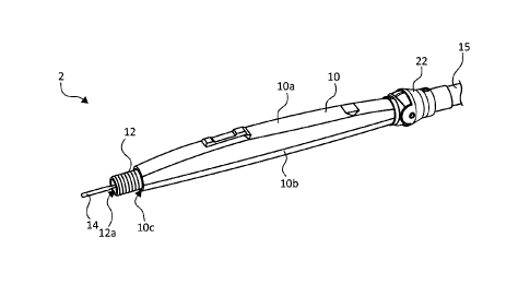
[0043] With reference to FIG. 1, a non-telescopic ES pencil 2 is
disclosed, which
includes a handle housing 10 formed from a thermoplastic material. The handle
housing 10
9
CA 3056081 2019-09-20
. . , .
includes an upper portion 10a and a lower portion 10b, which are secured to
each other using
any suitable methods, e.g., ultrasonically welded, to secure internal
components of the ES
pencil 2. The handle housing 10 defines a lumen 10c therethrough. The ES
pencil 2 also
includes a nozzle 12 that is securely coupled within the housing 10, and an
electrode 14
disposed within the nozzle 12. The nozzle 12 also defines a lumen 12a, which
is in fluid
communication with the lumen 10c.
[0044] The nozzle 12 is formed from a dielectric material, such as
polyimide, and
provides for the suctioning of gaseous byproducts through the handle housing
10. In
embodiments, dielectric material of the nozzle 12 may be a transparent,
substantially
transparent or translucent material configured to facilitate visual acuity in
the surgical field.
However, it will be clear that an opaque or substantially opaque material may
also be used as
such materials would not affect the operation of the device. The ES pencil 2
also includes a
swivel connector 22 coupling the nozzle 12 to a tubing 15. As shown in FIG. 2
the nozzle 12
may also include a distal end portion 12b, which is configured to couple to a
nozzle extender
attachment 13. The distal end portion 12b may have a plurality of ribs 12c for
frictionally
engaging the nozzle extender attachment 13. This allows the ES pencil 2 to
have a longer
nozzle 12 to use with a longer electrode 14 for deeper access.
[0045] With reference to FIGS. 3-5, a telescopic ES pencil 4
includes the same
components as the ES pencil 2 and is different with respect to its
functionality. The ES
pencil 4 also includes the housing 10. The ES pencil 4 includes the nozzle 12
that is
movable relative to the handle housing 10 and within the lumen 10c. As shown
in FIGS. 3
and 4, both the nozzle 12 and the electrode 14 are extended longitudinally.
The nozzle 12
also includes the taper portion 12b. The electrode 14 is slidably coupled
within the nozzle 12
such that the electrode 14 is movable relative to the nozzle 12. The electrode
14 includes a
CA 3056081 2019-09-20
proximal portion 14a, an insulative coating 14b, and a distal portion 14c
having a treatment
portion e.g., a blade (as shown), a hook, a needle, etc. (FIG. 5) It is
envisioned that other
variants of ES pencils 2 and 4 may include either the nozzle 12 or the
electrode 14 that are
telescopic with the other being stationary, namely, the nozzle 12 is secured
to the housing
while the electrode 14 is movable and vice versa.
[0046] With reference to FIGS. 5-7, the upper portion 10a includes a
switch opening
16 that accommodates a rocker switch 18 (FIG. 5). Rocker switch 18 may be
replaced by any
of suitable actuation mechanism, such as a multistage push button switch, two
or more push
button switches, a pressure sensitive transducer, or the like. The upper
portion 10a also
includes a tubular member 20 disposed at a distal end portion for coupling to
the swivel
connector 22 (FIG. 5). The tubular member 20 defines a lumen 20a, which is in
fluid
communication with the lumen 10c, allowing for the smoke evacuated from the
surgical site
to flow from the nozzle 12, through the handle housing 10, and the tubular
member 20 to the
tubing 15, namely, through the lumens 10c, 12a, and 20a. In embodiments
tubular member
20 may be included on bottom portion 10b rather than upper portion 10a.
[0047] With reference to FIG. 5, the swivel connector 22 is coupled to
the tubing 15,
which is configured to couple of a smoke evacuator (not shown). The tubing 15
may be
corrugated by including a spiral spine 15a disposed on an outer surface of the
tubing 15. The
corrugated structure of the tubing 15 minimizes kinking and allows for more
flexibility of the
tubing 15. The tubing 15 also includes an opening 15b at any point along its
length for
passage of an electrosurgical cable 17 into a lumen 15c defined within the
tubing 15. The
cable 17 is coupled to a connector plug 19 for connection to an
electrosurgical generator (not
shown).
11
CA 3056081 2019-09-20
[0048] As shown in FIG. 7, the upper portion 10a also includes a notch 24
formed on
an inner surface of the upper portion 10a, which secures the nozzle 12 within
the handle
housing 10 in the stationary variant of the ES pencils. With reference to FIG.
8, the lower
portion 10b includes a guide rail 26 disposed on an inner surface of the lower
portion 10b,
which allows the nozzle 12 to move within the handle housing 10.
[0049] With reference to FIGS. 9 and 10, the swivel connector 22 includes
a distal
joint 23, an intermediate joint 25, and a proximal joint 27. The distal joint
23 includes a distal
tubular portion 23a configured to engage the tubular member 20 of the upper
portion 10a
such that the distal joint 23 can rotate about a first longitudinal axis
defined by the tubular
connector 20. The distal joint 23 also includes a pair of pins 23b (only one
is shown) defining
a pivot axis perpendicular to the first longitudinal axis. Furthermore, the
distal joint 23
includes an outer curved surface 23c extending from a proximal edge to a
distal edge having
a raised surface 23d.
[0050] The intermediate joint 25 includes a pair of wings 25a, each of
which includes
an opening 25b configured to engage corresponding pins 23b of the distal joint
23. This
allows the intermediate joint 25 to pivot relative to the distal joint 23
about the pivot axis. In
embodiments, the openings 25b may be disposed on the distal joint 23 and the
pins 23b may
be disposed on the intermediate joint 25.
[0051] The intermediate joint 25 also includes an inner curved surface
25c which is
configured to mate with the outer curved surface 23c such that as the
intermediate joint 25
moves relative to the distal joint 23 without forming any gaps, which let
gases escape
therethrough or cause an unintended vacuum leak as shown in FIG. 10. The
raised surface
23d of the distal joint 23 limits the rotation of the intermediate joint 25 by
acting as a stop
member. While pivoting the cross section of a passage through the distal joint
23 and the
12
CA 3056081 2019-09-20
. , . ,
intermediate joint 25 is maintained because the intermediate joint 25 overlaps
the distal joint
23 as illustrated in FIG. 10. Maintaining the same cross-sectional area of the
passage allows
for a higher flow rate than other swivel joint designs.
[0052] The intermediate joint 25 also includes a tubular portion
25e configured to
engage the proximal joint 27, which is rotatably coupled to the intermediate
joint 25 allowing
the proximal joint 27 to rotate about a second longitudinal axis defined by
the intermediate
joint 25. The proximal joint 27 is also coupled to the tubing 15 at a proximal
end of the
proximal joint 27. This allows the proximal joint 27 along with the tubing 15
to rotate about
the second longitudinal axis. Thus, the swivel connector 22 provides three
degrees of
freedom, one at each of the distal joint 23 (rotation about the first
longitudinal axis), the
intermediate joint 25 (pivoting about the pivot axis perpendicular to the
first and/or the
second longitudinal axes), and proximal joint 27 (rotation about the second
longitudinal axis).
[0053] Referring to FIGS. 5 and 11, the ES pencils 2 and 4 also
include a midframe
28 that is disposed in the upper portion 10a. As shown in FIG. 5 below, the
midframe 28
includes an upper support surface 30 and a pair of tabs 32 extending upwardly
from the upper
support surface 30. The midframe 28 is disposed over the nozzle 12; as such
the smoke
evacuated from the treatment site bypasses the midframe 28 and a circuit board
34 disposed
thereon. Similarly, in the ES pencil 4, the midframe 28 is disposed over the
nozzle 12 and
outside the travel path of the nozzle 12.
[0054] Referring again to FIGS. 5 and 12, the circuit board 34 is
disposed on the
upper support surface 30 and is secured by the pair of tabs 32. The circuit
board 34 includes
a pair of pushbutton switches 36, which are aligned with the rocker 18 that is
also pivotally
secured by the pair of tabs 32 thereby allowing for activation of the
pushbutton switches 36
when the rocker 18 is pressed (FIG. 5). The circuit board 34 is coupled at its
proximal end
13
CA 3056081 2019-09-20
. .
portion 34a to the cable 17, which interconnects the circuit board 34 to the
electrosurgical
generator (not shown). The circuit board 34 is also coupled to an electrode
lead 40 at its
distal end portion 34b, which interconnects the circuit board 34 to the
electrode 14. In
embodiments, the connections to the circuit board 34 of the cable 17 and the
electrode lead
40 may be reversed, e.g., the electrode lead 40 is coupled to the proximal end
portion 34a and
the cable 17 is coupled to the distal end portion 34b, or the connections may
be coupled to the
same end.
100551 The circuit board 34 may be enclosed in a dielectric material to
prevent
alternative current paths that could potentially harm the user. In
embodiments, the circuit
board 34 and the pushbutton switches 36 may be wrapped in a heatshrinkable
material or
dielectric tape such as SURLYN ionomer resin tape from DuPont of Wilmington,
DE. The
distal and proximal end portions 38a and 38b may be encased in dielectric
material, such as
polyimide, epoxies, and the like using any suitable techniques, such as
overmolding or
casting.
100561 As shown in FIG. 11, the midframe 28 also includes a pair of
wings 42
disposed at a proximal end portion and a pair of lips 44 running along the
length of the
midframe 28. The wings 42 and lips 44 extend downward and are configured to
secure the
nozzle 12. Additionally, in telescopic ES pencil 4, the wings 42 also act as a
friction pad by
contacting the nozzle 12 and securing the nozzle 12 within the housing 10
unless sufficient
force is used to move the nozzle 12, thereby modulating the amount of force
needed to move
the nozzle 12 longitudinally. The midframe 28 also includes a cutout 43
disposed between the
wings 42 and lips 44 for routing the electrode lead 40 and another cutout 45
at the distal end
portion for routing the cable 17.
14
CA 3056081 2019-09-20
[0057] As shown in FIG. 13, the nozzle 12 has a tubular structure and
includes a
protrusion 46 disposed at a distal end portion of an outer surface. The
protrusion 46 may be
inserted into the notch 24 of the upper portion 10a (FIG. 7) to assemble the
stationary ES
pencil 2 or into the guide rail 26 of the lower portion 10b (FIG. 8) to
assembly the telescopic
ES pencil 4. This allows for manufacturing the same components, namely upper
and lower
portions 10a and 10b of the housing 10 to make different variants, namely, the
stationary ES
pencil 2 and the telescopic ES pencil 4, by simply orienting the nozzle 12
either upwardly to
engage the notch 24 or downwardly to engage the guide rail 26.
[0058] During assembly of the stationary ES pencil 2, the nozzle 12 is
oriented with
the protrusion 46 facing the inner surface of the upper portion 10a such that
the protrusion 46
is inserted into the notch 24 (FIG. 7). The notch 24 is sized to be
substantially the same as
the protrusion 46, such that the protrusion 46 is secured therein, thereby
preventing the nozzle
12 from moving within the handle housing 10, either rotationally or
longitudinally.
[0059] During assembly of the telescopic ES pencil 4, the nozzle 12 is
oriented with
the protrusion 46 facing the inner surface of the lower portion 10b such that
the protrusion 46
is disposed within the guide rail 26 (FIG. 8). Engagement of the protrusion 46
within the
guide rail 26 limits rotational movement of the nozzle 12 about a main
longitudinal axis
defined by the housing 10 and allows the nozzle 12 to move only in a
longitudinal direction
along the main longitudinal axis within the housing 10.
[0060] As shown in FIGS. 14 and 15A, the nozzle 12 also includes a hub
assembly 48
disposed therein. The hub assembly 48 provides an electromechanical interface
for the
electrode 14. The hub assembly 48 is secured within the nozzle 12 by a
proximal support 50
and a distal support 52, which are formed from a dielectric material. Each of
the proximal
support 50 and the distal support 52 includes a pair of flanges 50a and 52a,
respectively,
CA 3056081 2019-09-20
, .
. .
which secure the proximal support 50 and the distal supports 52 within the
nozzle 12. In
embodiments, the nozzle 12 may include a pair of slots 47a (FIG. 13)
configured to engage
the flanges 52a of the distal support 52. The slots 47a may be sized to
prevent longitudinal
and lateral movement of the flanges 52a. In addition, the vertical distance
between the
flanges 52a may be longer than the inner diameter of the nozzle 12, such that
the flanges 52a
fit within the slots 47a.
[0061] With reference to FIG. 15A, which shows the hub assembly 48,
the hub
assembly 48 includes a cylindrical conductive tube 54 that is inserted into a
distal opening of
the proximal support 50 and a proximal opening of the distal support 52.
Proximal support
50 may further include a plug 51 (see FIG. 15B), which may be received in a
proximal end
51b of proximal support 50 to help minimize the ingress of blood, saline,
fluids, condensation
or other moisture. The conductive tube 54 is coupled to the electrode lead 40,
such that the
conductive tube 54 conducts electrosurgical energy to the electrode 14. The
electrode lead 40
may be crimped or soldered to the conductive tube 54. The electrode lead 40
extends from
the distal end portion 34b of the circuit board 34 and is coupled to a
proximal end portion 54a
of the conductive tube 54 since the conductive tube 54 is coupled to the
electrode 14 at its
distal end portion 54b. The electrode lead 40 may exit from either a proximal
or distal end of
the conductive tube 54 and the nozzle 12 and is coupled to the circuit board
34. In
embodiments, plug 51 may include a groove 51a configured to fit around the
electrode lead
40, allowing for routing electrode lead 40 from the proximal end of conductive
tube 54 and
through proximal support 50. Alternatively, plug 51 may include an opening
therethrough
(e.g., centrally located) through which electrode lead 40 may be routed for
connecting to
circuit board 34. It may be further appreciated that the plug 51 may be
located at distal
support member 58 and route the electrode lead 40 in a similar manner from
that location.
16
CA 3056081 2019-09-20
, =
. .
[0062] Outside surface of the conductive tube 54 may be insulated
by disposing a
dielectric material 56 over the conductive tube 54. The dielectric material 56
may be any
dielectric polymer applied by dipping, casting, spraying, and other suitable
methods. In
embodiments, the dielectric material 56 may be a heat-shrink wrap. The
dielectric material 56
may be disposed over the conductive tube 54, the proximal support 50, and the
distal support
52, thereby securing these components to each other. Additionally, the
dielectric material 56
along with the proximal support 50 and distal support 52 insulate the outer
surface of the
conductive tube 54. The dielectric material 56 prevents smoke and fluid from
entering the
conductive tube 54 and causing alternative current paths during use of the ES
pencil 2 and ES
pencil 4.
[0063] The hub assembly 48 also includes an electrode clip 58 that
is slidably
disposed within the conductive tube 54 and is inserted into the distal end
portion 54b. As
shown in FIG. 16, the electrode clip 58 includes a socket 58a that receives
the proximal
portion 14a of the electrode 14 and one or more pairs of contact wings 58b and
58c, which
are configured to frictionally engage an inner surface of the conductive tube
54. The contact
wings 58b and 58c are spaced apart such that in order to be inserted into the
conductive tube
54, the contact wings 58b and 58c may be approximated together and once
inserted, the
contact wings 58b and 58c spread apart to engage the inner surface of the
conductive tube 54.
The engagement of the contact wings 58b and 58c provides for an
uninterruptable electrical
contact between the electrode clip 58 and the conductive tube 54 while
allowing for the
electrode clip 58 to slide within the conductive tube 54. In addition, the
contact wings 58b
and 58c also act as friction pads by contacting the conductive tube 54 and
securing the
electrode clip 58 within the conductive tube 54 unless sufficient force is
used to move the
electrode clip 58, by moving the electrode 14. In addition, the electrode clip
58 may also
17
CA 3056081 2019-09-20
=
rotate within the conductive tube 54, or alternatively, the electrode 14 may
rotate within the
electrode clip 58, about a longitudinal axis defined by the conductive tube
54.
[0064] With reference to FIGS. 16 and 17, the conductive tube 54 and the
electrode
clip 58 may be formed by stamping and rolling sheet metal of suitable gauges.
The
conductive tube 54 includes a pair of stamped tabs 60, which act as proximal
stops for the
electrode clip 58 and the distal support 52 acts as a distal stop, thereby
limiting the distance
that the electrode clip 58 can slide within the conductive tube 54. The tabs
60 may be
disposed anywhere along the conductive tube 54 to allow for desired travel of
the electrode
clip 58. Thus, in the stationary ES pencil 2, the tabs 60 may be disposed by a
distance
substantially equal to the length of the electrode clip 58 thereby preventing
longitudinal
movement the electrode clip 58. In the telescopic ES pencil 2, the tabs 60 may
be disposed
any distance larger than the length of the electrode clip 58 to accommodate
its travel within
the conductive tube 54.
[0065] The telescopic movement of the electrode 14 is enabled due to the
frictional
engagement of the electrode 58 with the conductive tube 54. Thus, the
frictional engagement
of the electrode clip 58 with the electrode 14 is higher than that of the
electrode clip 58 with
the conductive tube 54. The extension and retraction force required to move
the electrode
clip 58 can be controlled with the design of the electrode clip 58 such as by
adjusting the
length of the wings 58b and 58c or the spring rate of the electrode clip 58 by
controlling how
tightly the electrode clip 58 is wound. Proximal portion 14a of the electrode
14 is seated
more securely within the socket 58a of the electrode clip 58 than the
engagement of the
contact wings 58b and 58c with the conductive tube 54. Thus, when the
electrode 14 is
moved in a longitudinal direction, the electrode clip 58 slides within the
conductive tube 54.
The electrode 14 may be removed from the electrode clip 58 by pulling on the
electrode 14 in
18
CA 3056081 2019-09-20
. =
, .
a distal direction until the electrode clip 58 reaches the distal support 52,
which acts as a
distal stop, and by applying additional force to dislodge the proximal portion
14a of the
electrode 14 from the socket 58a of the electrode clip 58.
[0066] In the stationary ES pencil 2, the nozzle 12 and the
conductive tube 54, which
is secured within the nozzle 12, remain stationary within the handle housing
10. In the
telescopic variant, the nozzle 12 and the electrode 14 are movable relative to
the handle
housing 10 and each other. The nozzle 12 may be moved by pulling or pushing on
the nozzle
12. Similarly, the electrode 14 may be extended from or retracted into nozzle
12 by pulling
or pushing on the electrode 14. However, during extraction or retraction of
the electrode 14
the conductive tube 54 remains stationary within the nozzle 12.
[0067] It is contemplated that the ES pencil 2 may have a
stationary nozzle 12 but a
movable electrode 14 by using the conductive tube 54 with the tabs 60 disposed
in the
manner described above with respect to FIG. 17. It is further contemplated
that the ES pencil
4 may have a telescopic nozzle 12 but a stationary electrode 14 but using a
conductive tube
54 with the tabs 60 limiting the movement of the electrode clip 58.
[0068] With reference to FIG. 18, another embodiment of an
electrode clip 158 which
may be used with the hub assembly 48 of the ES pencil 2 or the ES pencil 4.
The electrode
clip 158 also includes a lumen 160 for receiving the electrode 14. The
electrode clip 158 also
includes a plurality of prongs 162 disposed at a distal portion of the
electrode clip 158 and a
plurality of surface features 164 disposed at a proximal portion of the
electrode clip 158. The
prongs 162 include a pointed end 162a and a curved portion 162b.
[0069] With reference to FIG. 19, another embodiment of a hub
assembly 148, which
may be used interchangeably with any of the described embodiments, such as the
electrode
clip 58 or electrode clip 158, the ES pencil 2 or the ES pencil 4. The hub
assembly 148 is
19
CA 3056081 2019-09-20
. =
. .
substantially similar to the hub assembly 48 and includes a conductive tube
154, which has a
faceted structure. In embodiments, the conductive tube 154 may have any number
of facets
154a, such as hexagonal, octagonal, etc. The electrode clip 58 or the
electrode clip 158 can
move longitudinally and rotationally within the conductive tube 154. The
facets 154a of the
conductive tube 154 allow for incremental rotation of the electrode clip 58
about a
longitudinal axis defined by the conductive tube 154 by requiring a higher
amount of torque
to rotate the electrode 14 and the electrode clip 58 or the electrode clip 158
to each corner
between the facets 154a of the conductive tube 154.
[0070] The hub assembly 148 also includes a proximal support 150
and a distal
support 152, which may be formed by overmolding the proximal support 150 and
the distal
support 152 over the conductive tube 154. In embodiments, the proximal support
50 and the
distal support 52 may be overmolded over the conductive tube 54 as well. The
distal support
152 may include an opening 153 for passage of the electrode lead 40
therethrough.
[0071] With reference to FIG. 19, as the electrode 14 is inserted
into the lumen 160 of
the electrode clip 158, the electrode clip 158 is inserted into a conductive
tube 154, and a
proximal end of the electrode 14 engages the curved portions 162b of the
prongs 162 thereby
compressing the prongs 162 and moving the pointed ends 162a to pierce an
insulative coating
14b of the electrode 14, thereby securing the electrode 14 within the
electrode clip 158. The
insulative coating 14b may be any dielectric polymer applied by dipping,
casting, spraying,
and other suitable methods. In embodiments, the insulative coating 14b may be
a heatshrink
wrap. The surface features 164 may be bumps, wings, or any other structures
configured to
engage the conductive tube 154. Similar to the contact wings 58b and 58c,
engagement of
the surface features 164 provides for an uninterruptable electrical contact
between the
CA 3056081 2019-09-20
. . = .
electrode clip 158 and the conductive tube 54 while allowing for the electrode
clip 158 to
slide within the conductive tube 154.
[0072] In addition, the surface features 164 also act as friction
pads by contacting the
conductive tube 54 and securing the electrode clip 58 within the conductive
tube 154 unless
sufficient force is used to move the electrode clip 158, by moving the
electrode 14. Since the
electrode 14 is secured to the electrode clip 158 via the prongs 162, the
electrode clip 158
may be moved within the conductive tube 54 by pulling or pushing on the
electrode 14.
[0073] With reference to FIGS. 20 and 21, another embodiment of an
ES pencil 6 is
shown and includes the telescopic nozzle 12 as described above with respect to
ES pencil 4.
In other embodiments, the ES pencil 6 may have a stationary nozzle 12. The ES
pencil 6 is
substantially similar to the ES pencils 2 and 4 and includes the same
components described
above.
[0074] With reference to FIG. 20, the swivel connector 122 includes
a distal joint 123
and a proximal joint 127. The swivel connector 122 is a ball joint with the
distal joint 123
having a tubular section 123a configured to be inserted into the tubular
member 20 of the
upper portion 10a such that the distal joint 123 can rotate about a first
longitudinal axis
defined by the distal joint 123. The distal joint 123 includes an outer curved
surface 123c
configured to engage an inner curved surface 127a of the proximal joint 127.
The proximal
joint 127 also includes a tubular section 127b configured to couple to the
tubing 15. The ball
joint design of the swivel connector 122 allows the proximal joint 127 to
rotate and pivot
relative to the distal joint 123 in two planes at the same time.
[0075] With reference to FIGS. 23 and 24, a further embodiment of
an ES pencil 8 is
shown. The ES pencil 8 is substantially similar to the ES pencil 2, 4, and 6
in that the nozzle
12 and the electrode 14 may be stationary or movable as described above. The
ES pencil 8
21
CA 3056081 2019-09-20
. . . .
includes a friction pad 142 disposed in the upper portion 10a of the handle
housing 10. The
friction pad 142 may be formed from an elastomeric, conformable material such
as silicone
rubber. Suitable silicone rubbers include room
temperature vulcanization
(RTV) silicone rubbers; high temperature vulcanization (HTV) silicone rubbers
and low
temperature vulcanization (LTV) silicone rubbers. These rubbers are known and
readily
available commercially such as SILASTIC 735 black RTV and SILASTIC114. 732
RTV,
both from Dow Corning; and 106 RTV Silicone Rubber and 90 RTV Silicone Rubber,
both
from General Electric. Other suitable silicone materials include the silanes,
siloxanes (e.g.,
polydimethylsiloxanes) such as, fluorosilicones, dimethylsilicones, liquid
silicone rubbers
such as vinyl crosslinked heat curable rubbers or silanol room temperature
crosslinked
materials, and the like.
[0076] The friction pad 142 may be secured or simply placed within
the upper portion
10a to allow for the friction pad 142 to contact the nozzle 12 by resting on
the nozzle 12. The
friction pad 142 contacts and secures the nozzle 12 within the housing 10
unless sufficient
force is used to move the nozzle 12, thereby modulating the amount of force
needed to move
the nozzle 12 longitudinally. The friction pad 142 may be incorporated into
any of the above
embodiments of the ES pencil 2, 4, and 6 and may be used in conjunction with
or in place of
the wings 42 of the midframe 28. The friction pad 142 may also be positioned
at any
longitudinal location within the housing 10 such as in a distal portion as
shown in FIGS. 23
and 24 or at a proximal portion.
100771 Nozzle 12 and electrode 14 are independently extendable and
retractable, each
in a manner as set forth above. To facilitate such independent movement, the
forces required
to extend and retract each of the nozzle 12 and electrode 14 are designed such
that one of the
nozzle 12 or electrode 14 is extendable or retractable at a lower force than
the other. More
22
CA 3056081 2019-09-20
=
specifically, electrode 14 may be extended or retracted by applying a first
force Fi that is less
than the force F2 required to extend or retract nozzle 12. As such, a user may
grasp electrode
14 and apply force Fi to extend/retract electrode 14 without affecting the
absolute position of
nozzle 14. Similarly, user may grasp nozzle 12 and apply a force F2 to extend
or retract it
without affecting the position of nozzle 12 relative to the tip of electrode
14. It is further
understood that the relationship of forces between electrode 14 and nozzle 12
could be
reversed such that F2 is less than Fi. In other words, forces Fi and F2 are
different, allowing
for separate movement of the electrode 14 and the nozzle 12 relative to each
other and the
housing 10. In addition, electrode 14 has an extraction force F3 required to
remove electrode
14 from the device. In embodiments, electrode extraction force F3 may be
greater than both
the electrode movement force Fi and nozzle movement force F2. In embodiments,
the
movement force F1 for moving the electrode 14 may be from about 0.15 pounds
per inch sq.
(lbs/in2) to about 3 lbs/in2, the movement force F2 for moving the nozzle 14
may be from
about 0.5 lbs/in2 to about 7 lbs/in2, and electrode extraction force F3 may be
from about 2 to
about about 10 lbs/in2.
[0078] With continued reference to FIGS. 23 and 24, the ES pencil 8 may
also
include a hub assembly 248 that is movable within the nozzle 12 allowing for
the electrode
14 to move relative to the nozzle 12. The hub assembly 248 includes an outer
carrier 249
having a proximal support 250 and a distal support 252, which may be assembled
as separate
components like the proximal support 50 and the distal support 52 or may be
overmolded like
the proximal support 150 and distal support 152. The outer carrier 249 may be
formed from a
dielectric material and includes a lumen therethrough.
[0079] With continued reference to FIGS. 23 and 24, the proximal support
250 and
the distal support 252 include flanges 250a and 252a, respectively, which
contact the inner
23
CA 3056081 2019-09-20
. . = .
surface of the nozzle 12. The flanges 250a and 252a secure the outer carrier
249 within the
nozzle 12 while allowing for the outer carrier 249 to be moved longitudinally
within the
nozzle 12. Additionally, the ES pencil 8 also includes a conductive tube 254
slidably
disposed within the outer carrier 249. The conductive tube 254 has an outer
surface insulated
by depositing a dielectric material (e.g., dielectric material 56) thereon.
The electrode 14
may be slidably disposed within conductive tube 254 in a similar manner as
described above
with respect to the conductive tubes 54 and 154 by using the electrode clips
58 and 158. The
combination of the electrode 14, the conductive tube 254, and the outer
carrier 249 provides
for a telescopic mechanism with each of these components being movable
relative to each
other and within the nozzle 12.
[0080] In embodiments, first frictional engagement between the
electrode 14 and the
conductive tube 254 may be the same as second frictional engagement between
the
conductive tube 254 and the outer carrier 249 and third frictional engagement
between the
outer carrier 249 and the nozzle 12. As used herein, "frictional engagement"
denotes the
force needed to move one component relative to another (e.g., electrode 14
relative to the
conductive tube 254). In further embodiments, the first, second, and third
frictional
engagements may progressively increase or decrease, such that the first
frictional engagement
is higher than the second frictional engagement, which is in turn, higher than
the third
frictional engagement, or vice versa.
100811 It will be understood that various modifications may be made
to the
embodiments of the presently disclosed smoke evacuation ES pencils. Therefore,
the above
description should not be construed as limiting, but merely as
exemplifications of
embodiments. Those skilled in the art will envision other modifications within
the scope and
spirit of the present disclosure.
24
CA 3056081 2019-09-20