Note: Descriptions are shown in the official language in which they were submitted.
ARCHITECTURAL OPENING COVERINGS POWERED BY ROTARY MOTORS
The pending application is a divisional application of
Canadian Patent No. 2,800,662 filed May 28, 2011.
BACKGROUND
[0001] Architectural opening coverings such as roller blinds
provide shading and privacy. Such coverings typically include a
motorized roller tube connected to covering fabric, which may be
slatted or louvered. The fabric can be fitted with a bottom rail
and optionally run through a pair of opposing vertical frame or
track members, one for each side edge of the fabric, so that the
fabric raises and falls in a designated path and is not subjected
to motion from, for example, blowing wind.
SUMMARY
In accordance with yet another aspect of the present
invention there is provided an architectural covering
comprising: a rotatable member; a covering mounted to said
rotatable member; a motor to rotate a drive shaft; and a drive
shaft coupling structured to: couple the drive shaft to said
rotatable member to rotate said rotatable member to raise said
covering when said motor is energized to rotate the drive shaft
in a first direction; and substantially prevent the drive shaft
from applying torque to said rotatable member when said motor is
energized to rotate the drive shaft in a second direction to
lower said covering.
In accordance with yet another aspect of the present
invention there is provided an architectural covering
comprising: a rotatable member; a covering coupled to said
rotatable member; a motor structured to rotate said rotatable
member; and a coupling structured to couple said motor to said
rotatable member, said coupling structured to substantially
CA 3056096 3056096 2019-09-20
prevent said motor from applying torque to said rotatable member
when said motor is energized to unwind said covering from said
rotatable member.
BRIEF DESCRIPTION OF THE DRAWINGS
[0002] Example implementations of architectural opening coverings
will be described through the use of the accompanying drawings,
which are not to be considered as limiting, and in which:
[0003] Figure 1 illustrates a prior art motor;
[0004] Figure 2 illustrates another prior art motor;
[0005] Figure 3A illustrates a configuration for limiting the
retraction of a roller type architectural opening covering;
[0006] Figure 3B illustrates a configuration for limiting the drop
of a roller type architectural opening covering;
[0007] Figure 3C illustrates another configuration for limiting
the drop of a roller type architectural opening covering;
[0008] Figure 3D illustrates another configuration for limiting
the drop of a roller type architectural opening covering;
la-
CA 3056096 2019-09-20
[0009] Figure 3E illustrates another configuration for
limiting the drop of a roller type architectural
opening covering;
[0010] Figure 4 illustrates a torque limiting motor
configuration;
[0011] Figure 5 illustrates a torque limiting motor coupling;
[0012] Figure 6 illustrates the prior art motor of Figure 1
fitted with the torque limiting motor coupling of
Figure 4;
[0013] Figure 7 illustrates another torque limiting motor
configuration;
[0014] Figure 8 illustrates the prior art motor of Figure 2
fitted with the torque limiting motor configuration of
Figure 7;
[0015] Figure 9 is an exploded view of a covering assembly
configuration which includes the torque limiting motor
coupling of Figure 5 and a quick-release slip-ring;
[0016] Figure 10a is an elevational view of the proximate
portion of the assembly of Figure 9, with sectional
lines B-B;
[0017] Figure 10b is a cross sectional plan view of the
assembly of Figure 9 along sectional lines B-B
identified in Figure 10a;
[0018] Figure 10c is a plan view of the of the assembly of
Figure 9, with sectional lines D-D;
[0019] Figure 106. is a cross sectional view of the axial
proximate end of the assembly of Figure 9 along
sectional lines D-D identified in Figure 10c,
illustrating the torque limiting motor coupling and
the distal side bracket in the background;
-2-
CA 3056096 2019-09-20
[0020] Figure 11 is a magnified cross sectional view of the
proximate end of the assembly as illustrated in Figure
1eb;
[0021] Figure 12 is a magnified version of Figure 10d,
illustrating the torque limiting motor coupling and
the distal side bracket in the background;
[0022] Figure 13 illustrates the motor of Figure 9 powered by
batteries rather than through the quick-release slip-
ring;
[0023] Figure 14 is a magnified cross sectional view of the
distal end of the assembly as illustrated in Figure
10c, which illustrates the quick-release slip-ring;
[0024] Figure 15 illustrates a prior art window treatment
fitted with the torque limiting motor coupling of
Figure 5; and
[0025] Figure 16 is a magnified view of the motor and torque
limiting motor coupling illustrated in Figure
15.Figures 17-20 are flowcharts illustrating example
methods to control operation of a roller type
architectural opening covering.
[0026] Figure 21
DETAILED DESCRIPTION
[0027] To lower a roller type architectural opening covering
such as a blind with a weighted rail, the weight of the rail, as
well as the integral weight of any unwound covering fabric, is
sufficient to draw the fabric from a roller tube. Accordingly,
the motor torque used to unwind the covering is utilized to
prevent this weight from unwinding the covering at an
uncontrolled rate. Therefore, the resultant direction of torque
applied by a motor during an unwinding process tends in a
direction which opposes the unwinding of the covering (i.e., in
the winding direction).
-3-
CA 3056096 2019-09-20
[0028] Typical motors employed in architectural opening
coverings are capable of applying motor torque in the unwind
direction. This can result in problems if an obstruction is
encountered. Examples of problems in a typical outdoor blind
include accumulated debris in the blind head-rail, such as ice,
leaves, a bird's nest, etc., which prevent unwinding of the
blind at the source.
[0029] Coverings in a track can present other obstacles, such
as an obstruction in the track path. These obstructions can be
any of those mentioned or can be, e.g., permanent obstructions
in an outdoor blind such as a window mounted air conditioner,
etc. Faced with such obstructions, a bottom rail would come to
rest on the obstruction while the weight of the covering fabric
would cause it to bunch up in the tracks.
[0030] The application of motor torque in the unwinding
direction, during an obstructed unwinding operation, causes the
motor to continue to unwind fabric despite the fact that the
fabric is constrained. For coverings obstructed in the head-
rail, unwinding under motor torque can unravel fabric around the
roller tube until the head-rail is jammed with material (fabric
and material are used interchangeably herein). For coverings
obstructed in a track, unwinding with motor torque can cause
fabric to jam in a head-rail as well as push the material out of
the track and/or jam the material in the track. This is more
serious than in a configuration without a track, where less
damage is likely to occur by the continued free flowing of
fabric out of a head-rail.
[0031] In view of the above challenges, when unwinding a
rotary type architectural opening covering, some examples
disclosed herein provide a roller motor configuration which is
unable to apply torque in the unwinding direction. Without the
application of torque in the unwinding direction, the fabric,
CA 3056096 2019-09-20
with its weight supported by an obstruction, will not continue
to unwind from the roller tube.
[0032] Roller motors are also faced with challenges when
winding a covering. During the winding process, if an
obstruction prevents successful winding, an opposing torque is
generated around the roller tube. Continued winding can strain
the motor due to an excessive electrical current draw. Tearing
of the covering fabric is also possible by a forced winding
action.
[0033] In view of the above challenges, when winding a
covering, some examples disclosed herein provide a roller motor
configuration that slips against a roller tube upon being
subjected to a threshold level of opposing torque during a
winding operation.
[0034] Electrically connecting a roller motor at an
architectural opening can also create problems. One type of
prior art motor for powering a roller blind is motor 10,
illustrated in Figure 1.
[0035] With this and each additional illustration in this
document, the motor components will be referenced in polar
coordinates. For example, the axial coordinate runs along the
longitudinal axis of the motor 10, the radial coordinate runs
perpendicularly thereto and the circumferential coordinate runs
in a circular direction in an end view of the motor 10. With
the motor 10 in a plan view, "axial proximate" or "proximate"
means closer to the right side of the figure. On the other
hand, "axial distal" or "distal" means further from the right
side of the figure.
[0036] The motor 10 includes a housing 12 with proximate 14
and distal 16 axial ends. Within the housing is a stationary
motor 18. Connected to a distal end 20 of the motor is a
-5-
CA 3056096 2019-09-20
proximate end 22 of a gearbox 24. Connected to a distal end 26
of the gearbox 24 is a proximate end 28 of a drive shaft 30.
[0037] A distal end 32 of the drive shaft 30 is connected to
a crown coupling 34, which is connected at its radial outer
surface 35 with the internal surface 36 of a roller tube 38 for
a covering. On the proximate end of the housing 14, a radial
outer surface 40 of a passive ring 42 also connects with the
inner surface 36 of the roller tube 38. This configuration
provides a balancing support for the roller tube 38.
[0038] To power the motor 18, leads (not illustrated),
connected to the motor 18, extend through the proximate side 14
of the motor housing 12, through a stationary bracket 44
connected to an architectural opening (not illustrated), and are
hard wired to leads (not illustrated) extending from the
architectural opening. Should one need to change the motor
housing 12, these leads must first be disconnected, complicating
the task.
[0039] In view of the challenge with wiring a motor housing
at an architectural opening, some examples disclosed herein
provide a roller blind motor configuration which is insertable
into and removable from an architectural opening without
requiring hard wiring of the motor to the architectural opening.
[0040] Limiter systems in the prior art roller blind motors
can also create a challenge. Two types of limiter systems are
common: a mechanical limiter system and an electronically
programmable limiter system.
[0041] In the motor 10 illustrated in Figure 1, a mechanical
limiter system 46 is provided for tracking the wind state of
fabric during winding and unwinding operations. The mechanical
limiter system 46 includes the passive ring 42 which drives a
gear 48, which in-turn drives a screw or worm 50. The action of
the screw 50 axially advances or retracts a screw follower or
-6-
CA 3056096 2019-09-20
worm gear 52 until one of a pair of switches 54, 56, are
actuated, which disengages the motor 18.
[0042] The spacing of the switches 54, 56 and, thus, the
vertical span for winding/unwinding the blind, is mechanically
set by, for example, a pair of push buttons (not illustrated)
located on the proximate end of the motor housing 14. The
buttons are located so that they are exposed and can be actuated
after the roller tube 38 and motor housing 12 are connected.
[0043] An electronically programmed limiter system 58
utilized by a prior art motor Is, illustrated in Figure 2. The
passive ring 42, in this instance, is not connected to a gear
but serves as an additional support for the roller tube 38. A
limiting system 60 includes a printed circuit board 62 and
opposing electronic sensors 64, 66, one attached to the
proximate end 67 of the motor and one attached to the distal end
69 of the printed circuit board 62. The sensor 64 connected to
the motor 18 revolves with the motor shaft 30.
[0044] When the sensors 64, 66 pass each other, the number of
consecutive revolutions of the motor shaft 30, and, thus, the
related windings of the roller tube 38, are counted. From this
information, the winding state of the fabric is deduced. When a
predetermined number of passes between sensors 64, 66 has been
counted, the system concludes that the covering is fully let-out
or fully retracted; depending on the direction of rotation of
the roller tube 38.
[0045] The structure required for both mechanical and
electronically programmed types of limiter systems is complex
and a source for repair over the life of a covering.
Furthermore, resetting the mechanical and electronic limiting
systems can be an arduous task for the installer and impractical
option for the homeowner. Unfortunately, such resetting is
often required during the life of a covering for various
-7-
CA 3056096 2019-09-20
reasons. For example, resetting the limiter systems is required
when a permanent obstruction is introduced, like a window
mounted air-conditioner for an outdoor installation.
[0046] Additionally, a resetting process is required each
time the covering is reinstalled in an architectural opening.
Reinstallation is required when, for example, the covering is
periodically removed for cleaning and/or service. During such
process, it is not likely that the person removing the covering
will reinstall the covering with the fabric in exactly the same
wound or unwound state as when it was removed. If the wound
state differs by any measurable amount, the motor operation will
be out of sync with the covering. As a result, the motor will
not wind/unwind the fabric completely or will over wind/unwind
the covering.
[0047] An out-of-synch motor can create problems in the
winding operation. One associated problem is illustrated with
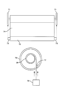
reference to Figure 3A. This figure illustrates a roller tube
38 to which fabric 74 and a weighted bottom rail 76 are
attached. A pair of end brackets 71 support the roller tube 38
and a pair of stops 73 extend from opposing ends of the rail 76.
The roller tube 38 is encased in a head-rail 75, which is
illustrated as having a circular cross section and having a
circumferential slot-type opening 77. The opening 77, through
which the fabric 74 extends, is circumferentially smaller than
the size of the bottom rail 76.
[0048] As illustrated in Figure 3A, one problem occurs when
an out-of-synch motor attempts to wind a fully retracted fabric
74. Such action, with the stops 73 pressed against the end
brackets 71, could result in straining the bottom rail 76 such
that it bends into and jams in the opening 77 in the head-rail
75. On the other hand, if the motor does not wind the fabric 74
-8-
CA 3056096 2019-09-20
far enough, an unsightly overhang of the fabric 74 will remain
after the retracting process concludes.
[0049] An out-of-synch motor creates different problems in
the unwinding operation of the motor. Some problems are
illustrated with reference to figures 3B-3E. These figures
illustrate several restraining means 79 for restraining excess
fabric 74 against the roller tube 38. Such restraining means 79
are desirable to set the drop height of a standard length
covering without requiring additional cutting and tailoring of
the fabric 74.
[0050] In Figure 3B, staples 79A and an axially extending
stiffening member 79B form the restraining means 79. In Figure
3C, the restraining means 79 include tape 79C. For example,
clear packing tape may be wrapped around excess fabric and a
topmost louver 79D in a louvered blind. In Figure 30, the
louvers are soft and/or have a profile curve enabling the
louvers to substantially fit against the curve of the wound
blind. The louvers are also illustrated as being glued 79E to
the blind.
[0051] In Figure 3D, a circumferential spring clip 79F,
extending axially along the full length of the fabric 74, forms
the restraining means 79. In Figure 3E, a cavity 791 with an
axial slot 79G is formed in the roller tube 38 in which an end
portion of the fabric 74 wraps around an axially extending
constraining member 79H.
[0052] In figures 3B-3D, unwinding the covering past the
predetermined drop height would result in an effort by the motor
to wind the fabric 74 so that it folds upon itself starting at
the maximum unwound point. This folding would take the fabric 74
away from the final stop point, undesirably retracting the
covering. This could also lead to excessive pulling of the
fabric 74; resulting in jamming in the head-rail as well as
-9-
CA 3056096 2019-09-20
potentially damaging the restraining means 79. For example, the
staples 79A and tape 790 could be pulled off and the spring clip
79F could deform. In Figure 3E, winding the fabric 74 in the
wrong direction could lead to stripping the fabric 74 from
within the cavity 79F.
[0053] In view of the challenges with setting and maintaining
limiter systems, some examples disclosed herein provide a motor
which does not require a limiter system for accurately winding
and unwinding the covering.
[0054] Some examples disclosed herein provide a motor
configuration which is unable to apply torque in an unwinding
direction. In some such implementations, the example motor is
configured to slip against a roller tube upon being subjected to
an opposing torque at a threshold level during a winding
operation. In some such implementations, the example motor is
insertable into and removable from an architectural opening
without requiring hard wiring of the motor to the architectural
opening. In some such implementations the example motor does
not require a limiter system for accurately winding and
unwinding the covering, avoiding the need to have to set top and
bottom winding points.
[0055] Figure 4 illustrates an example torque limiting motor
coupling 68 that prevents a motor from applying torque to a
roller tube 38 in an unwinding direction. The example
configuration of Figure 4 includes, for example, a motor output
shaft coupling 70 positioned on a motor shaft (not labeled). A
roller tube 38 is illustrated as an outer diameter of the
system, which is connected to the fabric 74 and, in turn, the
weighted rail 76. A track 78 is also illustrated which guides
the fabric 74 during winding and unwinding operations.
[0056] The motor output shaft coupling 70 functions as a
ratchet crank, where ratchet gear teeth 80 are part of the inner
-10-
CA 3056096 2019-09-20
diameter 36 of the roller tube 38 or are fitted thereto by an
additional adaptor (not illustrated). A pawl 82 is connected to
the motor output shaft coupling 70 by a pivot 84 and a
compression spring 86.
[0057] While the motor shaft is unwinding the fabric 74, the
pawl 82, locked against the gear teeth 80, prevents an
uncontrolled unwind which could otherwise occur from the weight
of the bottom rail 76. Similarly, when the motor shaft ceases
unwinding or winds in the take-up direction, the motor output
shaft coupling 70, with the pawl 82 locked against the gear
teeth 80, enables winding of the roller tube 38 so as to raise
the bottom rail 76 and retract the fabric 74 about the roller
tube 38. In other words, the torque applied by this motor
configuration, whether during an unwinding or winding operation,
is in the winding direction.
[0058] While unwinding, should the roller tube become
obstructed, for example, due to debris, the motor shaft 38 would
still turn. However, the pawl 82 and the gear 80, slipping
relative to each other, would be unable to apply torque in the
unwinding direction.
[0059] If an obstruction is in the track, a similar outcome
is achieved. When the rail 76 comes to rest on the obstruction,
and the fabric 74 has bunched up in the track 78, the motor
shaft 38 would still turn. Again, however, the pawl 82 and gear
80, slipping relative to each other, would be unable to apply
torque in the unwinding direction. Without the application of
torque in the unwinding direction, the fabric, with its weight
supported by the obstruction, will not continue to unwind from
the roller tube 38.
[0060] Figure 5 illustrates an example implementation of a
torque limiting motor coupling 88, which will now be discussed.
As with the torque limiting motor coupling 68, the torque
CA 3056096 2019-09-20
limiting motor coupling 88 is unable to apply torque in the
unwinding direction. Furthermore, the torque limiting motor
coupling 88 also slips against a roller tube upon being
subjected to opposing torque at a threshold level in a winding
direction.
[0061] Figures 6-8 illustrate example applications of the
torque limiting motor coupling 88, wherein the torque limiting
motor coupling 88 is retrofitted to the motor 10 illustrated in
Figures 1 and 2. This discussion illustrates an example
application of the torque limiting motor coupling 88, and
supports the discussion of the example application of the torque
limiting motor coupling 88, illustrated in Figures 9-12, and
discussed below.
[0062] Turning to Figures 5 and 6, the motor coupling 88
includes an adaptor shaft 90, which is a keyed cylinder, adapted
to fit outside of the distal end 32 of the shaft 30 of, for
example, the motor 18. Surrounding the adaptor shaft 90,
centered between opposing proximate end 91 and distal end, 93 of
the adaptor shaft 90, is a one-way bearing 92.
[0063] Functionally, the one-way bearing 92 is analogous to
the ratchet-pawl configuration of the torque limiting motor
coupling 68. That is, due to the one-way rolling of the outer
bearing race with respect to the adaptor shaft 90 (and thus with
respect to the shaft 30), the motor 18 is unable to apply torque
in the unwinding direction. A difference between the torque
limiting motor coupling 88 and the ratchet-pawl configuration 68
is, for example, the bearing is quieter than a ratchet-pawl
configuration. Furthermore, the torque limiting motor coupling
88 does not require a pivotable pawl 82 and also does not
require a mating gear structure 80 in the roller tube 38.
[0064] On the outer race 94 of the bearing 92, a slip-clutch
96 is provided. The slip-clutch 96 is designed to slip against
-12-
CA 3056096 2019-09-20
the bearing 92. Holding the slip-clutch 96 in place, on its
radial outer surface 98, is a spring 100. The selection of the
spring 100 (e.g., the spring force of the spring) defines the
threshold torque required to slip the slip-clutch 96 against the
bearing 92. The slip-clutch 96 is not illustrated in Figure 4;
however, it can be integrated into that configuration as well.
[0065] In the example torque limiting motor coupling 88 of,
for example, Figure 5, the bearing 92, the slip-clutch 96 and
the spring 100 are axially centered relative to each other and
have substantially the same axial dimension. The example shaft
90 is longer than the bearing 92, the slip-clutch 96 and the
spring 100. Among other things, this provides the proximate end
91 and the distal shaft end 93 with a small amount of material
for spacing the bearing 92, the slip-clutch 96 and the spring
100 from the axial base of the adapter shaft 90.
[0066] The axial buffer zone on both sides of the torque
limiting motor coupling 88 enables reversing the torque limiting
motor coupling 88 depending on whether a motor is placed on the
left or right hand side within a roller tube, due to, for
example, the location of available wiring. Reversing the torque
limiting motor coupling 88 is achieved by sliding the adaptor
shaft 90 off of the motor shaft 30 and reinstalling the adaptor
shaft 90 so that the distal end 93 of the adaptor shaft 90,
rather than the proximate end 91, faces the distal end 20 of the
motor 18.
[0067] An example cavity 102 is defined between opposing,
circumferentially spaced edges 104, 106 of the slip-clutch 96
and edges 108, 110 of the spring 100, rendering the slip-clutch
96 and spring 100 "C" shaped. Specifically, a base 112 of the
cavity 102 is the outer race 94 of the bearing 92. A first side
114 of the cavity 102 is defined by aligned edges 104, 108 of
the slip-clutch 96 and the spring 100. A second side 116 of the
-13-
CA 3056096 2019-09-20
cavity 102 is defined by aligned edges 106, 110 of the slip-
clutch 96 and the spring 100.
[0068] The example cavity 102 may be mated with a tang
manufactured in a modified crown coupling 118. An example tang
213 is illustrated in Figure 11, and discussed below. The
example tang 213 of Figure 11 has a radial inner surface 214
which does not reach the bearing 92, as well as opposing
circumferential surfaces 215, 216. The tang 213 moves
circumferentially between opposing sides 114, 116 of the cavity
102 so that one of the tang surfaces 215, 216 presses against a
respective one of the sides 114, 116 of the cavity 102, whereby
the tang 213 rotates with the slip-clutch 96. Thus, the
modified crown coupling 118 is capable of rotating with the
motor shaft 30.
[0069] Depending on the direction the tang moves in the
cavity 102, the bearing 92 will either roll or lock. If locked,
the slip-clutch 96 will slip when torque at the threshold limit
is applied. Accordingly, if a covering is obstructed during a
winding operation, the slip-clutch 96 slips when the torque of
the motor 18 reaches the threshold limit. The shaft 30 then
spins, without spinning the roller tube 38 as long as torque
above this threshold limit is maintained, preventing
overstraining of the motor 18 or the fabric of the covering.
[0070] The slip-clutch 96 configuration should be selected so
that slip occurs at a greater torque than required to wind the
fabric. On the other hand, the configuration should be selected
so that slip occurs at a lower torque than required to strain
the motor 18.
[0071] As an alternative to the slip-clutch 96, the motor 18
can be equipped with an overload system including one or more
sensors. For example, a mechanical torque based sensor and/or
an electrical current (e.g., amperage) based sensor (not
-14-
CA 3056096 2019-09-20
illustrated) may be used. This type of system would shut off
the motor 18 after mechanically sensing torque which exceeds a
threshold and/or sensing a current draw which exceeds a
threshold.
[0072] Before discussing the example application of the
torque limiting motor coupling 88 in Figures 9-12, it is noted
that the torque limiting motor coupling 88 is suitable for
implementation with the motor 18 of Figure 1 but not in the
motor 18 of Figure 2. As will now be examined, the torque
limiting motor coupling 88 will not affect the relationship
between the mechanical limiter system 46 and the actual wind
state of the covering in the motor 10 of Figure 1, but will
affect the relationship between the limiting system 60 and the
actual wind state of the covering in the motor 58 of Figure 2.
[0073] In the motor 18 of Figure 6, when the shaft 30 spins
without the roller tube 38 spinning during, for example, an
obstructed winding or unwinding operation, the passive ring 42
also does not spin and, therefore, the screw follower 52 does
not advance towards either switch 54, 56. With this type of
configuration, automatic timers may be used to time out the
system and avoid continual running of the motor 18.
[0074] In an operation immediately following an obstructed
winding or unwinding operation, the screw follower 52 would
engage the appropriate switch 54, 56 when the covering is
successfully wound or unwound. That is the free spinning of the
shaft 30 does not skew the relationship between the mechanical
limiter system 46 and the roller blind fabric 74.
[0075] On the other hand, were one to include the torque
limiting motor coupling 88 in the motor 58 of Figure 2, free
spinning of the motor 18 during an obstructed winding or
unwinding operation would cause the sensors 64, 66 to pass each
other with each revolution of the motor 18, despite the fact
-15-
CA 3056096 2019-09-20
that the roller tube 38 is stationary. The motor electronics 62
would falsely determine that the covering is being unwound or
wound.
[0076] Accordingly, Figures 7 and 8 illustrate a torque
limiting motor configuration 120 that may be used with the motor
58 of Figure 2. This configuration 120, as with the torque
limiting motor coupling 88, does not apply torque in the
unwinding direction.
[0077] The configuration 120 includes an alternative crown
coupling 122, which is connected to the inner surface 72 (shown
in Figure 8) of the roller tube 38. The crown coupling 122 of
the illustrated example is a solid disk with, for example, a
cavity 124 defined by a fifteen degree cut-out 129. The cavity
124 of the illustrated example has first and second sides 126,
128 and a base 130.
[0078] A motor shaft coupling 132 is connected to the distal
end 32 of the shaft 30 and axially aligned with the crown
coupling 122. The motor shaft coupling 132 of the illustrated
example is an elongated rectangular shaped member, connected at
one end to the shaft 30. The motor shaft coupling 132 has
opposing sides 134, 136 which can toggle between the opposing
sides 126, 128 of the crown coupling 122 when the motor 18
changes rotational directions. The approximately fifteen degree
angle between opposing sides 126, 128 allows the motor shaft
coupling 132 to pivot from one side of the cavity 124 to the
other. Similarly, top and bottom edges 138, 140 of the motor
shaft coupling 132 are sized to ensure that the motor shaft
coupling 132 can pivot from one side of the cavity 124 to the
other.
[0079] During an unwind operation, the weight of the rail 76
presses the side 126 of the cavity 124 against the side 134 of
the motor shaft coupling 132. To control the descent of the
-16-
CA 3056096 2019-09-20
blind, the torque applied by the motor is in the winding
direction.
[0080] When an obstruction prevents unwinding so that the
weight of the rail 76 is not pulling fabric from the roller tube
38, the roller tube 38 will stop spinning because the motor 18
is applying torque in the winding direction. However, the motor
shaft coupling 132, which still turns from the motor action,
will advance towards the opposing side 128 of the cavity 124.
This separates the side 126 of the cavity 124 from the side 134
of the motor shaft coupling 132. Communication of this
separation is transmitted to the motor controller electronics 62
by, for example, one or more sensors 142, 144, which may be
mechanical, magnetic, electromechanical, etc. The electronics
62 then stops the motor 18 and, therefore, prevents the motor 18
from applying torque in the unwinding direction, which would
unroll the fabric from the roller tube 38 while the fabric is
not falling due to the obstruction.
[0081] In the illustrated example, additional sensors 146,
148 on the opposing cavity 124 and motor shaft coupling 132
side surfaces 128, 136 render this configuration reversible as
well. However, in the example of Figure 7, contact between any
of the sensors is not required on the retracting phase, or at
least at the start of that phase because the mating sides 126,
134 (or, in the reversed configuration, sides 128, 136) would be
separated at the onset of the winding operation if, for example,
an obstruction stopped the previous unwinding operation.
[0082] On the other hand, an obstruction could be identified
in the winding direction by configuring the pairs of sensors
142, 144 and 146, 148 to sense different levels of applied force
between contacting surfaces 126, 134 and 128, 136. When the
applied force exceeds a threshold, a determination could be made
that an obstruction is present on the take-up cycle, and the
-17-
CA 3056096 2019-09-20
motor 18 could be disengaged. Alternatively, an electronic
torque sensor, motor amperage sensor, etc. could disengage the
motor 18 upon sensing the effects of an obstruction in the
winding operation.
[0083] Turning to Figures 9-12, example implementation of the
torque limiting motor coupling 88 in a rotary motor 156 will now
be discussed. The example rotary motor 156 is powered by a
timed-pulse of current. The bearing 92 and the slip-clutch 96
of the torque limiting motor coupling 88 enable the use of the
rotary motor 156 with a timer (not illustrated) rather than
using a stationary motor with a limiter system. As the timer
electronics are separate from the rotary motor 156, the rotary
motor 156 can be much smaller and lighter than stationary motors
equipped with limiting systems. According to the illustrated
example, while the stationary motor is described as having a
drive shaft that rotates with respect to the architectural
opening, the example rotary motor 156, as described in further
detail herein, includes a drive shaft that remains stationary
while the body (i.e., the casing, which is often labeled the
stator) of the motor rotates to drive rotation of a roller tube.
[0084] Other benefits of some implementations of a timer with
use of the illustrated example torque limiting motor coupling 88
on the rotary motor 156, over a motor with a limiting system,
will now be discussed. As indicated, known limiter systems use
set points to limit unwinding/winding a covering. The set
points must be set and reset frequently. Without the proper
configuration of the set points the problems associated with the
discussion related to Figures 3A-3E, above, could result.
[0085] However, the operation of a timed motor is different.
In some examples, when a timer period is calculated for
winding/unwinding the blind, a buffer is added to the timer
period. The example buffer ensures that, barring an
-18-
CA 3056096 2019-09-20
obstruction, there will be a period of time after the completed
winding/unwinding in which the motor keeps running. The buffer
can be, for example, ten percent of the predicted wind time.
[0086] With the buffered time period determined and set in
the example timing electronics, for the remainder of the life of
the covering, regardless of the introduction of temporary or
permanent obstructions, and regardless of whether the covering
is removed and reinstalled, the covering will continue to
operate without the need for set points or adjustments. This is
because, as will be discussed, unlike known limiter systems, the
example timed motor 156 is self-regulating.
[0087] For example, with the motor 156 equipped with the
torque limiting motor coupling 88 and a timer, when a full
winding/unwinding operation is successful, the motor 156 keeps
running during the buffer period when the blind has come to
rest. Before the motor 156 times out, if winding, the torque of
the motor 156 reaches the threshold level, causing the slip-
clutch 96 to slip against the bearing 92, avoiding the problems
associated with the discussion of Figure 3A. Similarly, if
unwinding, the outer bearing race rolls with respect to the
adaptor shaft 90 (and, thus, with respect to the drive shaft of
the motor 156) after the bottom rail of the covering comes to
rest or an obstruction is encountered, avoiding the problems
associated with the discussion of Figures 3B-3E. After timing
out, the motor 156 is ready for running in the reverse direction
in the next operation.
[0088] Faced with an obstruction during a winding/unwinding
operation, the torque limiting motor coupling 88 of the
illustrated example will respond as described with reference to
Figures 5 and 6. The example motor 156, however, instead of
deactivating due to limiter switches, will time out. In other
words, when an obstruction is encountered, the example motor 156
-19-
CA 3056096 2019-09-20
will continue to run while the covering is stationary until the
timer stops the motor 156.
[0089] An additional benefit of some example implementations
of the torque limiting motor coupling 88 with a timed motor 156
is realized following a partially successful unwinding/winding
operation, (e.g., obstructed winding/unwinding operation). In
such an instance, neither timer electronics nor the motor 156 is
aware of the state of the roller fabric 74. For example, an
obstruction in a track may allow the fabric 74 to unwind or wind
by only fifty percent before the timer stops the motor 156.
Therefore, upon removing the obstruction and restarting the
motor 156, an effort to continue in either operational direction
would be fifty percent too long (plus the buffer time).
[0090] Without the torque limiting motor coupling 88, the
timed motor 156 would induce the problems associated with
Figures 3A-3E in the next operation following a partially
successful winding/unwinding. However, these problems are
avoided in the illustrated example of the torque limiting motor
coupling 88 for the same reasons they are avoided with a
successful winding/unwinding operation, discussed previously.
That is, in a successful winding/unwinding operation immediately
following a partially successful winding/unwinding operation,
the motor 156 will continue to run after the blind comes to rest
because the blind will have a shorter distance to travel to be
fully wound/unwound. Thereafter, when the motor 156 times-out,
the motor 156 is correctly synchronized, (i.e., self-regulated),
for further winding and unwinding operations. In other words,
the covering will be fully wound or unwound and the timer period
will be appropriate for fully unwinding or winding the blind,
respectively.
[0091] In some examples, a remote control or wall switch
which is programmed for "up" and "down" commands if used to
-20-
CA 3056096 2019-09-20
control the covering. In such examples, no electronics need to
account for the wound state of the covering. With the torque
limiting motor coupling 88, there is no problem with
accidentally hitting "up" or "down" in consecutive operations
because the motor 156 cannot over-torque and damage the blind in
the illustrated example.
[0092] Turning to Figures 9-12, an example implementation of
the rotary motor 156 and the torque limiting coupling 88 will be
discussed. The orientation of the example motor 156 in Figures
9-12 is reversed as compared with the orientation of the motor
18 in Figures 1 and 2, in that the motor shaft 160 in the
example configuration of Figures 9-12 is on the right side of
the motor 156 rather than the left side. However, the "distal"
and "proximate" monikers have the same meaning here as before.
That is, with the motor 156 in a plan view, "axial proximate" or
"proximate" means closer to the right side of the figure. On
the other hand, "axial distal" or "distal" means further from
the right side of the figure.
[0093] In the example Figures 9-12, a roller tube 150 having
a proximate end 152 and a distal end 154 encloses the motor 156
and the additional components. The torque limiting motor
coupling 88 of the illustrated example is fitted on the
proximate end 158 of the motor 156 (e.g., on the motor drive
shaft 160), so that the distal end of the adaptor shaft 93 of
the torque limiting motor coupling 88 is positioned against a
distal end 162 of the drive shaft 160 of the motor 156.
[0094] An end cap 164, through which the motor drive shaft
160 connects with the torque limiting motor coupling 88,
securely connects the motor 156 to the roller tube 150. This
connection enables the motor 156 to turn with the roller tube
150, subject to slippage provided by the torque limiting motor
coupling 88, as discussed below.
-21-
CA 3056096 2019-09-20
[0095] As shown in Figure 11, the end cap 164 forms an
axially extending cup-type cavity having a distal base portion
168, and which opens on its proximate end 170. The cap base
portion 168 defines a radially central opening 172 which is
large enough for the adaptor shaft 90 of the torque limiting
motor coupling 88 to pass through.
[0096] The cap base portion 168 is axially between the
proximate end 158 of the motor 156 and the distal end 174 of the
bearing 92, slip-clutch 96 and spring 100 of the torque limiting
motor coupling 88. This configuration enables removal of the
torque limiting motor coupling 88 without disassembling the end
cap 164 and the motor 156 from each other and from the roller
tube 150. The rolling direction of the roller bearing 92 with
respect to the motor shaft 160 can be reversed without extensive
handling of the system to enable operation of the motor 156 in
either a left-handed or right-handed assembly.
[0097] A small amount of axial play 175 is provided between
the cap base portion 168 and the distal end 174 of the bearing
92, clutch 96 and spring 100 of the torque limiting motor
coupling 88. This configuration prevents binding of these
components during operation.
[0098] The cap base portion 168 is axially thick enough to
seat and physically isolate motor mounts 178 from the torque
limiting motor coupling 88. The motor mounts 178 include a
plurality of circumferentially spaced rubber bushings 180,
serving as vibration isolators, in which standoff mounts 182 and
screws 184 are inserted for connecting the end cap 164 to the
motor 156. In addition to the vibration isolation of the
elastic material of the bushings 180, the example bushings 180
also axially space the end cap 164 from the motor 156, to
further isolate vibrations of the motor 156.
-22-
CA 3056096 2019-09-20
[0099] The opened proximate end 170 of the end cap 164
includes a radially outward extending lip 186. The lip 186
seats against a proximate end 188 of the roller tube 150.
[00100] To fix the assembly of Figure 11 to the proximate side
of an architectural opening, the assembly is provided with a
stationary wall bracket 44 and screws 190. The wall bracket 44
of the illustrated example can slidably receive a stationary
tube bracket 192. The tube bracket 192 is removable and
insertable into the wall bracket 44 via a flexible extension 194
with a grip portion 196. A clip 198 of the illustrated example
securely connects the tube bracket 192 with the wall bracket 44
and can be released by flexing the grip portion 196.
[0100] Removing tube bracket 192 of the illustrated example
from the wall bracket 44 removes the covering assembly from the
architectural opening. On the other hand, inserting the tube
bracket 192 into the wall bracket 44 installs the covering
assembly into the architectural opening.
[0101] In the illustrated example, the proximate end 200 of a
drive ring 201 is fixedly connected to the distal side 199 of
the stationary tube bracket 192. These components are connected
via, for example, circumferentially spaced screws 202. The
drive ring 201 of the illustrated example is an axially
extending cup-type cavity having a proximate base 203, which
opens on its distal end 204. The distal end 204 has a diameter
enabling it to fit into the opening in the proximate end 170 of
the end cap 164. A radially inward step 205 at the drive ring
base 203 is adapted for being releasably gripped by
circumferentially spaced flexible gripping members 206 formed at
the end cap lip 186.
[0102] The drive ring base 203 of the illustrated example is
axially thick enough to seat and encase the screws 202 in
countersunk openings 208. The drive ring 201 is configured such
CA 3056096 2019-09-20
that when it is inserted into and encased by the end cap 164, a
distal surface 209 of the drive ring base 203 sits against the
proximate end 210 of the bearing 92, slip-clutch 96 and/or
spring 100 of the torque limiting motor coupling 88.
[0103] The drive ring base 203 of the illustrated example
includes an adaptor shaft support cavity 211. The cavity 211
which is an axially extending cup-type cavity formed in the
radial center of the drive ring base 203. The cavity 211 opens
into the drive ring 201. The support cavity 211 is large enough
to seat the proximate portion 91 of the adaptor shaft 90. The
shaft 90 extends axially past the proximate end 210 of the
bearing 92, clutch 96 and spring 100 components of the torque
limiting motor coupling 88.
[0104] As indicated above, in the illustrated example, the
length of the distal portion 93 of the adaptor shaft 90 is the
same or substantially the same as that of the proximate portion
91 of the adaptor shaft 90. This enables fitting the distal
portion 93 in the support cavity 211 for reversing the torque
limiting motor coupling 88 about the motor shaft 160, depending
on whether the covering is a left-handed or right-handed
assembly.
[0105] Between the distal end of the drive ring base 209 and
the distal end of the drive ring 204, the above mentioned tang
213 is provided. When inserted into the end cap 164, the distal
end of the tang 213 of the illustrated example, which defines
the distal end of the drive ring 204, is axially flush or
substantially flush with the distal end of the bearing 92,
clutch 96 and/or spring 174. This geometry provides a solid
connection between the tang 213 and the cavity 102 in the torque
limiting motor coupling 88.
[0106] As the drive ring 204 and tang 213 of the illustrated
example are stationary, movement in the motor 156 translates
CA 3056096 2019-09-20
into rotating the motor 156, not the tang 213. The connection
between the motor 156 and the roller tube 150 via the end cap
164 turns the roller tube 150 with the motor 156 so long as the
motor 156 is not rolling against the tang 213 via action of the
bearing 92 or slipping against the tang 213 via action of the
slip-clutch 96.
[0107] The tube bracket 192 of the illustrated example is
formed with an axially extending cup-type cavity 212. The cup-
type cavity 212 open on the distal end 199 of the tube bracket
192 for receiving the drive ring support cavity 211. The tube
bracket cavity 212 of the illustrated example is sized to seat
and encase the screws 202 connecting the tube bracket 192 to the
drive ring 201.
[0108] The above motor configuration provides a rotary drive
motor 156 for the covering. This configuration differs from
previous drive systems for coverings in which the motor is
stationary. It also differs from previous systems in that the
limiter system is replaced by electronics providing a timed-
pulse of power combined with the torque limiting motor coupling
88. With these components, the rotary motor 156 is self-
regulating when subjected to obstructions during a
winding/unwinding operation and/or when the covering is removed
and reinstalled.
[0109] Turning to Figures 13-14, an example structure for
providing power to the motor 156 will now be illustrated and
discussed. As indicated above, in a previous system, wire leads
are fixedly connected to the motor (e.g., motor 18) through an
architectural opening. Such a configuration has the drawback of
rendering the blind assembly difficult to install and difficult
to remove for servicing. Furthermore, such a configuration, by
itself, would not work with a motor 156 that rotates with the
roller tube.
-25-
CA 3056096 2019-09-20
[0110] As illustrated in Figure 13, in an example
configuration 228, to power the motor 156, batteries 230, which
also spin within the roller tube 38, are provided. In addition,
the configuration 228 includes a remote control switching device
232, which also spins within the roller tube 38 (i.e., rotates
with the motor 156).
[0111] Alternatively, as illustrated in Figures 9, 10 and 14,
a quick-release slip-ring 234 is utilized to carry power to the
spinning motor 156. Such a slip-ring 234 serves as an
electrical and mechanical disconnect point for the covering.
The electrical connection is provided between a rotating slip-
ring housing 236, at its distal end 238, and a stationary slip-
ring housing 240, which is attached to an architectural opening
(not illustrated) via, for example, screws 241.
[0112] Within the stationary slip-ring housing 240 of the
illustrated example is a spring contact 242 and a flat contact
244, electrically separated from each other. One of these
contacts 242, 244 is a hot contact and the other is a neutral
contact. These contacts 242, 244 are positioned within a cavity
246 in the stationary bracket 240, similar in type to the cavity
211 in the tube bracket 174.
[0113] Centrally disposed within the rotatable housing 236 is
a spring mounted pin 248 (e.g., a brass pin), with an associated
compression spring 250 and spring seat 251 fixed at an axially
intermediate location on the pin 248. An opening 252 in the
proximate side of the housing 236 is large enough to allow a
proximate end 254 of the pin 248 to pass, but not the spring
250. As such, the action of the spring 250 occurs between the
radial opening 252 and the spring seat 251, forcing the pin 248
in the distal direction from within the housing 236.
[0114] An insulating sleeve 256 fixed at the distal end of
the housing 236 has a proximate edge 258 against which the
CA 3056096 2019-09-20
spring seat 251 comes to rest, thereby restraining the pin 248
within the sleeve 256 and the housing 236. When the slip-ring
234 is connected to the stationary bracket 240, the spring 250
forces the distal end 258 of the pin against the flat contact
244.
[0115] The spring contact 242 of the illustrated example
comprises two contacts 260, 262, each extending axially from the
cavity 246 and each bent radially inward to press against an
exposed portion of a brass sleeve 264 on the outside of the
insulating sleeve 256. Wires 266, 268 are soldered to
respective points 270, 272 on the proximate end of the pin 248
and along a proximate end of the axial length of the brass
sleeve 264. The solder point 270 on the brass sleeve 264 is
positioned far enough towards the proximate end of the sleeve
264 to not obstruct axial motion of the contacts 260, 262
against the sleeve 264, as discussed below.
[0116] With the above configuration, when installed, an
electrical connection exists between the contact 244, the pin
248 and the wire 268. An electrical connection also exists
between the contact 242, the brass sleeve 264 and the wire 266.
The wires connect to the motor 156 for completing the power
circuit. One of the wires is connected to the hot contact on the
motor 156 and one is connected to the neutral contact on the
motor 156. Their connection to the pin 248 and brass sleeve 264
depends on which of these conductive members will be connected
to the hot contact or neutral contact at the stationary bracket
240, which is determined in advance.
[0117] The rotatable housing 236 of the illustrated example
includes a distal end lip 274, serving the same purpose of the
proximate end lip in the end cap 164. An axially extending cup-
shaped cavity 276 in the rotatable housing 236, which opens
-27-
CA 3056096 2019-09-20
towards its distal end 238, is radially large enough to enable
the contacts 260, 262 to flex against the brass sleeve 264.
[0118] The cavity 276 of the illustrated example is axially
deep enough to allow for axial play 278 between the rotatable
housing 236 and the stationary bracket 240 to account for
variations in bracket spacing, which is a function of the size
of the architectural opening. For the same reason, the axial
length of the exposed portion of the brass sleeve 264 of the
illustrated example, distal from the solder point 270 for the
wire 268, matches that of the depth of the cavity 276.
Similarly, the reach, from the pin 248 to the flat contact 244,
accounts for the same variations in axial play 278.
[0119] Accordingly, the above disclosed examples provide
quick-release slip-ring 234 which is capable of powering the
motor 156 without permanently wiring the motor 156 to wires at
an architectural opening. This configuration enables installing
and removing motorized coverings much more quickly and easily
than with typical connections.
[0120] A hard-wired slip-ring (not illustrated) could
alternately be utilized. For example, the motor 156 could be
operated in a same fashion even with a hard-wired slip-ring.
[0121] Examples disclosed herein provide a roller motor
configuration which does not apply torque in the unwinding
direction. Some such example motors are configured to slip when
encountering a torque above a threshold during a winding
operation. Some such example motors are also insertable into
and removable from an architectural opening without requiring
permanent wiring of the motor to the architectural opening.
Some example motors do not require a limiter system for stopping
the covering at the top and bottom of the stroke.
[0122] Turning to Figures 15 and 16, there is illustrated
another application of the torque limiting motor coupling 88 of
-28-
CA 3056096 2019-09-20
Figure 5. An example architectural opening treatment 278 is
known in the industry as Duette by Hunter Douglas, of 2 Park
Way, Upper Saddle River, New Jersey, 07458, in the United
States. This treatment 278 includes a head-rail 280, a pleated
fabric 282 and a bottom rail 284. A pair of lift spools 286,
288 are spaced within the head-rail 280, each having lift cords
290, 292 extending through the fabric 282. The lift spools 286,
288 are mounted to a single driven shaft 294 and controlled in
unison by a motor 296.
[0123] As illustrated in Figure 16, the prior Duette motor
can be fitted with the torque limiting motor coupling 88
illustrated in Figure 5. A coupling member 298, such as a cup-
shaped cylinder 300, opening towards its proximate side, is
fixedly connected to the spring 100 on the radial inner surface
of the coupling member 298, directly or through an additional
coupling. Furthermore, a base 302 of the coupling member 298 is
fixedly connected to a proximate end 304 of the driven shaft
294.
[0124] In such a configuration, the window treatment 278
exhibits described torque limiting characteristics as explained
above. That is, the motor in the Duette shade would not apply
torque in the unwinding direction and would slip with respect to
lift spools 286, 288 when encountering more than the threshold
torque when winding.
[0125] Figure 17 is a flowchart illustrating an example
method to control operation of an architectural opening
covering. The example method of Figure 17 is described in
conjunction with the roller tube 150 of Figure 9. However, the
example method may be used with any other covering.
[0126] The example method of Figure 17 begins when a
controller receives an instruction to wind the roller tube 150
(block 1702). For example, the controller may receive an
-29-
CA 3056096 2019-09-20
instruction from a wireless remote control via a wireless
receiver included with the controller, from a wired or wireless
remote control, from a button on a control panel, etc. In
response to the instruction, the controller operates the motor
156 in a winding direction (e.g., to raise a covering material
attached to the roller tube 150) (block 1704). As previously
described, the torque limiting motor coupling 88 prevents
rotation of the output shaft of the motor 156. Accordingly, the
radial body of the motor 156 and the roller tube 150 are
rotated. The controller determines if the torque on the motor
exceeds a winding torque threshold (block 1706). For example,
when a covering is wound to its upper-most limit, a bottom bar
or weight attached to the covering material will reach a frame
of the covering and prevent rotation of the roller tube 150
around which the covering material is wrapped. This stoppage
will cause the torque on the motor to increase beyond a
threshold. The threshold can be selected so that normal winding
(e.g., when no obstruction is present) does not exceed the
torque threshold, but winding against a frame or obstruction
will cause the threshold to be passed.
[0127] If the winding torque threshold has not been exceeded
(block 1706), the motor 156 continues to operate until the
threshold is exceeded. If the winding torque threshold has been
exceeded (block 1706), the motor is stopped (block 1708). For
example, when the covering is fully wound or an obstruction
preventing winding is encountered, the motor 150 will be
stopped. The method of Figure 17 then ends until a new
instruction is received at the controller.
[0128] The example method of Figure 18 begins when the
controller receives an instruction to unwind the roller tube 150
(block 1802). In response to the instruction, the controller
operates the motor 156 in an unwinding direction (e.g., to lower
-30-
CA 3056096 2019-09-20
covering material attached to the roller tube 150) (block 1804).
As previously described, the torque limiting motor coupling 88
prevents rotation of the output shaft of the motor 156.
Accordingly, the radial body of the motor 156 and the roller
tube 150 are rotated. The controller determines if the torque
on the motor exceeds an unwinding torque threshold (block 1806).
For example, when the covering is unwound to its lower-most
limit, the covering material may begin to wind on the roller
(e.g., raising the covering material). This winding will
increase the torque on the motor (e.g., to levels similar to the
levels found when operating the covering in winding). Thus, the
threshold can be selected so that normal unwinding does not
exceed the torque threshold, but winding the covering material
(e.g., after fully unwinding the covering material) will cause
the threshold to be passed. According to the illustrated
example, the winding threshold exceeds the unwinding threshold
so that end-of-material winding can be detected.
[0129] If the unwinding torque threshold has not been
exceeded (block 1806), the motor 156 continues to operate until
the threshold is exceeded. If the unwinding torque threshold
has been exceeded (block 1806), the motor is stopped (block
1808). For example, when the covering is fully unwound and
starts to wind, the motor 156 will be stopped. The method of
Figure 18 then ends until a new instruction is received at the
controller.
[0130] Figure 19 is a flowchart illustrating an example
method to control operation of an architectural opening
covering. The example method of Figure 19 is described in
conjunction with the roller tube 150 of Figure 9. However, the
example method may be used with any other covering.
[0131] The example method of Figure 19 begins when a
controller receives an instruction to wind the roller tube 150
CA 3056096 2019-09-20
(block 1902). For example, the controller may receive an
instruction from a wireless remote control via a wireless
receiver included in the controller, from a wired or wireless
remote control, from a button on a control panel, etc. In
response to the instruction, the controller starts a timer
(block 1904). For example, the timer may be set for a duration
that is long enough for a covering on the roller tube 150 to be
wound from its lower-most position to its upper-most position.
The timer may additionally include an additional time to account
for short delays in winding (e.g., a short amount of time during
which the covering is obstructed). Then, the controller
operates the motor 156 in a winding direction (e.g., to raise
covering material attached to the roller tube 150) (block 1906).
As previously described, a torque limiting motor control 88
prevents rotation of the drive shaft of the motor 156.
Accordingly, the casing of the motor 156 and the roller tube 150
are rotated.
[0132] The controller then determines if the winding timer
has expired (i.e., the winding time limit has been reached)
(block 1908). For example, the covering may have been wound
from its lower-most position to its upper-most position.
Alternatively, the covering may have been wound from an
intermediate position to its upper-most position. In such an
operation, the motor 156 would continue to run when the covering
reaches its upper most position while the torque limiting motor
coupling 88 slipped to prevent excessive torque from being
applied to the roller tube 150 until the timer expired. In
another instance, the covering may encounter an obstruction that
prevents fully winding the covering material. In such an
operation, the motor 156 would continue to run while the torque
limiting motor coupling 88 slipped to prevent excessive torque
-32-
CA 3056096 2019-09-20
from being applied to the roller tube 150 until the timer
expired.
[0133] If the winding timer has not expired (block 1908), the
motor 156 continues to operate until the timer expires. If the
winding timer has expired (block 1908), the motor is stopped
(block 1910). The method of Figure 19 then ends until a new
instruction is received at the controller.
[0134] Figure 20 is a flowchart illustrating an example
method to control operation of an architectural opening
covering. The example method of Figure 20 is described in
conjunction with the roller tube 150 of Figure 9. However, the
example method may be used with any other covering.
[0135] The example method of Figure 20 begins when a
controller receives an instruction to unwind the roller tube 150
(block 2002). For example, the controller may receive an
instruction from a wireless remote control via a wireless
receiver included in the controller, from a wired or wireless
remote control, from a button on a control panel, etc. In
response to the instruction, the controller starts a timer
(block 2004). For example, the timer may be set for a duration
that is long enough for the covering to be unwound from its
upper-most position to its lower-most position. The timer may
additionally include an additional time to account for short
delays in unwinding (e.g., a short amount of time during which
the covering is obstructed). Then, the controller operates the
motor 1808 in an unwinding direction (e.g., to lower covering
material attached to the roller tube 150) (block 2006). As
previously described, the torque limiting motor coupling
prevents rotation of the drive shaft of the motor 156.
Accordingly, the casing of the motor 156 and the roller tube 150
are rotated because the motor 156 no longer opposes unwinding of
-33-
CA 3056096 2019-09-20
the covering (e.g., where a weight attached to covering material
of the covering creates a torque to pull the covering material).
[0136] The controller then determines if the unwinding timer
has expired (i.e., the unwinding time limit has been reached)
(block 2008). For example, the covering may have been unwound
from its upper-most position to its lower-most position.
Alternatively, the covering may have been unwound from an
intermediate position to its lower-most position. In such an
operation, the motor 156 would continue to run when the covering
reaches its lower-most position while the torque limiting motor
coupling 88 prevented torque from being applied to the roller
tube 150 until the timer expired. In another instance, the
covering may encounter an obstruction that prevents fully
unwinding the covering material. In such an operation, the
motor 156 would continue to run while the torque limiting motor
coupling 88 slipped to prevent excessive torque from being
applied to the roller tube 150 until the timer expired.
[0137] If the unwinding timer has not expired (block 2008),
the motor 156 continues to operate until the timer expires. If
the unwinding timer has expired (block 2008), the motor is
stopped (block 2010). The method of Figure 20 then ends until a
new instruction is received at the controller.
[0138] Figure 21 is a flowchart illustrating an example
method to switch a motor control of an architectural opening
covering from a right-handed operation to a left-handed
operation (or vice versa). The example method of Figure 21 is
described in conjunction with the roller tube 150 of Figure 9.
However, the example method may be used with any other covering.
[0139] The example method of Figure 21 begins with removing
the drive ring 201 from the end cap 164 installed in the roller
tube 150 (block 2102). Then, the torque limiting motor coupling
88 is removed from the motor shaft 160 (block 2104). The torque
-34-
CA 3056096 2019-09-20
limiting motor coupling 88 is then reinstalled on the motor
shaft 160 in an axially reversed configuration (block 2106). In
other words, the torque limiting motor coupling 88 is
reinstalled so that the direction in which the torque limiting
motor coupling 88 prevents the motor 156 from applying torque to
the roller tube 150 is reversed. The drive ring 201 is then
positioned within the end cap 164 (block 2108). The roller tube
150 is then ready to be installed to operate in opposite
direction from its previous operation (e.g., left-handed
operation changed to right-handed operation or right-handed
operation to left-handed operation). A controller for the motor
150 can be instructed of the change to operate winding and
unwinding of the motor 156 in the appropriate directions
following the change.
[0140] Although certain example methods, apparatus and
articles of manufacture have been described herein, the scope of
coverage of this patent is not limited thereto. On the
contrary, this patent covers all methods, apparatus and articles
of manufacture fairly falling within the scope of the claims
either literally or under the doctrine of equivalents.
-35-
CA 3056096 2019-09-20