Note: Descriptions are shown in the official language in which they were submitted.
CA 03056183 2019-09-11
,
1
ROLLING DOOR
The invention relates to a rolling door comprising a door leaf which can be
moved between an
open position, in which it at least partially releases a wall opening and
forms a multi-layer
winding above the wall opening, and a closed position, in which it at least
partially closes the
wall opening, as well as comprising joint assemblies arranged in the region of
the lateral
edges of the door leaf, at least sections of which are running in the
direction of gravity in the
closed position, and secured to the door leaf, for guiding the door leaf
movement, each of
which includes a plurality of joint elements articulately connected relative
to joint axes
running perpendicular to the lateral edges and approximately parallel to the
door leaf plane.
Such rolling doors are described, for example, in DE 10 2009 017 767 Al. They
are employed
as so-called high-speed doors for locking industrial facilities among other
things. For this
task, it is critical that the door leaf movement is safely guided.
Furthermore, it should be noted
that there often is very little space for accommodating the door leaf in the
open position.
Regarding these requirements, the afore-mentioned document already provides
for a rolling
door, in which at least one joint assembly has at least one joint plate
mounted and secured to
an end face approximately perpendicular to the joint axis of a rigid door leaf
member
embodied, for example, as sandwich elements. Thus, an increase in thickness of
the overall
structure due to the joint assembly may be avoided and the space needed for
rolling doors in
the open position may be reduced. However, it has been found that such doors
still require a
significant amount of space and that the travel speed of the door leaf is
limited.
In light of these problems of the prior art, it is the objective of the
invention to provide a
rolling door that can be stowed in the open position with reduced space
requirements and
allows for high speeds during opening and closing, while ensuring reliable
guidance for the
door leaf movement.
According to the invention, this objective is achieved by a further
development of the known
doors generally characterized by forming at least sections of the door leaf
from a bendable
material windable relative to a winding axis perpendicular to the lateral
edges of the door leaf
and parallel to the door leaf plane, such as a plastic film or sheet, which is
stabilised by two,
three or more stabilising devices running perpendicular to the lateral edges
and in the door
leaf plane, wherein the door leaf is only connected to the joint assemblies
via the stabilising
devices.
CA 03056183 2019-09-11
2
Forming the door leaf at least partially from a bendable material allows for a
reduced required
space, since the material itself conforms to the winding to be formed in the
open position and
therefore allows for a low helix diameter in the open position. At the same
time, a robust door
leaf is achieved by the stabilising devices of the door leaf. The guiding of
the door leaf is
carried out by the joint elements of the joint assemblies, which are coupled
to the stabilising
devices, such that the pulling and pushing forces occurring during the door
leaf movement
may be transmitted via the joint assemblies. Accordingly, the door leaf can
weigh very little.
It just has to be ensured that the stabilising devices of the door leaf are
securely coupled to the
joint elements of the joint assemblies.
A commercially available, preferably transparent, PVC and/or polycarbonate can
be used as a
flexible material for manufacturing doors according to the invention. The
thickness of the
plastic sheet is selected based on the requirements. Using the bendable
material in the form of
a plastic film or sheet may ensure that the shape of the door leaf matches the
helical shape in
the open position, while maintaining a low winding radius.
Polycarbonate in particular has exhibited excellent properties for use in
doors according to the
invention. This material has a high resilience as well as sufficient bending
stiffness for
following the winding contour even at great widths. The material has further
positive
properties as well, such as a high impact resistance.
Thus, the inventive rolling doors combine the advantages of a rolling door
structure with rigid
blades and lateral joint assemblies with the advantages of film doors, in
order to provide a
high speed door that allows for high opening and closing speeds as a result of
the bendable
door leaf structure, while providing reliable guidance by the joint assemblies
and reducing the
stress on the door leaf by transmitting pushing and pulling forces via the
joint assemblies. A
particularly stable connection of the door leaf to the joint assemblies can be
achieved by using
the stabilizing devices already provided for avoiding bulges due to wind
loads. The stabilizing
devices in conjunction with the joint assemblies form a bending-resistant
framework or
skeleton for the bendable door leaf.
In one preferred embodiment of the invention the door leaf includes a segment
(hereinafter
also referred to as a "pane") made of a preferably transparent and bendable or
resilient
material with segment or pane edges approximately perpendicular to the lateral
edges of the
door leaf, the segment or pane edges being provided with a thickened area and
at least one
stabilising device having a stabilising profile including a receiving area for
receiving the
thickened portion on a segment or pane edge. The stabilising profile
advantageously spans the
CA 03056183 2019-09-11
3
entire width of the door leaf in a direction perpendicular to the lateral
edges of the door leaf,
the receiving area preferably extending along the entire width of the door
leaf as well.
Additionally or alternatively, at least one segment edge can be configured
without the
thickened portion and can be positively secured to the stabilising device,
such as by a
clamping strip.
In every embodiment of the invention the segment or pane may extend across
two, three or
more joint elements in the direction of the door leaf movement or a direction
running parallel
to the lateral edges of the door leaf. In this case, the joint elements
arranged between the
stabilising devices are connected to the door leaf indirectly through the
joint elements that are
directly connected to the stabilising devices.
The stabilising profile can be embodied as a plastic strand pressing profile,
for example.
However, in a particularly preferable embodiment of the invention the
stabilising profile is an
aluminium strand pressing profile. Such an aluminium strand pressing profile
combines high
strength with low weight.
The thickened portion on the segment or pane edges can be achieved by adhering
or welding
piping strips thereto, which are received positively into corresponding
receiving areas on the
stabilising profiles. However, other connection means are also contemplated,
such as via a
clamping strip that allows for easy exchanges of the bendable or resilient
segments when
installed.
In rolling doors according to the invention, the door leaf is only connected
to the joint
assembly, which can be configured as a hinge strap, for example, via the
stabilising profiles
that also serve as wind reinforcements. The lateral edges of each pane or door
leaf segment
may extend across two, three or more joint elements, wherein some joint
elements are only
connected to the door leaf segments or panes indirectly via the joint elements
that are directly
connected to the stabilising devices.
Within the context of the invention, attaching at least one segment edge to
the stabilising
device through a clamping element releasably fixable to the stabilising device
and preferably
received at least partially within the stabilising device and/or abutting the
stabilising device
has proven particularly useful. In this embodiment of the invention it is
particularly easy to
exchange each pane or door leaf segment by releasing the clamping element from
the
stabilising device and then removing the corresponding segment edge from the
stabilising
device. If both segment edges of a segment are attached to the stabilising
device through
CA 03056183 2019-09-11
4
respective clamping elements, the respective segment can be fully removed from
the door leaf
without affecting the framework or skeleton comprised of the joint assemblies
and the
stabilising devices.
In one particularly preferable embodiment of the invention the segment edge is
disposed
between the clamping element of a sealing strip releasably fixable to the
stabilising device to
provide a sealed transition between the stabilising device and the door leaf
segment.
The intermediate hinge points of the joint assembly or hinge strap are not
connected to the
bendable material. The hinge strap or joint assembly absorbs the pushing or
pulling forces
during opening and closing movements. The attachment of the stabilising
profiles or wind
reinforcements to the hinge strap can be implemented in any manner within the
hinge point
pattern. Thus, different pane heights can be achieved. For narrow doors, the
number of
stabilising profiles or wind reinforcements selected can be low, i.e. the
section height can be
large, while wide doors can be equipped with several stabilising profiles or
wind
reinforcements having smaller section heights for stabilisation.
Regarding the structure, it has proven useful to provide the door leaf with at
least two panes
arranged in series in the direction of the door leaf movement and made of a
bendable material,
the panes sandwiching a stabilising profile with two receiving areas for
receiving thickened
portions provided on pane edges facing each other. Thus, the stabilising
profile connects
adjacent panes of bendable material.
As discussed above, it has proven useful for obtaining a stable door leaf
structure to include at
least one stabilising device extending across a width of the door leaf
parallel to a joint axis. A
smooth attachment of the stabilising device without interfering with the
movement of the joint
assembly can be achieved by connecting the stabilising device to at least one,
preferably two
joint assemblies provided on opposing lateral door leaf edges.
Specifically with particularly high or wide door leaves, it has proven
advantageous for the
desired stabilisation to provide at least one reinforcing strip extending
approximately parallel
to the lateral door leaf edge and fastened to the door leaf. Using such
reinforcing strips, which
can also be, for example, adhered and/or welded to the door leaf panes,
sufficient overall
stability can be reached even though the material of the pane itself does not
provide sufficient
bending stiffness.
Similar to the rolling doors described in DE 10 2009 017 767 Al a rolling door
according to
the invention with a bendable door leaf may be associated with at least one
helical guide track
CA 03056183 2019-09-11
for guiding the door leaf movement and determining the open position of the
door leaf,
wherein at least one joint element may include a guide assembly on the side
thereof facing
away from the door leaf cooperating with the guide track in guiding the door
leaf movement,
advantageously including at least one guide roller, rotatably mounted relative
to a roller axis
running parallel to the joint axes, preferably received within a guide track
at least in the open
position of the door leaf
During operation of the known rolling doors with a door leaf consisting at
least partially of a
bendable material, such as a plastic film, and an oval-helical guide track for
guiding the door
leaf movement it has become apparent that high door leaf speeds may lead to
increased wear
on the guide track and the door leaf According to another aspect of the
invention, which can
be used advantageously in conjunction with the aspects of the invention
explained above, this
problem is solved by a door, specifically a rolling door, comprising a door
leaf which can be
moved between an open position, in which it at least partially releases a wall
opening and
forms a multi-layer winding above the wall opening, and a closed position, in
which it at least
partially closes the wall opening, and at least sections of which are formed
from a bendable
material, such as a plastic film, substantially characterized in that the
leading edge of the door
leaf during an opening movement is formed by a leading stabilising device
connected to an
edge of a segment made of a bendable material, which edge is uppermost in the
closed
position , in a non-rotary manner and connected to a guide arrangement in a
non-rotary
manner that cooperates with a guide track, which is preferably defined by
guide rails and at
least sections of which are curved.
This solution is based on the realization that, in the operation of
conventional doors, the
increased wear observed during high door speeds is caused by the upper edge of
the door leaf
of a bendable material is diverted while entering the helical guide track,
such that the door
leaf initially forms an inward bulge that later in the opening process
suddenly transitions into
an outward bulge which is maintained in the opening position. The sudden
change of the
inward bulge to the outward bulge during the opening movement leads both to
increased
stress on the door leaf itself as well as an increased radial load on the
guide track. This results
in the observed increase in wear.
The non-rotary attachment of the upper edge of a door leaf segment of a
bendable material to
the stabilising device that forms the leading edge of the door leaf during
opening movements
as well as the non-rotary attachment of the stabilising device to the guide
arrangement
cooperating with the guide track and following the course thereof leads to the
upper edge of
CA 03056183 2019-09-11
6
the door leaf segment of bendable material being forcibly diverted outward, as
the guide
arrangement enters the helical guide track, thereby forcing the door leaf
segment into an
outward bulge. This outward bulge of the upper segment is transmitted to the
subsequent
segments of the door leaf during the opening movement, if the subsequent
stabilising devices
between each door leaf segment are rotatably connected to the guide rollers to
be guided
through the guide track, wherein the roller axes can run parallel,
specifically coaxially, to the
joint axes of the articulately connected joint elements, as mentioned above.
In this manner, a
defined curvature of the door leaf during the opening movement can be ensured.
Therefore,
excessive loads on the door leaf and the guide track can be avoided and an
increase in wear
can be prevented.
The guide arrangement connected to the leading stabilising device in a non-
rotary manner
may include two, three or more guide pins or rollers arranged in series in the
direction of the
door leaf movement and attached to common carrier which is connected to the
leading
stabilising device in a non-rotary manner. By using two, three or more guide
pins or rollers
attached in series to a common carrier in the direction of the door leaf
movement and
cooperating with the guide rail enables the orientation of the guide
arrangement to
substantially follow the course of the guide track. Advantageously, the
carrier is attached to a
joint element leading during the opening movement which also allows for a non-
rotary
attachment of the carrier to the joint element. In case of a guide arrangement
including two,
three or more guide rollers arranged in series in the direction of the door
leaf movement, each
of them may be connected to the common carrier, which is connected to the
leading
stabilising device in a non-rotary manner, in a rotatable manner relative to a
roller axis
running parallel to the joint axes.
Instead of the conventional helical guide track, alternative guide tracks,
such as an oval helix,
a horizontal redirection or a vertical guide can be implemented depending on
the required
space of the structural body.
In every embodiment of the invention it has proven favourable to associate at
least one joint
element with a seal assembly that may abut a boundary surface of the door leaf
in the closed
position. In this context it has proven particularly advantageous for the
individual seal
assemblies associated with the joint elements to form a continuous sealing
strip in the form of
track seals in the closed position for engaging each segment or pane of the
door leaf or even
the entire lateral edges of the door leaf in the closed position.
CA 03056183 2019-09-11
7
In the context of the invention, embodiments in which the seal assembly abuts
the outer
boundary surface of the door leaf facing away from the space to be closed by
the door leaf are
also contemplated. However, it has been found that a particularly reliable
seal can be achieved
in cases, where the seal arrangement abuts the inner boundary surface of the
door leaf facing
away from the outer boundary surface and towards the space to be closed by the
door leaf.
This aspect of the invention is a result of a detailed kinematic analysis of
the door leaf
movement upon entering the helical guide track. During this phase of the
movement the door
leaf is pushed outwards and may thus impact a seal assembly outwardly adjacent
thereto
potentially leading to an increase in wear on the door leaf itself and on the
seal assembly.
However, if the seal assembly engages an inner boundary surface of the door
leaf, this cause
of wear is eliminated overall improving the seal.
As mentioned above, forming a continuous sealing strip in the form of track
seals from the
individual seal assemblies associated with the joint elements in the closed
position has proven
advantageous. In this context, embodiments are contemplated in which each seal
assembly
includes at least one sealing element extending across two, three or more
joint elements,
providing a gap-free seal across the corresponding number of joint elements.
Said sealing
elements may be attached to the joint elements by separate fasteners mounted
to the joint
elements. Alternatively or additionally, seal receivers may be integrated into
each joint
element. A composite of plastic and metal can be used for manufacturing the
joint elements
optionally including integrated sealing elements.
The door leaves of inventive doors may be moved into the open position at
particularly high
speeds. This requires some care, such that warpage of the door leaf in the
region of the door
leaf edge trailing during the opening movement may be avoided when reaching
the open
position and decelerating the door leaf as a result thereof. In this regard,
providing the
invention with a biasing device coupleable to an edge of the door leaf
trailing behind during
the opening movement throughout the opening movement, to decelerate the
opening
movement and provide a biasing force forcing the door leaf from the open
position into the
closed position has proven particularly useful. Coupling the biasing device to
the trailing edge
of the door leaf allows the lower region of the door leaf in the closed
position including the
edge trailing behind during the opening movement to be biased by the biasing
device in the
desired manner when reaching the open position. Thus, warpage of the door leaf
in the region
of the edge trailing behind during the opening movement may be avoided. In
addition, the
biasing device may provide a breakaway torque useful for initiating a closing
movement due
CA 03056183 2019-09-11
8
to the door leaf including the biasing device, optionally indirectly, coupled
to the edge thereof
trailing behind during the opening movement, being biased towards the closed
position.
In the context of the invention it has proven particularly advantageous for
the biasing device
to include a tension spring extending approximately in the direction of
gravity and embodied,
for example, as an elastic cord, i.e. a cord at least partially made of an
elastomeric material,
the upper end of which is captured and entrained by a driver attached in the
region of the
trailing edge of the door leaf in opening movements during the opening
movement.
Additionally or alternatively, the use of tension springs is also
contemplated.
In every embodiment of the invention kinematics suggest providing at least one
joint element
in a length more than 20mm, preferably more than 30mm and/or less than 400mm
in a
direction running parallel to the lateral edges in the closed position.
Hereinafter the invention will be explained with reference to the drawings
which are explicitly
referenced for all features essential to the invention and not set forth in
detail in the
description. In the drawings:
Fig. 1 shows a view of a rolling door in the closed position, according to the
invention;
Fig. 2 shows a partially cut away side view of a rolling door transitioning
from the closed
position into the open position, according to the invention;
Fig. 3 shows a detailed illustration of the door leaf of a rolling door
according to the
invention;
Fig. 4 shows a detailed illustration of the rolling door according to Fig. 1;
Fig. 5 shows an embodiment of a stabilising device of a door according to the
invention;
Fig. 6 shows another embodiment of a stabilising device of a door according to
the invention;
Fig. 7 shows detailed illustrations of a joint element of a joint assembly of
a door according to
the invention;
Fig. 8 shows illustrations of joint elements associated with seal assemblies
of a door
according to the invention;
Fig. 9 shows the attachment of a stabilising device of a door according to the
invention to a
joint assembly of a door according to the invention;
Fig. 10 shows detailed illustrations of a guide assembly of a door according
to the invention;
CA 03056183 2019-09-11
9
Fig. 11 shows a detailed illustration of the seal assembly of a door according
to the invention;
and
Fig. 12 shows a detailed illustration of a biasing device of a door according
to the invention.
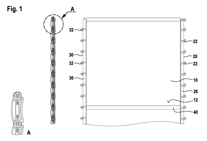
The rolling door shown in Fig. 1, comprises a door leaf, generally indicated
by 10, comprised
of panes 12 of a bendable, transparent material connected to each other via
stabilising
profiles 40. Joint assemblies in the form of hinge straps 20 and 30, connected
to the door
leaf 10 via the stabilising profiles 40, are disposed on the lateral edges of
the door leaf 10. The
hinge straps include guide rollers 22 and 32, respectively, on the joints
between each hinge
element on the side thereof facing away from the door leaf 10, which may guide
the door leaf
movement using suitable guide rails.
According to Fig. 1, each of the hinge straps 20 and 30 forming a push-pull
assembly consists
of hinge elements 26 and 36, respectively, having a fork-shaped receiver or
the like engaging
a stud of an adjacent hinge element. Both fork and stud are penetrated by a
common hinge
pin, causing an articulate connection between subsequent hinge elements. The
roller axes of
the guide rollers 22 and 32 run parallel to the joint axes, preferably
colinearly thereto.
Furthermore, the stabilising profiles 40 embodied as aluminium strand pressing
profiles run
parallel to the joint axes and roller axis. The stabilising profiles 40 may be
attached to the
joint assemblies 20 and 30 at the pivot points of the hinge straps.
According to Fig. 2, a rolling door according to the invention includes a
helical guide
track 100 entered by the guide rollers 22 and 32 attached to the hinge straps
20 and 30 upon
reaching the open position. In Fig. 2, the joint elements 26, 36 in the region
of the helical
guide track are hidden, to better illustrate the door leaf itself. As can be
seen, panes 12 of a
bendable material are able to easily conform to the desired helical shape. For
this purpose, no
connection of the panes 12 themselves to the hinge straps is required. Rather,
it is sufficient to
secure just the stabilising profiles 40 between each pane in the joint
assembly in the form of
the hinge straps 20, 30. It is further shown, that each pane of bendable
material may extend
across a substantial height of the door leaf. This constitutes an advantage
compared to
conventional sectional doors by allowing for minimization of the helical
diameter.
According to the Fig. 3, the panes 12 include thickened portions formed on the
pane edges
running perpendicular to the lateral edges by welding piping 14 thereto, the
thickened portion
being received within the receiving areas 42, 44 of the stabilising profiles.
The width of the
receiving areas 42 and 44 tapers from the receiving areas 42 and 44 in a
radial direction, such
CA 03056183 2019-09-11
that the receiving areas only permit passing of the panes 12 with piping
strips adhered thereto,
but not passing of the thickened portion or piping 14. The result is a secure
connection of
individual panes via the stabilising profiles 40. However, no transmission of
pulling or
pushing forces by said connections is necessary. The forces are transmitted by
the hinge straps
20, 30 instead.
According to Fig. 4, the attachment of the hinge straps 20, 30 via the
stabilising elements 40
is achieved using a screw running colinearly to the roller axes of the guide
rollers 22, 32 and
secured by a lock nut 50. The screw engages a corresponding recess 52 (see
Fig. 3) within the
stabilising profiles 40. Fig. 4 shows that the joint axis of the articulate
connection between
adjacent hinge elements 26, the roller axis, the screw axis and the axis of
the stabilising
profile 40 are all approximately colinear.
The embodiment according to the invention shown in Fig. 5 essentially differs
from the
embodiment discussed with reference to the Fig. 3 in that the stabilising
profile 140 includes
two receiving areas 142 and 144 configured to receive a clamping element 150
(see Fig. 5b)
and a sealing strip 160 (see Fig. Sc). When assembled, the clamping element
and the sealing
strip are received within the receiving areas 142 and 144 with a segment or
pane edge
sandwiched between the clamping element 150 and the sealing strip 160 (see
Fig. 5d).
The embodiment according to the invention shown in Fig. 6 essentially differs
from the
embodiment discussed with reference to Fig. 5 in that the clamping element 250
confines the
stabilising device 240. This is done by clipping the clamping element 250 into
the stabilising
profile 240, as shown in Fig. 6. In this embodiment of the invention the edge
of the pane 212
is again sandwiched between the clamping element 250 and the sealing strip
260, when
assembled, wherein the sealing strip 260 is received within a corresponding
receiver of the
stabilising profile through a fastening bead.
Fig. 7a shows joint elements 126 embodied as aluminium strand pressing
elements,
illustrating the attachment of the rollers 122 to the joint assembly via slide
bearings.
Fig. 7b shows joint elements embodied as a plastic injection moulded hybrid
having a plastic
injection moulded shell and a sheet steel core.
In the embodiment of the invention shown in Fig. 8, a seal assembly 370 is
placed onto joint
elements 360. The seal assembly 370 includes a sealing strip 380 which forms a
continuous
seal when closed due to the sealing strip 380 extending across a plurality of
joint
CA 03056183 2019-09-11
11
elements 360. The sealing strip may engage an outer boundary surface of each
segment or
pane of the door leaf when closed.
Fig. 9 illustrates the attachment of the stabilising profiles 240 to the joint
assembly via screw
bolts running colinearly to the joint axes, wherein the stabilising profile is
mounted to the
joint assembly and the guide rollers are mounted to the joint assembly.
In the embodiment of the invention shown in Fig. 10, the leading edge of the
door leaf during
opening movements is formed by a stabilising device 40 connected to a guide
assembly
generally indicated by 60 in a non-rotary manner. The guide assembly comprises
a roughly U-
shaped bracket 62. An outer leg of the U-shaped bracket 62 is fastened to the
stabilising
device 40 via a pin 64 and a locking screw 66. The pin 64 and the screw 66 are
spaced apart
in the direction of the door leaf movement indicated by arrow P. Thus, a non-
rotary
attachment of the bracket 62 to the stabilising device 40 is achieved. Two
guide rollers 22
arranged in series in the door leaf movement direction P are secured to the
bracket 62, each
fastened to the bracket 62 in a rotatable manner relative to roller axes
running parallel to the
joint axes of the joint or hinge elements 26. The bracket 62 is further
connected to the hinge
or joint element 26 leading during opening movements in a non-rotary manner.
In Fig. 10b the door leaf equipped with the guide assembly 60 is shown
entering the helical
guide track. By forcibly guiding the guide rollers 22 mounted to the bracket
62 the stabilising
device 40 connected to the guide assembly 60 in a non-rotary manner and the
edge of the
disc 12 leading during opening movements and connected thereto in a non-rotary
manner are
entrained and/or oriented along the guide track, forcibly bulging the disc 12
in an outward
direction. This bulge is transmitted to the subsequent discs of the door leaf
due to the
connection of the stabilising devices 40 provided between each pane 12 to the
guide rollers 22
rotatable relative to a roller axis running colinearly to the joint axes of
the joint elements. By
forcibly guiding the guide assembly 60, the guide rollers 22 mounted thereto,
the stabilising
device 40 connected thereto and the upper edge of the leading segment during
opening
movements or the leading pane 12 during opening movements connected to the
stabilising
device 40 an uncontrolled transition of the disc 12 and the subsequent discs
12 from an inner
bulge to an outer bulge may be avoided, thereby increasing the resistance to
the wear of the
inventive door.
Further, the embodiment of the invention shown in Fig. 10 differs from the
embodiments of
the invention shown with reference to Figs. 1 to 4 in that each joint element
includes two
fork-shaped receivers on one side thereof and studs engaging with the fork-
shaped receivers
CA 03056183 2019-09-11
12
of an adjacent joint element on the other side thereof. This results in an
improved winding
stiffness of the joint assembly.
The embodiment of the invention shown in Fig. 11 illustrates a seal assembly
470 abutting an
inner surface of the panes 12 facing toward the space to be closed by the door
leaf. The seal
assembly 470 comprises a U-shaped sealing profile extending across one, two,
three or more
joint elements 26, from which a sealing lip 472 extends towards an inner
boundary surface of
the disc 12.
The sealing lip 472 is equipped with a cavity seal 474 on an edge thereof
facing the inner
boundary surface of the pane 12, the cavity seal achieving a particularly
reliable sealing
effect. The sealing profile 476 of the seal assembly shown in Fig. 11 may
extend across two,
three or more joint elements extending between adjacent stabilising devices
240. In general,
the seal assembly 470 extends approximately in the direction of gravity in the
closed position
of the door leaf.
Fig. 12 shows a top perspective view of one of two lateral edge profiles 600
of a door
according to the invention. The lateral edge profile 600 includes a channel
610 running in the
direction of gravity, receiving a tension spring 500, the upper end of which
can be seen in
Fig. 12. A cantilever arm 520 is mounted to the upper end of the tension
spring 500, wherein a
driver (not shown) mounted to the lower joint element 26 trailing during
opening movements
comes to rest on the arm during the opening movement. The driver may entrain
the arm 520
and thus the upper end of the tension spring 500 in an upward direction during
the opening
movement, thereby tensioning the tension spring 500. Consequently, the opening
movement
of the door leaf is decelerated and a breakaway torque promoting initiation of
a closing
movement is provided in an open position.
The invention is not limited to the embodiment discussed with reference to the
drawing.
Rather, adding additional stabilising strips parallel to the lateral edges of
the door leaf
providing additional stabilisation with respect to wind loads is also
contemplated.
Furthermore, the push-pull assemblies implemented in the form of hinge straps
in the
embodiment described may be implemented in a different manner. The connection
of the
stabilising elements to the push-pull assembly may also be configured
articulately without a
rigid connection. Thus, a floating bearing is created that helps avoid
transmission of torsional
forces from the winded segments to the push-pull assembly.
CA 03056183 2019-09-11
13
List of reference numerals
P direction of door leaf movement
20/30 hinge straps
22/32 guide rollers
26/36 hinge elements
42/44 receiving areas
door leaf
12 panes
14 piping
40 stabilising profile
50 locking nut
52 recess
60 guide assembly
62 bracket
64 pin
66 locking screw
100 guide track
122 rollers
126 joint elements
140 stabilising profile
142 receiving area
144 receiving area
150 clamping element
160 sealing strip
212 pane
CA 03056183 2019-09-11
. 14
240 stabilising device
250 clamping element
260 sealing strip
360 joint elements
370 seal assembly
380 sealing strip
470 seal assembly
472 sealing lip
474 cavity seal
476 sealing profile
500 tension spring
520 arm
600 lateral edge profile
610 channel