Note: Descriptions are shown in the official language in which they were submitted.
SOLAR CELL STRIP, SOLAR CELL AND SOLAR CELL MODULE
TECHNICAL FIELD
[0001]
The present invention relates to the field of photovoltaics, and in particular
to a
.. solar cell strip, a solar cell and a solar cell module with lower
resistance.
BACKGROUND
[0002]
Nowadays, shingled module with a relatively higher conversion efficiency is
one
of the development directions of the solar cell module.
[0003] The shingled module is formed by a plurality of solar cell strips.
The adjacent
solar cell strips in said shingled module are partially overlapped with each
other and bonded
by a special conductive adhesive. Thus, the solar cell strips can be arranged
more closely, the
gaps in the shingled module will be decreased; and more solar cell strips can
be set in a same
solar cell module model, which can increase the light absorption area.
Besides, as described
above, the bonded connection between adjacent solar cell strips will not need
any solder strip,
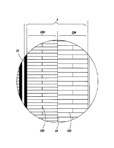
which reduces the manufacture cost.
[0004]
However, FIG. 1 is a schematic view of a front surface of a traditional solar
cell,
as shown in FIG. 1, The traditional solar cell 100' comprises a plurality of
elongated cell
units 1'. The elongated cell unitsl' can be separated to form a plurality of
traditional solar cell
strips. The metallization pattern on a front surface of a traditional solar
cell strip is of
comb-shaped. When the traditional solar cell strips are overlapped and bonded
to formed a
shingled module the resistance loss of front metallization pattern is
relatively higher. As a
result, the conversion efficiency of the shingled module will be difficult to
increase.
[0005]
In view of this, it is necessary to provide an improved solar cell strip, a
solar cell
and a solar cell module.
SUMMARY
[0006]
In view of this, the present invention provides a solar cell strip, a solar
cell and a
solar cell module, in order to reduce the resistance loss and emitter
resistance of front
metallization pattern.
[0007]
According to an aspect of the present invention, the present invention relates
to a
solar cell strip. The solar cell strip includes a front busbar positioned
adjacent to one side
edge of a front surface of the solar cell strip; and at least two finger
regions arranged side by
side at one side of the front busbar along a first direction which is
perpendicular to the front
6433173
Date Recue/Date Received 2021-03-25
busbar. Each patterned region is provided with a plurality of finger
electrodes electrically
connecting with the front busbar. The density of the finger electrodes in said
at least two
patterned regions is gradually decreased in the first direction.
[0008] According to another aspect of the present invention, the present
invention relates
to a solar cell. The solar cell includes a plurality of elongated cell units
which are
sequentially arranged in a direction. The elongated cell units are designed as
said solar cell
strip.
[0009] According to another aspect of the present invention, the present
invention relates
to a solar cell module. The solar cell module includes a plurality of solar
cell strings arranged
in physically parallel rows. Each solar cell string includes a plurality of
said solar cell strips.
The solar cell strips are connected by overlapping edges of adjacent solar
cell strips.
BRIEF DESCRIPTION OF THE DRAWINGS
[0010] The components in the drawing are not necessarily drawn to scale,
the emphasis
instead being placed upon clearly illustrating the principles of the described
embodiments. In
the drawings, reference numerals designate corresponding parts throughout
various views,
and all the views are schematic.
[0011] FIG. 1 is a schematic view of a front surface of a traditional
solar cell;
[0012] FIG. 2 is a schematic view of a front surface of a solar cell
according to a first
preferred embodiment of the present invention;
[0013] FIG. 3 is an enlarged view of the circled portion shown in FIG.
2;
[0014] FIG. 4 is a schematic view of a front surface of a partial solar
cell according to
another preferred embodiment of the present invention;
[0015] FIG. 5 is a schematic view of a front surface of a solar cell
according to a second
embodiment of the present invention;
[0016] FIG. 6 is an enlarged view of the circled portion shown in FIG.
5;
[0017] FIG. 7 is a schematic view of a front surface of a solar cell
according to a third
embodiment of the present invention;
[0018] FIG. 8 is an enlarged view of the circled portion shown in FIG.
7;
[0019] FIG. 9 is a schematic view of a part of a solar cell string of a
solar cell module
according to a preferred embodiment of the present invention; and
[0020] FIG. 10 is an enlarged view of the circled portion shown in FIG.
9.
2
6433173
Date Recue/Date Received 2021-03-25
DETAILED DESCRIPTION
[0021] Exemplary embodiments will be described in detail herein,
examples of which are
illustrated in the accompanying drawings. However, these embodiments do not
limit the
present application. Modifications to the structure, method or function based
on these
embodiments and made by those skilled in the art are all also included in the
protection scope
of the present application.
[0022] In the various figures of the present application, some
dimensions of a structure or
portion may be exaggerated relative to other structures or portions for ease
of illustration, and
thus, are merely used to illustrate the basic structure of the subject matter
of the present
application.
[0023] Referring to Figs. 2-8, the present invention provides some
preferred
embodiments of solar cell 100. The solar cell 100 is a standard square wafer
and comprises a
plurality of elongated cell units which are sequentially arranged in a
direction and a plurality
of gaps between adjacent elongated cell units. The elongated cell units can be
diced along the
gaps to form a plurality of solar cell strips 1, so that, there is no
electrodes breakage in any
solar cell strip 1. Thereby the present invention further provides a solar
cell strip 1.
[0024] Usually, the elongated cell units on a solar cell 100 are
identical in shape,
metallization pattern design and the like, such that the solar cell strips 1
diced from there are
similar, and a solar cell module formed by the solar cell strips 1 will be
neat and attractive in
appearance. Certainly, the elongated cell units also can be designed
differently in shape,
metallization pattern design and the like to meet different requirements.
Besides, the number
of the solar cell strips 1 diced from a same solar cell 100 is determined by
the area of the
solar cell 100, as well as the shape and the area of the solar cell strip 1.
[0025] Refer to Figs 2 and 3, in the preferred embodiment of the present
invention, each
solar cell 100 includes identical six elongated cell units each of which
having a front
metallization pattern on a front surface thereof and a rear metallization
pattern on a rear
surface thereof. Then the solar cell 100 can be diced to six identical solar
cell strips 1 for
facilitating the follow-up manufacturing process of a shingled solar cell
module. The
metallization patterns designed on the elongated cell units and the solar cell
strips 1 are same,
and the metallization patterns on the solar cell strips 1 will be chosen to be
detail described in
following.
[0026] The front metallization pattern formed on each solar cell strip 1
comprises a front
busbar 11 and a plurality of finger electrodes 121 electrically connected with
the front busbar
11. The rear metallization pattern formed on each solar cell strip 1 comprises
a rear busbar.
3
6433173
Date Recue/Date Received 2021-03-25
The front busbar 11 and the rear busbar are disposed at two opposite edges of
the solar cell
strip 1 respectively, such that the solar cell strip 1 can be connected in
series with other solar
cell strips 1 in a shingled manner.
[0027]
The present invention aims to improve the efficiency of the solar cell strip 1
or the
solar cell module by improving the design of the finger electrodes 121 on the
front surface.
The design of the rear metallization pattern on the rear surface adopts the
prior art, which will
not be repeated herein.
[0028]
The front busbar 11 is positioned adjacent to one side edge of the front
surface of
the solar cell strip 1. In the present invention, the front busbar 11 extends
parallel to the long
side edge of the solar cell strip 1, and the finger electrodes 121 are
disposed at one side of the
front busbar 11, thereby the finger electrodes 121 will have a shorter
transmission path,
which can improve transmission efficiency.
[0029]
Refer to Figs. 2 and 3, each solar cell strip 1 can be formed with at least
two
patterned regions 12 that are sequentially arranged side by side at one side
of the front busbar
11 along a first direction which is perpendicular to the front busbar 11. The
finger electrodes
121 are distributed in the patterned regions 12. In the present invention, the
density of finger
electrodes 121 in said at least two patterned regions 12 is gradually
decreased in the first
direction.
[0030]
In detail, the finger electrodes 121 in a same patterned region are parallel
to each
other. Said at least two patterned regions 12 include a first patterned region
123 and a second
patterned region 124 away from the busbar 11 than the first patterned region
123. The
distance between adjacent finger electrodes 121 in the second patterned region
124 is larger
than that in the first patterned region 123. Simply, the farther the patterned
region 12 is from
the front busbar lithe smaller the density of finger electrodes 121 in the
patterned regions 12
is. The decrease of the density can be an equal difference decrease or any
difference decrease.
[0031]
Compared with a traditional comb-shaped metallization patterns, the finger
electrodes disposed on the solar cell strip 1 of the present invention are
divided into segments,
which make the finger electrodes 121 be shorten, thus the resistance loss of
the finger
electrodes 121 is decreased. Besides, the above setting of the density can
further reduce the
resistance of the front metallization pattern and the resistance of the
emitter, and improve the
conversion efficiency of the solar cell module, which all based on the premise
of increasing
neither the difficulty of the manufacturing process of the solar cell strip
nor the
light-shielding area of the metallization patterns.
[0032]
Further, the finger electrodes 121 in different patterned regions have a same
shape
4
6433173
Date Recue/Date Received 2021-03-25
or different shapes. Please refer to Figs. 2 to 8, in the preferred embodiment
of the present
invention, the finger electrodes 121 in all patterned regions are parallel to
the short side edge
of the solar cell strip 1 and perpendicularly connected with the front busbar
11, which make
the finger electrodes 121 be shortest.
[0033] Besides, the length of the finger electrodes 121 in different
patterned regions can
be same or different. When the length of the finger electrodes 121 in
different patterned
regions is different, the length of the finger electrodes 121 in the patterned
region close to the
front busbar 11 should be shorter than that of the finger electrodes 121 in
the patterned region
far from the front busbar 11, which can meet the demand of that the finger
electrodes 121
close to the front busbar 11 bear relatively larger charge transport.
[0034]
For example, in the first embodiments as shown in Figs. 2 to 4, the finger
electrodes 121 in the first and second patterned regions 123,124 have a same
length. In a
second embodiment as shown in Figs. 5 and 6, the length of the finger
electrodes 121 in the
first patterned region 123 is shorter than that of the finger electrodes 121
in the second
patterned region 124. In a third embodiment as shown in Figs. 7 and 8, said at
least two
patterned regions further include a third patterned region 125 away from the
front busbar 11
than the second patterned region 124, and the length of the finger electrodes
121 in the first
patterned region 123 is shorter than that of the finger electrodes 121 in the
third patterned
region 125. The length of the finger electrodes 121 in the second patterned
region 124 is
same as that of the finger electrodes 121 in the first or the third patterned
region 125.
[0035]
In addition, in the present invention, as shown in Figs. 2 to 8, there are a
plurality
of first connecting lines 13 disposed on the front surface to connect the
finger electrodes 121
of two adjacent patterned regions. Then the finger electrodes 121 in the
patterned regions 12
far from the front busbar 11 are communicated with the front busbar 11 through
the finger
electrodes 121 in the patterned regions 12 closer to the front busbar 11 and
the first
connecting lines 13.
[0036]
Preferably, the first connecting lines 13 are disposed at the junction of two
adjacent patterned regions.
[0037]
Refer to Figs. 2 to 8, Preferably, the first connecting lines 13 are set to be
connected one by one in a direction which is perpendicular to a length
direction of the finger
electrode 121, which means that the first connecting lines 13 are formed as a
continuous
longer line to continuously connect all the finger electrodes 121 of said two
adjacent
patterned regions together. In an alternative embodiment, the first connecting
lines 13 can be
set to discontinuously connect some finger electrodes 121 of said two adjacent
patterned
5
6433173
Date Recue/Date Received 2021-03-25
regions 12 also.
[0038]
Refer to Fig. 2, the first connecting lines 13 extend lineally and
perpendicularly
connect with the finger electrodes 121. In an alternative embodiment, the
first connecting
lines 13 also can extend in a wave manner as shown in Fig. 4, or the like.
[0039] Moreover, at least one of the patterned regions is further provided
with a plurality
of second connecting lines 122 perpendicularly connected with adjacent finger
electrodes 121,
such that the impact on the conversion efficiency of the solar cell stripl
from the finger
electrodes breakage caused by a manufacturing process of the metallization
patterns is
decreased, and power output may not be adversely affected by a potential
cracking.
Preferably, the second connecting lines 122 are connected with the middle
position of the
finger electrodes 121.
[0040]
In detail, refer to Figs.2 to 6, the second connecting lines 122 are
discontinuously
disposed between adjacent finger electrodes 121. In an alternative embodiment,
the second
connecting lines 122 can be set as the first connecting lines 13 to connect
one by one along an
arrangement direction of the finger electrodes 121 to form a continuous long
communicating
line.
[0041]
Besides, such as shown in Figs. 2-4, the second connecting lines 122 can be
set in
all the patterned regions. The second connecting lines 122 also can be
alternatively set in the
patterned region with longer finger electrodes 121, such as shown in Figs. 5
and 6.
[0042] Of course, refer to Fig. 7 and 8, in another alternatively
embodiment, there are
only disposed with the first connecting lines 13, without any second
connecting lines 122.
[0043]
Preferably, the diameter of the first connecting lines 13 is wider than that
of the
finger electrodes 121 to form an effective charge transport path for
transmitting more
charges.
[0044] Moreover, the present invention further provides a solar cell module
200. The
solar cell module 200 comprises a plurality of solar cell strings 1 arranged
in physically
parallel rows.
[0045]
Such as shown in Fig. 9 and 10, the solar cell module 200 is provided with a
plurality of solar cell strips 1 as mentioned above. The solar cell strips 1
are connected by
overlapping edges of adjacent solar cell strips with conductive adhesive.
[0046]
In summary, compared with a traditional comb-shaped metallization patterns,
the
sectioned patterned regions in the present invention make the finger
electrodes be shortened,
then the resistance loss of the finger electrodes 121 is decreased. Besides,
the above setting of
the density of the finger electrodes 121 in different patterned regions can
further reduce the
6
6433173
Date Recue/Date Received 2021-03-25
resistance of the front metallization pattern and the resistance of the
emitter, and improve the
conversion efficiency of the solar cell module, which all based on the premise
of increasing
neither the difficulty of the manufacturing process of the solar cell strip
nor the
light-shielding area of the metallization patterns. Thus, the conversion
efficiency of the solar
cell module is increased.
[0047] It should be understood that although the description is
described according to the
above embodiments, each embodiment may not only include one independent
technical
solution. The presentation manner of the description is only for the sake of
clarity. Those
skilled in the art should take the description as an integral part. The
technical solutions of the
respective embodiments may be combined properly to form other embodiments
understandable by those skilled in the art.
[0048] The above detailed description only illustrates the feasible
embodiments of the
present application, and is not intended to limit the protection scope of the
present
application. Equivalent embodiments or modifications within the scope and
spirit of the
present application shall be embraced by the protection scope of the present
application.
7
6433173
Date Recue/Date Received 2021-03-25