Note: Descriptions are shown in the official language in which they were submitted.
I
TITLE OF THE INVENTION
PORTABLE TENT PLATFORM
FIELD OF THE INVENTION
[0001] The present invention relates to the general field of platforms and is
more
specifically concerned with a portable tent platform.
BACKGROUND
[0002] A tent set on irregular, rough or humid ground can be uncomfortable for
its
occupants. There are ways of improving comfort, such as, for example,
supporting
the tent above the ground. However, existing structures used to that effect
require
a frame and other relatively bulky and heavy components, which ,may be
inconvenient to carry to a campsite.
[0003] Against this background, there exists a need in the industry to provide
an
improved tent platform. An object of the present invention is therefore to
provide
such an improved tent platform.
SUMMARY OF THE INVENTION
[0004] In a broad aspect, there is provided a portable tent platform supported
on a
ground area, the portable tent platform including: a flexible support sheet
defining
a sheet peripheral edge; at least three legs, each leg defining a leg top end
portion
and an opposed leg bottom end portion, the leg bottom end portion being
supported on the ground area, the flexible support sheet and each leg top end
portion being secured to each other at a respective sheet mounting location of
the
=
CA 3056246 2019-09-20
2
flexible support sheet, the sheet mounting locations being located at vertices
of a
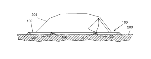
polygon defining a centroid; and at least three anchors anchored into the
ground
area and each extending from a respective one of the leg top end portions
generally away from the centroid; the flexible support sheet being maintained
under tension through the anchors pulling on the leg top end portions, which
in
turn pull on the flexible support sheet ,and the flexible support sheet being
maintained elevated above the ground area by the legs, the legs being all
movable
relative to the ground area independently from each other once the anchors
have
been removed the ground.
[0005] There may also be provided a portable tent platform wherein the leg top
end portions and the flexible support sheet are secured to each other at the
sheet
peripheral edge.
[0006] There may also be provided a portable tent platform wherein the
flexible
support sheet defines mounting apertures extending therethrough at the
mounting
locations and delimited each by an aperture peripheral edge, the leg top end
portions each defining a hook, the hooks being inserted in a respective one of
the
mounting apertures with the aperture peripheral edge engaging the hook.
[0007] There may also be provided a portable tent platform wherein the
flexible
support sheet defines mounting loops at the mounting locations, and the leg
top
end portions each define a respective mounting groove facing generally away
from
the centroid, the leg top end portions being each inserted in a respective one
of
the mounting loops with the mounting loop engaging the mounting groove.
[0008] There may also be provided a portable tent platform wherein the legs
are
CA 3056246 2019-09-20
=
3
substantially elongated, the anchors being angled relative to the legs.
[0009] There may also be provided a portable tent platform wherein the legs
are
generally oriented towards the centroid and acutely angled relative to the
ground
area.
[0010] There may also be provided a portable tent platform wherein the legs
and -
the anchors are substantially perpendicular to each other.
[0011] There may also be provided a portable tent platform wherein the leg top
end portions define each an anchor receiving aperture extending therethrough,
the
anchors including an anchoring portion inserted in the ground area, a head and
an
anchor mounting portion extending therebetween, the anchor mounting portion
being received in the anchor receiving aperture and the anchoring portion and
head protruding from the anchor receiving aperture on opposite sides thereof,
the
head being transversally larger than the anchor receiving aperture.
[0012] There may also be provided a portable tent platform wherein the
anchoring
portion includes a corkscrewed portion screwed into the grounds area.
[0013] There may also be provided a portable tent platform wherein the anchor
mounting portion is substantially snugly and rotatably received in the anchor
receiving aperture.
[0014] There may also be provided a portable tent platform wherein the leg top
end portions define a recess adjacent the anchor receiving aperture and
receiving
the head thereinto.
CA 3056246 2019-09-20
4
[0015] There may also be provided a portable tent platform wherein a total
length
of the anchors between the head and a free end of the anchoring portion is
between about 150% and 300% of a leg length of the legs.
[0016] There may also be provided a portable tent platform wherein the anchors
are reversibly separable into two parts in the anchor mounting portion.
[0017] There may also be provided a portable tent platform wherein the leg top
portion also defines a slot leading laterally into the anchor receiving
aperture, the
anchor mounting portion being removable from the anchor receiving aperture
through lateral movement through the slot.
[0018] There may also be provided a portable tent platform wherein the leg top
end portion defines a leg top surface and the leg bottom portion defines a leg
bottom surface, the leg bottom and top surfaces being angled relative to the
leg
and substantially parallel to each other.
[0019] There may also be provided =a portable tent platform including at least
three additional anchors each engaging a respective one of the legs, extending
= generally away from the centroid and being anchored into the ground area
so that
each leg is anchored into the ground area through at least two anchors
diverging
= from each other in a direction leading away from the leg.
[0020] There may also be provided a portable tent platform wherein the legs
define a pointed member extending from the leg bottom portion for engaging the
ground surface.
CA 3056246 2019-09-20
5
[0021] In another broad aspect, there is provided a kit for assembling a
portable
tent platform to be supported on a ground area, the kit including: a flexible
support
sheet defining a sheet peripheral edge; at least three legs, each leg defining
a leg
top end portion and an opposed leg bottom end portion, the leg bottom end
portion
being configured to be supported on the ground area, the flexible support
sheet
and each of the leg top end portions being mountable to each other at a
respective
sheet mounting location, the sheet mounting locations being located at
vertices of
a polygon defining a centroid; and at least three anchors each configured for
engaging a respective one of the legs; wherein, when the kit is assembled in
an
operational configuration with the legs mounted to the flexible support sheet,
the
legs are between the flexible support sheet and the ground and the anchors
extend generally away from the centroid and are anchored into the ground area
so
that the flexible support sheet is maintained under tension through the
anchors
pulling on the legs, which in turn pull on the flexible support sheet, and the
flexible
support sheet is maintained elevated above the ground area by the legs, the
legs
being all movable relative to the ground area independently from each other
before
the anchors are anchored into the ground surface.
[0022] There may also be provided a kit wherein the leg top end portions and
the
sheet are secured to each other at the sheet peripheral edge.
[0023] There may also be provided a kit wherein the flexible support sheet
defines
mounting apertures extending therethrough at the mounting locations and
delimited each by an aperture peripheral edge, the leg top end portions each
defining a respective hook, the hooks being insertable in a respective one of
the
mounting apertures with the aperture peripheral edge engaging the hook to
mount
the leg top portions and the flexible support sheet to each other.
CA 3056246 2019-09-20
6
[0024] There may also be provided a kit wherein the flexible support sheet
defines
mounting loops at the mounting locations, and the leg top end portions each
define
a respective mounting groove facing generally away from the centroid, the leg
top
,end portions being each insertable in a respective one of the mounting loops
with
the mounting loop engaging the mounting groove to mount the leg top portions
and
the flexible support sheet to each other.
[0025] There may also be provided a kit wherein the legs are substantially
elongated and define a leg longitudinal axis, the leg top end portions
defining each
an anchor receiving aperture extending therethrough angled relative to the leg
longitudinal axis, the anchors including an anchoring portion insertable in
the
ground area, a head and an anchor mounting portion extending therebetween, the
anchor mounting portion being received in the anchor receiving aperture and
the
anchoring portion and head protruding from the anchor receiving aperture on
opposite sides thereof, the head being transversally larger than the anchor
receiving aperture.
= [0026] There may also be provided a kit wherein the anchor mounting
portion is
= substantially snugly and rotatably received in the anchor receiving
aperture.
[0027] There may also be provided a kit wherein the leg top end portions
define a
recess adjacent the anchor receiving aperture configured and sized for
receiving
the head thereinto.
[0028] There may also be provided a kit wherein a total length of the anchors
between the head and a free end of the anchoring portion is between about 150%
and 300% of a leg length of the legs.
=
CA 3056246 2019-09-20
7
[0029] There may also be provided a kit wherein the anchors are reversibly
separable into two parts in the anchor mounting portion.
[0030] There may also be provided a kit wherein the leg top end portion
defines a
leg top surface and the leg bottom portion defines a leg bottom surface, the
leg
bottom and top surfaces being angles relative to the leg and substantially
parallel
to each other.
[0031] There may also be provided a kit wherein the leg top portion also
defines a
slot leading laterally into the anchor receiving aperture, the anchor mounting
portion being removably insertable in the anchor receiving aperture through
lateral
movement through the slot.
[0032] There may also be provided a kit wherein the legs define a pointed
member extending from the leg bottom portion for engaging the ground surface.
[0033] The tent platform is usable for supporting, for example, a self
supporting
camping tent in a spaced apart relationship relative to the ground area so as
to
avoid any discomfort due to a non uniform surface profile of the support
ground
surface and rain water accumulation.
[0034] Advantageously, in some embodiments, the proposed support platform is
relatively light and compact when disassembled, while being relatively easy
and
quick to mount when needed. In some embodiments, the support platform is also
usable to support a tent above rainwater accumulations on the ground.
[0035] The present application claims priority from UK Request for a Patent
CA 3056246 2019-09-20
8
1815639.8 filed September 25, 2019, the contents of which is hereby
incorporated
by reference in its entirety.
[0036] Other objects, advantages and features of the present invention will
become more apparent upon reading of the following non-restrictive description
of
some embodiments thereof, given by way of example only with reference to the
accompanying drawings.
BRIEF DESCRIPTION OF THE DRAWINGS
[0037] FIGURE 1, in a perspective view, illustrates an embodiment of a
portable
tent platform, according to the present invention, here shown in a deployed
state
as if mounted on aground area;
[0038] FIGURE 2, in a side elevational view, illustrates the portable tent
platform
of FIG. 1, here shown mounted on a ground area and supporting a tent, shown in
dashed lines;
[0039] FIGURE 3, in top plan view, illustrates the portable tent platform of
FIG. 1;
[0040] FIGURE 4, in a side elevation view, illustrates a leg part of the
portable
tent platform of FIG. 1;
[0041] FIGURE 5, in a front elevation view, illustrates the leg of FIG. 4;
= [0042] FIGURE 6, in a rear elevation view, illustrates the leg of FIG. 4;
CA 3056246 2019-09-20
9
[0043] FIGURE 7, in a perspective view, illustrates an anchor part of the
support
platform of FIG. 1 engaged in the leg of FIG. 4, which itself is mounted to a
flexible
support sheet, only partially shown;
[0044] FIGURES 8, in a side cross-sectional view respectively, illustrates the
anchor, leg and partially shown flexible support sheet of FIG. 7;
[0045] FIGURE 9, in a side elevation exploded view, illustrates an alternate
embodiment of an anchor usable in the portable support platform of FIG. 1 ;
[0046] FIGURE 10, in a perspective view, illustrates an alternate embodiment
of a
leg, here shown with an anchor in position for side insertion in a lateral
slot of the
leg;
[0047] FIGURE 11, in a partial perspective view, illustrates an alternate
embodiment of a leg including a hook for engaging a metal eyelet part of an
= alternative flexible support sheet;=
'
[0048] FIGURE 12, in a partial perspective view, illustrates an alternate
embodiment of a leg usable in the support platform of FIG. 1 and configured
for
= mounting three anchors thereto; and
[0049] FIGURE 13, in a side elevation view, illustrates yet an other alternate
embodiment a leg part usable in the portable tent platform of FIG. 1.
CA 3056246 2019-09-20
= 10
DETAILED DESCRIPTION
[0050] The terms "substantially" and "about" are used throughout this document
to indicate variations in the thus qualified terms. These variations are
variations
that do not materially affect the manner in which the invention works and can
be
due, for example, to uncertainty in manufacturing processes or to small
deviations
from a nominal value or ideal shape that do not cause significant changes to
the
invention. Also, directional terminology, such as top and bottom, is used to
denote
orientation relative to a ground area on which the proposed support platform
stands in the case of a horizontal ground area and this terminology should not
be
used to unduly limit the scope of the appended claim, for example in
embodiments
in which the proposed platform would be erected on a sloped or irregular
ground
area.
[0051] FIGS. 1 and 2 illustrate a portable tent platform 100 according to an
embodiment of the invention. The tent platform 100 comprises a flexible
support
sheet 102 having a predetermined surface dimension when in a fully extended
state, and defining a sheet peripheral edge 104. Typically, the flexible
support
sheet 102 is substantially non-stretchable, for example stretching only a few
percent or less when under tension in typical use, although more stretchable
flexible support sheets 102 may be used in some -embodiments. In some
embodiments, the flexible support sheet 102 substantially maintains its
strength
and flexibility in a relatively wide temperature range, for example, between -
20 C
= and 40 C. The tent plafform 100 further comprises at least three legs
106 and at
least three anchors 130. =
[0052] Referring for example collectively to FIGS. 4 to 6, each one of the at
least
three legs 106 includes a leg top end portion 111 and an opposed leg bottom
end
CA 3056246 2019-09-20
11
portion 113. In use, the leg bottom end portion 113 is supported on a ground
area
200 (seen in FIG. 2 for example) on which the portable tent platform 100
stands. In
a specific embodiments of the invention, the legs 106 are substantially
elongated
and, the leg top and bottom end portions 111 and 113 define respectively leg
top
and bottom surfaces 108 and 110. Typically, but not necessarily, the leg top
and
bottom surfaces 108 and 110 are angled relative to a longitudinal dirpction of
the
leg and substantially parallel to each other. Opposed lateral sides 112 and
opposed inner and outer longitudinal sides 114 and 116 respectively each
extend
between the leg top and bottom surfaces 108 and 110.
[0053] Referring to FIGS. 7 and 8, each anchor 130 extends from a respective
one of the leg top end portions 111. The anchors 130 are either permanently
mounted to the leg top end portions or removably mounted thereto. For example,
as seen in FIG. 8, each one of the at least three legs 106 defines an anchor
receiving aperture 120 extending therethrough, typically having a cylindrical
configuration and extending at a predetermined angle relative to a
longitudinal axis
122 of the leg 106 in the leg top end portion 111, between the opposed inner
and
outer longitudinal sides 114 and 116, respectively, of the leg 106. In some
embodiments, the legs 106 are substantially elongated and the anchors 130 are
also substantially elongated and angled relative to the legs 106 when mounted
thereto
[0054] Furthermore, once the portable tent platform 100 is in an operational
configuration, the flexible support sheet 102 and each leg top end portion 111
are
secured to each other at a respective sheet mounting location 115 of the
flexible
support sheet 102, as seen for example in FIG. 1. The sheet mounting locations
115 are located at vertices of a polygon 117 defining a centroid 119.
Typically, the
leg top end portions 111 and the flexible support sheet 102 are secured to
each
CA 3056246 2019-09-20
=
12
other at the sheet peripheral edge 104. Each one of the at least three legs
106 is
thus connected at suitable locations along the sheet peripheral edge 104 so as
to
allow the flexible support sheet 102 to be maintained in a substantially fully
stretched state when each leg 106 is pulled substantially away from the
centroid
119 in a same plane as the flexible support sheet 102, as exemplified in FIG.
3.
[0055] Referring more particularly to FIGS. 7 and 8, the tent platform 100
further
comprises anchors 130, for example in corresponding number with the legs 106.
Typically, the anchors 130 are to be anchored into the ground area 200
oriented
generally away from the centroid 119. Typically, each one of the anchors 130
has
a substantially elongated configuration defined by a head 132, an anchoring
portion 134 adapted for removably and securely engaging the anchor 130 into
the
ground area 200, and an anchor mounting portion 138 extending thereb.etween.
For example, the anchor mounting portion 138 has an elongate cylindrical
configuration having a diameter suitably sized for freely rotatably engaging
in a
substantially snug fit relation the anchor receiving aperture 120 of the leg
106 with
the anchoring portion 134 and head 132 protruding from the anchor receiving
aperture 120 on opposite sides thereof. The head 132 is transversally larger
than
the anchor receiving aperture 120, for example by having at least a slightly
greater
diameter than the anchor receiving aperture 120 of the leg 106.
[0056] Furthermore, referring to FIGS. 7 and 8, with the anchor mounting
portion
138 of the anchors 130 engaged in the anchor receiving aperture 120 of the leg
=
106, and the leg 106 having its leg bottom end portion 113 abuttingly resting
on
the ground area 200, the anchor mounting portion 138 and anchoring portion 134
of the anchor 130 have a combined longitudinal length 150 that is sufficiently
dimensioned for allowing the anchoring portion 134 of the anchor 130 to be
removably, rigidly engaged into the ground area 200 using any compatibly
CA 3056246 2019-09-20
13
configured tool 202 engaged with the head 132 and used to axially rotate the
anchor 130.
[0057] With a first leg 106 and anchor 130 combination thus engaged into the
ground area 200, a second leg 106 and anchor 130 combination, located for
example substantially diametrically opposed the first combination relative to
the
flexible support sheet 102, may be pulled horizontally away from the first
combination so as to effect an initial stretch action on the flexible support
sheet
102, followed with the same procedure used for engaging the first combination
into
the ground area 200.
[0058] Referring to FIGS. 1, 2 and 3, subsequently, other substantially
diametrically opposed leg 106 and anchor 130 combinations around the flexible
support sheet 102 may be firmly engaged into the ground area 200 so as to
substantially uniformly stretch the flexible support sheet 102 to form the
tent
platform 100.
[0059] A non obvious aspect of the present invention resides in that, as the
anchor 130 of a combination is progressively engaged into the ground area 200,
.
the leg 106 provides support to the flexible support sheet 102 and
simultaneously
acts as a counter-lever member for stretching the flexible support sheet 102
as the
anchor 130 is progressively engaged into the ground area 200. Thus, the
flexible
support sheet 102 is maintained under tension through the anchors 130 pulling
on
the leg top end portions 111, which in turn pull on the flexible support sheet
102,
and the flexible support sheet 102 is maintained elevated above the ground
area
200 by the legs 106. The proposed tent support platform is devoid of a frame
at
the periphery thereof that would link the legs 106 to each other so that the
legs
CA 3056246 2019-09-20
14
106 are all movable relative .to the ground area 200 independently from each
other
once the anchors 130 have been removed the ground.
[0060] As seen in FIG. 2, the portable tent platform 100 is usable for
supporting,
for example, a self supporting camping tent 204 in a spaced apart relationship
relative to the ground area 200 so as to avoid any discomfort due to a non
uniform
surface profile of the ground area 200.
[0061] After use, each anchor 130 may be individually disengaged from the
ground area 200 using a suitable tool 202, followed with folding the flexible
support
sheet 102 in a substantially compact format so as to conveniently stow the
portable tent plafform 100 in a backpack or the like for ease of transport
thereof.
[0062] Typically, the flexible support sheet 102 includes a substantially
lightweight, non-stretchable and resistant Nylon fabric. Also, in some
embodiments of the invention, the flexible support sheet 102 may be made of a
suitable water permeable fabric mesh, thus preventing any rain water
accumulation of the stretched support surface. Alternatively, the flexible
support
sheet 102 may be water impermeable, thus acting as a moisture barrier under
the
tent 204.
[0063] As would be known to someone familiar with camping equipment, the
flexible support sheet 102 may further. include padded surfaces, inflatable
mattresses and the likes, either integrated in the flexible support sheet 102
or as
add-on options through removable attachments such as Velcro , snap buttons,
zippers and the likes positioned along the top and/or bottom surfaces of the
flexible support sheet 102.
CA 3056246 2019-09-20
15
[0064] The flexible support sheet 102 may have any suitable contour shape
configuration such as, but not limited to, an elongated hexagonal
configuration (as
illustrated in FIGS. 1 and 3), or a circular, oval, square, rectangular or any
other
suitable polygonal contour configuration. Typically, the predetermined surface
dimension of the flexible support sheet 102 is at least sufficiently sized for
supporting the tent 204-for which it is configured.
[0065] The legs 106 are typically made of one of a substantially rigid and
lightweight material such as, for example, aluminum, a rust proof steel, a
suitable
alloy thereof, a suitable polymeric material such as an ABS or PVC plastic, or
a
combination thereof. As best illustrated in FIGS. 4 and 7, in some
embodiments,
= each leg 106 is removably mounted to the flexible support sheet 102,
although
legs 106 that are permanently mounted to the flexible support sheet 102 are
also -
within the scope of the invention.
[0066] As exemplified in the figures, the leg 106 may define a mounting groove
140 extending transversally in the outer longitudinal side 116 at the leg top
end
portion 111, for example adjacent the leg top surface 108. The mounting groove
140 is suitably sized for removably engaging therein a mounting loop 142
attached
to, or otherwise embedded along a portion of the sheet peripheral edge 104 of
the
flexible support sheet 102 and provided at the mounting locations 115.
Typically,
once the portable tent platform 100 has been set, the mounting groove 140
faces
generally away from the centroid 119 and the leg top end portions 111 are each
inserted in a respective one of the mounting loops 142 with the mounting loop
142
engaging the mounting groove 140. The legs 106 are generally oriented towards
the centroid 119 and acutely angled relative to the ground area 200. In some
embodiments each leg 106 is configured so that once the portable tent platform
100 has been set, the leg top and bottom surfaces 108 and 110 are respectively
CA 3056246 2019-09-20
16
substantially in register with the stretched surface of the flexible support
sheet 102,
and the ground area 200.
[0067] In some embodiments, the leg top end portions 111 define a recess 121
adjacent the anchor receiving aperture 120 and receiving the head 132.
Typically,
the recess is of a diameter sufficient for also receiving the portion of the
tool 202
that engages the head 132 if this diameter is larger than a diameter of the
head
132.
[0068] The anchors 130 are for example made of a relatively lightweight yet
rigid
material such as, for example, aluminum, a rust proof steel, a suitable alloy
thereof, or a combination thereof. If used in relatively soft ground surface,
such as
sand, anchors 130 may be made of a substantially rigid polymeric material such
as
ABS or PVC plastic.
[0069] Referring to FIG. 7, In some embodiments, a total length of the anchors
130 between the head 132 and a free end of the anchoring portion 134 is
between
about 150% and 300% of a leg length of the legs 106, but shorter or longer
legs
are within the scope of the invention. For example the total length is about
twice
the leg length.
[0070] The predetermined angle between the leg 106 and the anchor 130 is in
some embodiments between 70 and 110 degrees, for example about 90 degree,
although other angle values are also possible.
[0071] In some embodiments of the invention, the anchoring portion 134 of the
anchor 130 includes a corkscrewed portion 136, either forming the shape of the
=
CA 3056246 2019-09-20
17
anchoring portion 134, or, as shown in the drawings, defined by a thread
extending
from a central elongated rod shaped portion of the anchor 130, for screwing
into
the ground area 202. In some embodiments, and non-limitingly, the corkscrewed
portion 136 is tapered in a direction leading away from the head 132. Other
known
earth penetrating configurations for the anchoring portion 134 are also
possible.
[0072] The head 132 has for example a female or male hexagonal head
configuration suitably sized and shaped for engaging a compatibly configured
tool
such as, for example, a relatively small and lightweight T-shaped hand tool
202 as
illustrated in FIG. 7, or the Hex Allen key 202, as illustrated in FIG. 8.
Other known
configurations for the head 132 and its respective compatible tool are also
possible.
[0073] Referring to FIG. 9, in some embodiments of the invention, the anchors
130 are reversibly separable into two parts in the anchor mounting portion
138. To
that effect the anchor 130 may be .a three piece component including a first
longitudinal half 160, a second longitudinal half 162 having a lower end 164
removably engageable with an upper end 166 of the first longitudinal half 160,
and
a lock pin 168 removably engageable through corresponding lock holes 170
extending through the engaged upper and lower ends 166 and 164 respectively.
[0074] Thus, each anchor 130 may have the portion of the anchor mounting
portion 138 of their second longitudinal half 162 slidably engaged first in
the
anchor receiving aperture 120 of a respective leg 106 before being assembled
into
a complete anchor 130, ready for engaging the ground area 200. In such
embodiments, after use, each anchor 130 may be conveniently disassembled into
a compact format for ease of transport, for example, in a backpack or the
like.
CA 3056246 2019-09-20
18
[0075] Alternatively or in combination with the three piece anchors 130,
referring
to FIG. 10, in some embodiments of the invention, each leg 106 may further
define
a slot 180 leading laterally into the anchor receiving aperture 120. ,The
anchor
mounting portion 138 is removable from the anchor receiving aperture 120 and
insertable thereinto through lateral movement through the slot 180.
[0076] FIG.11 illustrates an alternate embodiment of a leg 106 including a
hook
190 in the leg top end portion 111, instead of a mounting groove 140 as in
previous embodiments, for engaging a mounting aperture 192 extending through
the flexible support sheet 102 at the mounting locations 115. The mounting
aperture 192 is delimited each by an aperture peripheral edge 193, for example
created by a metal eyelet of a tarpaulin 194, the latter then being used as
the
flexible support sheet 102. When the portable tent platform 100 is assembled,
the
hooks 190 are inserted in a respective one of the mounting apertures 192 with
the
' aperture peripheral edge 193 engaging the hook 192.
[0077] FIG. 12 illustrates yet another alternate embodiment of a leg 106
including
three anchor receiving apertures 120, instead of only one. Thus, for example,
in
cooperation with three anchors 130 having a relatively short anchoring portion
134,
the portable tent platform 100 of the present invention may be engaged in a
stony
ground or in a relatively, shallow earth layer over a rock bed. The relatively
shorter
anchors 130 distribute in the ground the pulling force of the stretched
flexible
support sheet 102. Other number of anchors 130 may be secured to each leg,
such as 2 or 4, among others. Typically each anchor 130 mounted to a leg 106
extends generally away from the centroid 119 and are anchored into the ground
area 200 so that each leg 106 is anchored into the ground area 200 through at
least two anchors 130 diverging from each other in a direction leading away
from
the leg 106.
CA 3056246 2019-09-20
19
[0078] In some embodiments of the invention, the flexible support sheet 102
includes a skirt (not shown in the figures) extending radially distally along
the sheet
peripheral edge 104 thereof. The skirt is suitably configured and sized for at
least
substantially providing a shield surface between the stretched flexible
support
sheet 102 and the ground surface 200, so as to prevent cold gusts of winds
from
circulating under the portable tent platform 100.
-
=
[0079] In some embodiments of the invention, as seen in FIG. 13, the leg 106
further includes at least one relatively short pointed member 131 extending
from
the leg bottom end portion 113. The at least one pointed member 131 enhances
the engagement of the leg 106 into the support ground surface and, hence,
improves the counter-lever action of the leg 106 and anchor 130 combination as
the anchor 130 is progressively engaged into the ground area 200. Thus, a
relatively stronger stretching effect may be achieved on the flexible support
sheet
102 by each leg 106 and anchor 130 combination.
[0080] Although the present invention has been described hereinabove by way of
exemplary embodiments thereof, it will be readily appreciated that many
modifications are possible in the exemplary embodiments without materially
departing from the novel teachings and advantages of this invention.
Accordingly,
= the scope of the claims should not be limited by the exemplary
embodiments, but
should be given the broadest interpretation consistent with the description as
a
whole. The present invention can thus be modified without departing from the
spirit
and nature of the subject invention as defined in the appended claims.
CA 3056246 2019-09-20