Note: Descriptions are shown in the official language in which they were submitted.
CA 03056407 2019-09-12
WO 2018/170218 PCT/US2018/022567
MULTI-PASS MICROWAVE HEATING SYSTEM
CROSS-REFERENCE TO RELATED APPLICATIONS
[001] This application claims priority to U.S. Provisional Patent Application
No.
62/471,664, filed on March 15, 2017, the entire disclosure of which is
incorporated by reference
herein.
FIELD OF THE INVENTION
[002] The present invention relates to methods and systems for heating a
plurality of
articles in a microwave heating system. In particular, embodiments of the
present invention may
be used for microwave-assisted pasteurization or sterilization of packaged
foodstuffs and other
similar items.
BACKGROUND
[003] Microwave radiation is a known mechanism for delivering energy to an
object. The
ability of microwave energy to penetrate and heat an object in a rapid and
effective manner has
proven advantageous in many chemical and industrial processes. Because of its
ability to quickly
and thoroughly heat an article, microwave energy has been employed in heating
processes wherein
the rapid achievement of a prescribed minimum temperature is desired, such as,
for example,
pasteurization or sterilization processes. Further, because microwave energy
is generally non-
invasive, microwave heating may be particularly useful for heating
dielectrically sensitive
materials, such as food and pharmaceuticals. However, to date, the
complexities and nuances of
safely and effectively applying microwave energy, especially on a commercial
scale, have severely
limited its application in several types of industrial processes.
[004] A need exists for a microwave heating system suitable for the
sterilization or
pasteurization of a wide variety of packaged foodstuffs and other items. The
system would be
capable of providing consistent, uniform, and rapid heating of the articles
with a high degree of
operational flexibility. Processes performed by such a system would minimize,
or even prevent,
hot and cold spots in the articles, and ensure the pasteurized and sterilized
articles achieve target
standards for microbial lethality and overall quality.
1
CA 03056407 2019-09-12
WO 2018/170218 PCT/US2018/022567
SUMMARY
[005] One embodiment of the present invention concerns a process for heating a
plurality
of articles in a microwave heating system, said process comprising: (a)
introducing a first group
of articles into a first zone of a microwave heating chamber; (b) transporting
said first group of
articles along a convey line from said first zone to a second zone, wherein
said transporting of step
(b) includes moving said first group of articles past a first microwave
launcher in a first convey
direction; (c) transporting said first group of articles along said convey
line from said second zone
back to said first zone, wherein said transporting of step (c) includes moving
said first group of
articles past said first microwave launcher in a second convey direction
opposite said first convey
direction; (d) transporting said first group of articles along said convey
line from said first zone
back to said second zone, wherein said transporting of step (d) includes
moving said first group of
articles past said first microwave launcher in said first convey direction;
and (e) during at least a
portion of said transporting of steps (b) through (d), directing microwave
energy from said first
microwave launcher toward said first group of articles.
[006] Another embodiment of the present invention concerns a microwave heating
system for heating articles, said microwave heating system comprising a
microwave heating
chamber for heating said articles, at least one convey line for transporting
said articles through
said microwave heating chamber, a microwave generator for generating microwave
energy, a first
microwave launcher for directing at least a portion of said microwave energy
to said microwave
heating chamber, wherein said first microwave launcher defines a first launch
opening configured
to discharge microwave energy toward said articles on said convey line, and a
convey line control
system configured to move said articles in a first convey direction and a
second convey direction
opposite said first convey direction so that each of said articles is moved
past said first launch
opening more than once.
[007] Yet another embodiment of the present invention concerns a process for
heating
articles in a microwave heating system, said process comprising: (a)
generating microwave energy
with at least one microwave generator; (b) passing at least a portion of said
microwave energy
from said microwave generator to a microwave heating chamber via a microwave
distribution
system comprising one or more waveguides and a first microwave launcher; (c)
passing a first
group of articles and a second group of articles through said microwave
heating chamber along a
convey line in a first convey direction; (d) discharging microwave energy into
said microwave
2
CA 03056407 2019-09-12
WO 2018/170218 PCT/US2018/022567
heating chamber via a first launch opening of said first microwave launcher;
(e) heating said first
and second groups of articles using at least a portion of said microwave
energy discharged from
said first microwave launcher. The first and second groups of articles are
spaced apart from one
another in said convey direction by a distance that is at least 50 percent of
the maximum dimension
of said first launch opening measured in a direction parallel to said convey
line.
[008] Still another embodiment of the present invention concerns a microwave
heating
system for heating a plurality of articles, said system comprising a microwave
heating chamber
for receiving and heating said articles, a convey line for transporting said
articles through said
microwave heating chamber along a convey axis, at least one microwave
generator for generating
microwave energy, and a microwave distribution system for directing said
microwave energy from
said microwave generator to said microwave heating chamber. The microwave
distribution system
comprises at least a first microwave splitter, first and second pairs of
opposed microwave
launchers, first and second waveguide branches, and first and second
circulator/load pairs. The
first microwave splitter is configured to divide at least a portion of said
microwave energy into at
least a first microwave energy fraction and a second microwave energy
fraction. The first and
second pairs of opposed microwave launchers are configured to direct at least
a portion of
respective first and second microwave energy fractions into said microwave
heating chamber. The
first and second waveguide branches are configured to pass said first and
second microwave energy
fractions from said microwave splitter to respective first and second pairs of
opposed microwave
launchers. The first and second circulator/load pairs are positioned
downstream of said microwave
splitter for receiving at least a portion of said microwave energy reflected
back into said microwave
distribution system from said microwave heating chamber.
BREIF DESCRIPTION OF THE DRAWINGS
[009] Various embodiments of the present invention are described in detail
below with
reference to the attached drawing Figures, wherein:
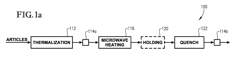
[010] FIG la is a schematic depiction of the major steps of a method for
microwave
pasteurizing or sterilizing a packaged foodstuff according to embodiments of
the present invention;
[011] FIG. lb is a schematic depiction of the major zones of a system for
microwave
pasteurizing or sterilizing a packaged foodstuff according to embodiments of
the present invention;
3
CA 03056407 2019-09-12
WO 2018/170218 PCT/US2018/022567
[012] FIG. 2 is a schematic partial side cut-away view of a microwave heating
zone
configured according to embodiments of the present invention, particularly
illustrating one
possible arrangement of the microwave heating vessel, the microwave launchers,
and the
microwave distribution system;
[013] FIG. 3 is a top isometric view of a carrier suitable for use in one or
more
embodiments of the present invention;
[014] FIG. 4 is a schematic partial side cut-away view of a microwave heating
chamber
configured according to embodiments of the present invention, particularly
illustrating possible
movements of groups of articles within the microwave heating chamber;
[015] FIG. 5 is another schematic partial side cut-away view of a microwave
heating
chamber configured according to embodiments of the present invention,
particularly illustrating
one configuration suitable for multi-pass heating;
[016] FIG. 6 is yet another schematic partial side cut-away view of a
microwave heating
chamber configured according to embodiments of the present invention,
particularly illustrating a
microwave heating zone with individual convey segments; and
[017] FIG. 7 is still another schematic partial side cut-away view of a
microwave heating
zone configured according to embodiments of the present invention,
particularly illustrating the
arrangement of a microwave heating chamber, a plurality of launchers, a
microwave generator, as
well as microwave splitters and circulator/load pairs.
DETAILED DESCRIPTION
[018] The present invention relates to methods and systems for heating a
plurality of
articles in a microwave heating system. The processes and systems as described
herein provide a
greater degree of operational flexibility and enhanced efficiency, while
permitting rapid and
uniform heating of the articles being processed. The present invention be
particularly useful for
microwave-assisted pasteurization or sterilization of packaged foodstuffs and
other similar items.
[019] In general, pasteurization involves the rapid heating of an item to a
minimum
temperature between 80 C and 100 C, while sterilization involves heating the
item to a minimum
temperature between about 100 C and about 140 C. In some cases, pasteurization
and sterilization
may take place simultaneously, or nearly simultaneously, and, as a result, the
processes and
systems described herein may be configured for both pasteurization and
sterilization.
4
CA 03056407 2019-09-12
WO 2018/170218 PCT/US2018/022567
Alternatively, the processes and systems may be configured only for
pasteurization. Examples of
suitable types of items to be pasteurized or sterilized include, but are not
limited to, packaged
foodstuffs, beverages, medical instruments and fluids, dental instruments and
fluids, veterinary
fluids, and/or pharmaceutical fluids.
[020] Embodiments of the present invention may be carried out in a variety of
different
types of microwave heating systems including, for example, those similar to
the microwave
heating systems described in U.S. Patent Application Publication No. US
2013/0240516, which is
incorporated herein by reference in its entirety. In other embodiments,
methods as described herein
may also be carried out in a microwave heating system similar to the systems
described in U.S.
Patent No. 7,119,313.
[021] Turning now to FIGS. la and lb, schematic diagrams of the main steps of
a
microwave heating process and the main elements of a microwave heating system
suitable for
pasteurizing or sterilizing articles according to embodiments of the present
invention are provided.
As used herein, the term "microwave energy" generally refers to
electromagnetic energy having a
frequency between 300 MHz and 30 GHz.
[022] As shown in FIGS. la and lb, articles introduced into the microwave
heating
system 100 are first passed through a thermalization zone 112, wherein the
articles are heated to
achieve a substantially uniform temperature. Once thermalized, the articles
may optionally be
passed through a pressure adjustment zone, shown as 114a in FIG. la, before
being introduced
into the microwave heating zone 116. In the microwave heating zone 116, the
articles may be
rapidly heated using microwave energy discharged into the heating zone 116 by
one or more
microwave launchers, as generally shown as launchers 124 in FIG. lb. The
heated articles can
then optionally be passed through a holding zone 120, wherein the articles may
be permitted to
thermally equilibrate so that the coldest portion of each article is
maintained at a temperature at or
above a predetermined target temperature (e.g., a pasteurization or
sterilization target temperature)
for a specified amount of time. Subsequently, the articles may then be passed
through a quench
zone 122, wherein the articles can be cooled to a suitable handling
temperature. Optionally, the
articles may be passed through a second pressure adjustment zone 114b before
being removed
from the system.
[023] In some cases, the thermalization, microwave heating, holding, and/or
quench
zones of the microwave system depicted in FIGS. la and lb can be defined
within a single vessel,
CA 03056407 2019-09-12
WO 2018/170218 PCT/US2018/022567
while, in other cases, one or more of these zones may be defined within one or
more separate
vessels. Additionally, in some cases, one or more of these steps can be
carried out in a vessel that
is at least partially filled with a liquid medium in which the articles being
processed can be at least
partially submerged during processing. As used herein, the term "at least
partially filled" denotes
a configuration where at least 50 percent of the volume of the specified
vessel is filled with a liquid
medium. In certain embodiments, the volume of at least one of the vessels used
in the
thermalization zone, the microwave heating zone, the holding zone, and the
quench zone can be at
least about 75 percent, at least about 90 percent, at least about 95 percent,
or 100 percent filled
with a liquid medium.
[024] When used, the liquid medium used may include any suitable type of
liquid. In
some cases, the liquid medium may have a dielectric constant greater than the
dielectric constant
of air and, in addition or the alternative, can have a dielectric constant
similar to the dielectric
constant of the articles being processed. Water (or a liquid medium comprising
water) may be
particularly suitable for systems used to heat consumable articles. The liquid
medium may also
include one or more additives, such as, for example, oils, alcohols, glycols,
and salts in order to
alter or enhance its physical properties (e.g., boiling point) of the liquid
medium at the conditions
of operation of the system.
[025] Additionally, the microwave heating system 100 may include at least one
conveyance system (not shown in FIGS. la and lb) for transporting the articles
through one or
more of the processing zones described above. Examples of suitable conveyance
systems can
include, but are not limited to, plastic or rubber belt conveyors, chain
conveyors, roller conveyors,
flexible or multi-flexing conveyors, wire mesh conveyors, bucket conveyors,
pneumatic
conveyors, screw conveyors, trough or vibrating conveyors, and combinations
thereof. Any
suitable number of individual convey lines can be used with the conveyance
system, and the
convey line or lines may be arranged in any suitable manner within the
vessels.
[026] In operation, the articles introduced into the microwave system 100
depicted in
FIGS. la and lb enter the thermalization zone 112 and are heated and/or
thermally equilibrated to
achieve a substantially uniform temperature. For example, at least about 85
percent, at least about
90 percent, at least about 95 percent, at least about 97 percent, or at least
about 99 percent of all
the articles withdrawn from the thermalization zone have a temperature within
about 5 C, within
6
CA 03056407 2019-09-12
WO 2018/170218 PCT/US2018/022567
about 2 C, or within 1 C of one another. As used herein, the terms
"thermalize" and
"thermalization" generally refer to a step of temperature equilibration or
equalization.
[027] When the thermalization zone 112 is at least partially filled with a
liquid medium,
the articles can be at least partially submerged in the liquid during the
passing. The liquid medium
in the thermalization zone 112 can be warmer or cooler than the temperature of
the articles passing
therethrough and, in some cases, can have an average bulk temperature of at
least about 30 C, at
least about 35 C, at least about 40 C, at least about 45 C, at least about 50
C, at least about 55 C,
or at least about 60 C and/or not more than about 100 C, not more than about
95 C, not more than
about 90 C, not more than about 85 C, not more than about 80 C, not more than
about 75 C, not
more than about 70 C, not more than about 65 C, or not more than about 60 C.
[028] The thermalization step can be carried out under ambient pressure or it
may be
carried out in a pressurized vessel. When pressurized, thermalization may be
performed at a
pressure of at least about 1, at least about 2, at least about 5, or at least
about 10 psig and/or not
more than about 80, not more than about 50, not more than about 40, or not
more than about 25
psig. When the thermalization zone 112 is liquid filled and pressurized, the
pressure may be in
addition to any head pressure exerted by the liquid. Articles undergoing
thermalization can have
an average residence time in the thermalization zone 112 of at least about 1
minute, at least about
minutes, at least about 10 minutes and/or not more than about 60 minutes, not
more than about
20 minutes, or not more than about 10 minutes. The articles withdrawn from the
thermalization
zone 112 can have an average temperature of at least about 20 C, at least
about 25 C, at least about
30 C, at least about 35 C and/or not more than about 90 C, not more than about
75 C, not more
than about 60 C, or not more than about 50 C.
[029] When the thermalization zone 112 and microwave heating zone 116 operate
at
substantially different pressures, the articles exiting the thermalization
zone 112 may be passed
through a pressure adjustment zone 114a before entering the microwave heating
zone 116. When
used, the pressure adjustment zone may be any zone or system configured to
transition the articles
between an area of lower pressure and an area of higher pressure. The
difference between the low
and high pressure zones may vary depending on the system and can, for example,
be at least about
1 psig, at least about 5 psig, at least about 10 psig, at least about 12 psig
and/or not more than about
75 psig, not more than about 50 psig, not more than about 40 psig, or not more
than about 35 psig.
When the quench zone 122 shown in FIGS. la and lb is operated at a different
pressure than the
7
CA 03056407 2019-09-12
WO 2018/170218 PCT/US2018/022567
microwave heating zone 116, another pressure adjustment zone may be present to
transition the
articles between the microwave heating zone 116 or hold zone 120 and quench
zone 122. In some
cases, the first pressure adjustment zone 114a can transition the articles
from a lower pressure
thermalization zone 112 to a higher pressure microwave heating zone 116, while
the second
pressure adjustment zone 114b may transition the carrier from a higher
pressure holding zone 120
(or a higher-pressure portion of the quench zone) to a lower pressure quench
zone 122, or portion
thereof.
[030] After thermalization, the articles may be introduced into the microwave
heating
zone 116 and heated using a portion of the microwave energy discharged into a
microwave heating
chamber via one or more microwave launchers, shown as 124 in FIG. lb. Various
configurations
of microwave heating systems of the present invention may employ microwave
energy having
varying frequencies, with a frequency of about 915 MHz being preferred. In
some cases, the
microwave energy discharged into the microwave heating chamber may be
polarized. In addition
to microwave energy, the microwave heating zone 116 may optionally utilize one
or more other
types of heat sources such as, for example, various conductive or convective
heating methods of
devices. However, it is generally preferred that at least about 50, at least
about 55, at least about
60, at least about 65, at least about 70, at least about 75, at least about
80, at least about 85, at least
about 90, or at least about 95 percent of the energy used to heat the articles
in the microwave
heating zone be microwave energy.
[031] One example of a microwave heating zone 316 configured for use in the
microwave
heating system described herein is shown schematically in FIG. 2. The
microwave heating zone
316 shown in FIG. 2 generally includes a microwave heating chamber 330, at
least one microwave
generator 332 for generating microwave energy, and a microwave distribution
system 334 for
directing at least a portion of the microwave energy from the generator or
generators 332 to the
microwave heating chamber 330. The system further comprises one or more
microwave launchers
322a and 322b for discharging microwave energy into the interior of the
microwave heating
chamber 330, and a convey line 340 for passing articles through the microwave
heating chamber
330.
[032] In some cases, the articles may be transported along the convey line in
groups of
two or more individual articles, while, in other cases, groups of articles may
be loaded into one or
more carriers 310, as generally depicted in FIG. 2. A description of carriers
that may be used with
8
CA 03056407 2019-09-12
WO 2018/170218 PCT/US2018/022567
the present invention is provided in U.S. Patent Application Serial No.
15/284,173, which is
incorporated herein by reference in its entirety. One example of a carrier
suitable for use in the
present invention is shown in FIG. 3. As shown in FIG. 3, the carrier 10
includes an outer frame
12, an upper support structure 14, and a lower support structure 16. The outer
frame 12 comprises
two spaced-apart side members 18a,b and two spaced-apart end members 20a,b.
The first and
second end members 20a,b may be coupled to and extend between opposite ends of
first and
second side members 18a,b to form outer frame 12. When each of side members
18a,b are longer
than the end members 20a,b, the frame may have a generally rectangular shape,
as shown FIG. 3.
[033] As also shown in FIG. 3, first and second side members 18a,b each
include
respective support projections 22a,b that are configured to engage respective
first and second
convey line support members, which are represented by dashed lines 24a and 24b
in FIG. 3. The
first and second support projections 22a,b of carrier 10 present first and
second lower support
surfaces (not shown) for supporting carrier 10 on first and second convey line
support members
24a,b. Convey line support members 24a,b may be a moving convey line element
such as, for
example, a pair of chains (not shown) located on each side of carrier 10 as it
moves through the
microwave heating zone.
[034] In some embodiments, the present invention relates to an improved method
for
heating a group of articles passing through a microwave heating chamber.
According to this
method, individual articles are transported in groups of two or more along a
convey line through
the microwave heating chamber. The convey line is configured to move the
groups of articles in
two opposite convey directions (e.g., forward and reverse) so that each of the
articles is moved
past a single microwave launcher more than once. As a result, the articles are
exposed to
microwave energy from the same launcher at least three times ¨ once during the
initial forward
pass, once during the reverse pass, and once again on the second forward pass.
This movement
can be repeated any number of times with a single launcher, and may be
repeated again with one
or more other microwave launchers within the system. This method of heating
the articles
increases the total energy discharged toward each article without requiring
the use of larger heating
chambers and more launchers. Additionally, this method provides a greater
degree of operational
flexibility by permitting various articles to be heated with different amounts
of microwave energy
by adjusting the total number of passes. Embodiments of this heating method is
described in
further detail below, with respect to Figure 4.
9
CA 03056407 2019-09-12
WO 2018/170218 PCT/US2018/022567
[035] Turning now to FIG. 4, one example of a microwave heating zone 216 is
provided.
In the example shown in FIG. 4, the microwave heating zone 216 includes a
microwave heating
chamber 230, two pairs of opposed microwave launchers (pair 224a and 224b and
pair 224c and
224d), and a convey line 240 for passing groups of articles through the
heating chamber. Other
configurations of microwave heating zones are possible including, for example,
those including
more or fewer launchers or launchers oriented in a different manner. For
example, one or more of
the launchers may be tilted at a launch tilt angle of at least 2 and/or at
least one launch opening
may be at least partially covered with a microwave-transparent window, as
described in detail in
the '516 Application. Specific examples of suitable launcher configurations,
including particular
sizes, shapes, and other features, are also described in detail in the '516
Application.
[036] Referring again to FIG. 4, a group of articles, shown with dashed lines
in FIG. 4,
may be introduced into a first zone of the microwave heating chamber 230. The
group of articles
(or any other group described herein) can include any suitable number of
individual articles
including, for example, at least 2, at least 5, at least 8, at least 10, at
least 12, at least 14, at least
16, at least 18, or at least 20 individual articles and/or not more than 100,
not more than 75, not
more than 50, not more than 40, not more than 35, or not more than 30
individual articles.
[037] As used herein with respect to the interior of the microwave heating
chamber, the
term "zone" generally refers to the space not directly under a launch opening.
A zone may be prior
to the first launcher, between two adjacent launchers, or after the last
launcher. In one embodiment
shown in FIG. 4, the first zone is located before the first pair of opposed
launchers 224a and 224b,
the second zone is located between the first pair of opposed launchers 224a
and 224b and the
second pair of opposed launchers 224c and 224d, and the third zone is located
after the second pair
of opposed launchers 224c and 224d.
[038] As used herein, the terms "first," "second," "third," and the like are
used to
describe various elements and such elements should not be limited by these
terms. These terms are
only used to distinguish one element from another and do not necessarily imply
a specific order or
even a specific element. For example, an element may be regarded as a "first"
element in the
description and a "second element" in the claims without departing from the
scope of the present
invention. Consistency is maintained within the description and each
independent claim, but such
nomenclature is not necessarily intended to be consistent therebetween.
CA 03056407 2019-09-12
WO 2018/170218 PCT/US2018/022567
[039] As shown in FIG. 4, the group of articles introduced into the first zone
of the
microwave heating chamber 230 may be moved along the convey line 240 in a
first convey
direction, shown with dashed arrow 260, toward the outlet of the microwave
heating chamber (i.e.,
the "forward" direction). As they are moved by the convey line 240, the
articles in the group pass
by at least one microwave launcher. In some cases, they may be moved past a
pair of opposed
microwave launchers, shown as launchers 224a and 224b in FIG. 4. During the
passing,
microwave energy discharged from the opening of the microwave launcher or
launchers is directed
toward the articles. When the microwave heating chamber 230 is at least
partially filled with a
liquid medium, the articles may be at least partially, or totally, submerged
in the liquid medium
during the passing.
[040] The total amount of time that the articles are moved along the convey
line 240 from
the first zone to the second zone within the interior of the microwave heating
chamber 230 and the
total amount of microwave energy discharged from one or both launchers 224a
and 224b depend,
at least in part, on the speed at which the group of articles is moved along
the convey line 240. In
some cases, the convey line speed may at least about 0.50, at least about
0.75, at least about 1, at
least about 1.5, at least about 2, or at least about 2.5 inches per minute
(in/min) and/or not more
than about 5, not more than about 4.5, not more than about 4, not more than
about 3.5, or not more
than about 3 in/min. The convey line 240 may be configured so that the line
speed can be adjusted
for different runs to alter the time and/or amount of microwave energy to
which the articles in each
separate run are exposed.
[041] Referring again to FIG. 4, once in the second zone, the group of
articles may be
subjected to a hold period, during which the articles are no longer be exposed
to microwave energy.
The articles may be permitted to thermalize during the hold period. Each hold
period may have a
total duration of at least about 5, at least about 10, at least about 15, at
least about 20, at least about
25, at least about 30, at least about 35, at least about 40, at least about
45, or at least about 50
seconds, or 1 minute and/or not more than about 10, not more than about 8, not
more than about
5, not more than about 3, not more than about 2 minutes, or not more than
about 1 minute. In some
cases, the hold period can be started by, for example, turning off the
generator or otherwise
blocking the transmission of microwave energy from the generator to the first
set of microwave
launchers. In other cases, the microwave generator may be continuously
operated and the hold
time may begin when an article moves away from the microwave field emitted by
one launcher
11
CA 03056407 2019-09-12
WO 2018/170218 PCT/US2018/022567
and may continue as the article moves along the convey line (or stops in the
subsequent zone) until
the article enters the microwave field emitted by an adjacent microwave
launcher. In such cases,
the speed of the convey line and the spacing between adjacent microwave
launchers may impact
the total duration of the hold time.
[042] After the hold period, or "dwell time," the group of articles shown in
FIG. 4 may
then be passed back from the second zone to the first zone of the microwave
heating chamber 230
by transporting the group of articles in a second convey direction opposite of
the first convey
direction, as shown by arrow 262 in FIG. 4. The second convey direction may be
toward the inlet
of the microwave heating chamber (i.e., the "reverse" direction). As the
articles are moved back
to the first zone, they pass by the same microwave launcher (or pair of
launchers 224a and 224b)
and microwave energy is again discharged from the launch opening (or openings)
toward the
articles. The convey speed used to move the group of articles back to the
first zone from the second
zone may be the same as or different than it was during the first pass.
[043] Once back in the first zone, the articles can again be subjected to a
hold period
during which they are not exposed to microwave energy. During this (or any
other) hold period,
the articles may be exposed to not more than about 25, not more than about 20,
not more than
about 15, not more than about 10, or not more than about 5 percent of the
maximum amount of
microwave energy to which the articles were exposed during passage from the
second to the first
zone. The hold period can have a total duration in the ranges provided above
and the duration may
be the same or different than the previous hold period. In some cases, one or
both of the first and
second hold periods may be omitted so that the group of articles is
continually passed back and
forth past the microwave launchers 224a and 224b.
[044] After the second hold period, when used, the group of articles may again
be
transported from the first zone to the second zone in the first convey
direction. Similar to the
previous moving steps, the articles may again pass by the same microwave
launcher or launchers
and may again be exposed to microwave energy discharged from the launch
opening. The convey
speed used to move the articles back into the second zone may be the same as
or different than the
convey speed used to transport the articles during the previous moving steps.
Once in the second
zone, the articles may again be subjected to another optional hold period of
the same or different
duration than one or both previous hold periods.
12
CA 03056407 2019-09-12
WO 2018/170218 PCT/US2018/022567
[045] After the first group of articles has moved into the second zone within
the interior
of the microwave heating chamber 230, another group of articles may be loaded
into the first zone.
This second group (not shown) may include articles of similar size, shape,
and/or type as the first
group, or one or more articles in the second group may be different. The
second group of articles
may also be loaded in a carrier. When loaded into the first zone, the first
and second groups of
articles may be spaced apart from one another along the convey line by a
distance of at least about
2, at least about 5, at least about 8, at least about 10, or at least about 12
inches, measured between
the closest points of the nearest articles in each group, or between adjacent
edges of consecutive
carriers, whichever is smallest. In some cases, adjacent groups of articles
may be spaced apart
from one another along the convey line by a minimum distance that is at least
about 50, at least
about 55, at least about 60, at least about 65, at least about 70, at least
about 75, at least about 80,
at least about 85, at least about 90, or at least about 95 percent of the
maximum dimension of the
launch opening of at least one microwave launcher that extends in the
direction parallel to the
direction along which the articles are conveyed.
[046] The second group of articles can be introduced into the first zone of
the microwave
heating chamber 230 at any suitable time. In some cases, the movement of the
second group of
articles into the first zone may be performed simultaneously with the movement
of the first group
of articles into the second zone of the microwave heating chamber 230.
Alternatively, the first
group of articles may be moved nearly entirely, or entirely, out of the first
zone of the microwave
heating chamber 230 before the step of loading the second group of articles
into the first zone of
the microwave heating chamber 230 is begun.
[047] Next, the first group of articles may be transported from the second
zone to the third
zone in the forward direction, as generally shown by arrow 264 in FIG. 4.
During this movement,
the first group of articles passes by at least one other microwave launcher,
or, as shown in FIG. 4,
a second pair of opposed microwave launchers 224c and 224d. As the articles
pass by the launcher
or launchers, microwave energy is discharged from the opening (or openings) of
the launcher (or
launchers) toward the articles. At nearly the same time, or simultaneously,
the second group of
articles may be transported along the convey line from the first zone to the
second zone of the
microwave heating chamber 230 in the forward direction and may pass by the
first microwave
launcher or set of launchers 224a and 224b. During this passing, microwave
energy discharged
from the launcher (or set of launchers) is directed toward the second group of
articles. Upon arrival
13
CA 03056407 2019-09-12
WO 2018/170218 PCT/US2018/022567
in the second and third microwave zones, respectively, the second and first
groups of articles may
be subjected to a hold period, as described previously.
[048] After the hold period, the first and second groups of articles may be
returned to
respective second and first zones of the microwave heating chamber 230 by
transporting both
groups of articles along the convey line in the reverse direction, shown by
arrows 262 and 266 in
FIG. 4. During this step, the second group of articles again passes by the
first microwave launcher
or set of launchers 224a and 224b, and the first group of articles passes by
the second microwave
launcher or set of launchers 224c and 224d, as shown in FIG. 4. Both groups of
articles are then
exposed to additional microwave energy during the passing. After another
optional hold period,
the second and first groups of articles may be returned to the respective
second and third zones of
the microwave heating chamber 230 by again moving each group of articles along
the convey line
240 in the forward direction, as shown by arrows 260 and 264. These steps may
occur
simultaneously, or the movement of one of the two groups may be delayed
relative to the other.
As the articles move into the second and third zones, the second and first
groups of articles again
pass by respective first and second launchers or pairs of launchers 224a and
224b and launchers
224c and 224d, respectively, which again discharge microwave energy toward the
articles in each
group.
[049] Once in the third zone and after an optional hold period, the first
group of articles
may be transported from the third zone into a fourth zone spaced from the
third zone by at least
one further microwave launcher (not shown) by moving the first group of
articles along the convey
line 240 in the forward direction. In this case, the first group of articles
would pass by a third
microwave launcher or pair of launchers (not shown) and would be exposed to
even more
microwave energy. Alternatively, if the second pair of launchers shown in FIG.
4 is the last pair
of launchers in the microwave heating zone, the first group of articles may be
withdrawn from the
heating chamber 230 via its outlet by moving the group of articles along the
convey line 240 in the
forward direction, and may be sent for further heating in the holding zone
(when present) or cooled
in the quench zone as shown in FIGS. la and lb.
[050] Referring again to FIG. 4, when the second group of articles is in the
second zone
of the microwave heating chamber 230, a third group of articles may be loaded
into the first zone,
as shown in FIG. 4. In some cases, the third group of articles may be loaded
into the first zone
while the second group of articles is being transported from the first zone to
the second zone and
14
CA 03056407 2019-09-12
WO 2018/170218 PCT/US2018/022567
the first group of articles is transported from the second zone to the third
zone, in a forward
direction as described previously. Alternatively, the second and first groups
of articles may be
transported into the second and third zones, respectively, before the third
group of articles is loaded
into the first zone. Thereafter, the second and third groups of articles can
proceed through the
system in a similar manner as the first and second groups of articles
described herein. Further
groups of articles may be processed in a similar manner.
[051] Although shown in FIG. 4 as including two pairs of oppositely-facing
microwave
launchers 224a and 224b and 224c and 224d, the above-described multi-pass
heating method can
be performed using a single microwave launcher. When the microwave heating
system includes
two or more microwave launchers, at least some of the launchers may be
positioned on the same
side of the microwave heating chamber. These same-side launchers may be
axially spaced from
one another along the length of the microwave heating chamber, in a direction
parallel to the
direction of travel of the carrier passing through the chamber. The microwave
system may also
include two or more same-side launchers that are laterally spaced from one
another in a direction
generally perpendicular to the direction of travel of the carriers through the
chamber. In some
embodiments, one of more same-side launchers may be disposed opposite from a
reflective surface
or only the vessel surface within the microwave heating chamber.
[052] When the microwave heating system includes two or more same-side
microwave
launchers, the launchers may be spaced apart from one another along the
direction of extension of
the heating chamber or the convey line. In some cases, when the articles are
loaded into a carrier,
adjacent same-side microwave launchers may be spaced apart from one another by
a distance that
is at least about 50, at least about 55, at least about 60, at least about 65,
at least about 70, at least
about 75, at least about 80, at least about 85, at least about 90, at least
about 95, at least about 100,
at least about 105, at least about 110, or at least about 115 percent of the
dimension of the carrier
that is parallel to the convey line when the carrier is transporting the group
of articles along the
convey line.
[053] Each microwave launcher may be configured to emit a particular amount of
microwave energy into the microwave heating chamber. For example, each
microwave launcher
may be configured to emit at least about 5, at least about 7, at least about
10, at least about 15 kW
and/or not more than about 50, not more than about 40, not more than about 30,
not more than
about 25, not more than about 20, or not more than about 17 kW. When the
system includes two
CA 03056407 2019-09-12
WO 2018/170218 PCT/US2018/022567
or more microwave launchers, each launcher may emit the same amount of energy
as one or more
other launchers, or at least one launcher may emit a different (e.g., lower or
higher) amount of
energy, as compared to at least one of the other launchers. In some cases,
each group of articles
passes by each microwave launcher at least 3, at least 5, at least 7, or even
up to 9 times. As a
result, the articles in each group is exposed to a higher "effective" number
of launchers, as
compared to the actual number of launchers within the system. This results in
more effective and
thorough heating of certain articles without the need for additional
equipment.
[054] Another example of a microwave heating zone particularly useful for
carrying out
the above-discussed multi-pass heating method is illustrated in FIG. 5. As
shown in FIG. 5, the
system generally includes a microwave heating chamber 430 and a convey line
440 for
transporting groups of articles through the heating chamber 430. The system in
FIG. 5 also
includes at least one microwave generator 432 for generating microwave energy
and at least one
microwave launcher 424 for discharging the microwave energy into the heating
chamber 430.
Additionally, the system shown in FIG. 5 includes a convey line control system
450 configured to
move the articles in a first convey direction, shown by arrow 460, and a
second, opposite convey
direction, shown by arrow 462 in FIG. 5.
[055] The convey line control system 450 permits groups of articles to move
along the
convey line and pass by the microwave launcher more than once and, in some
cases, more than
twice, as discussed in detail herein. The convey line control system 450
receives input from the
user or another control system or source, shown as input 452 in FIG. 5, and
controls the speed and
timing of the convey line 440 in order to move groups of articles through the
microwave heating
chamber 430 as discussed in detail previously.
[056] In some cases, as shown above in FIGS. 4 and 5, the microwave heating
chamber
can include a single convey line extending from the inlet to the outlet of the
chamber. In other
cases, as generally shown in FIG. 6, below, the microwave heating chamber can
include two or
more individual convey segments, shown as segments 540a, 540b, and 540c in
FIG. 6, which are
each disposed in one of the zones of the heating chamber, shown as "first,"
"second," and "third"
zones of the heating chamber 530 in FIG. 6. When the microwave heating chamber
530 includes
a single convey line, as shown, for example, in FIGS. 5 and 6, the movement of
adjacent groups
of articles may be performed simultaneously. However, when the microwave
heating chamber
16
CA 03056407 2019-09-12
WO 2018/170218 PCT/US2018/022567
includes one or more individual convey segments 540a-c, the speed and/or
timing of the movement
of various groups of articles may be different from one another.
[057] Because the groups of articles are spaced apart from one another as they
move along
the convey line in the systems shown, for example, in FIGS. 4-6, there are
periods during the
heating process during which no load is present under the microwave launchers.
Typically, this is
undesirable as it can cause problems with how the microwave energy is
distributed within the
system. For example, when no load is present between a pair of opposite
launchers, microwave
energy discharged from one launcher enters the opening of the other launcher
and can travel back
through the distribution system toward the microwave generator. This disrupts
the operation of
the remainder of the microwave energy distribution system. For example, this
type of reflected
energy will cause microwave splitters, such as those used to divide microwave
energy between
two or more launchers, to malfunction. Therefore, gaps between articles in
microwave heating
systems have traditionally been avoided in the operation of conventional
microwave heating
systems.
[058] It has unexpectedly been found that strategic placement of one or more
multi-port
circulators with dummy loads within the microwave distribution system avoids
the above problems
and permits spaced-apart groups of articles to be heated in the microwave
chamber without
disrupting the microwave energy distribution. Any suitable type of multi-port
circulator may be
used including, for example, a three-port circulator. Each microwave generator
may have a
circulator and dummy load to protect it from reflected energy. Each
circulator/load pair absorbs
reflected microwave energy to isolate the waveguide branch it is located on,
while simulating an
effective load so that the splitters and other system components continue to
function even when
the microwave launchers have no load.
[059] One example of a microwave heating zone 616 including several
circulator/load
pairs is illustrated in FIG. 7. As shown in FIG. 7, the microwave heating zone
616 includes a
microwave heating chamber 630 for heating groups of articles and a convey line
640 for
transporting the articles through the chamber. The articles may be loaded in
carriers 610, as shown
in FIG. 7. The microwave heating zone 616 shown in FIG. 7 also includes at
least one microwave
generator 632 for generating microwave energy and a microwave distribution
system 634 for
directing the microwave energy from the generator 632 to the microwave heating
chamber 630.
Microwave heating zone 616 shown in FIG. 7 also includes at least two pairs of
oppositely-facing
17
CA 03056407 2019-09-12
WO 2018/170218 PCT/US2018/022567
microwave launchers (pair of launchers 624a and 624b and pair of launchers
624c and 624d), a
plurality of waveguide branches 636, and at least three microwave splitters
638a-c for dividing the
microwave energy into a plurality of microwave energy fractions that are
ultimately discharged
from each of the launchers 624a-d.
[060] As shown in FIG. 7, the microwave heating zone 616 includes at least two
circulator/load pairs 650a and 650b positioned near one of the microwave
splitters 638a to absorb
at least a portion of the energy reflected toward the generator 632. In some
cases, at least about
35, at least about 40, at least about 45, at least about 50, at least about
55, at least about 60, at least
about 65, at least about 70, at least about 75, at least about 80, at least
about 85, or at least about
90 percent of the microwave energy discharged from one or more microwave
launchers 624a-d
may be reflected back into the system such as, for example, when the gaps
between groups of
articles (or carriers) pass under the microwave launchers 624a-d. In some
cases, the circulator/load
pairs 650a and 650b can absorb at least about 50, at least about 55, at least
about 60, at least about
65, at least about 70, at least about 75, at least about 80, at least about
85, at least about 90, at least
about 95, or at least about 97 percent of the total amount of energy reflected
into the microwave
distribution system 634 from the microwave heating chamber 630. The
circulator/load pairs can
include, for example, water loads.
[061] Although any suitable number of circulator/load pairs 650 may be used,
it has been
discovered that placing circulator/load pairs 650 in particular locations
minimizes the total number
of circulator/load pairs 650 required to protect the system without impacting
performance. More
specifically, it has been discovered that locating circulator/load pairs 650
between sets of
microwave splitters 638, as shown in FIG. 7, protects the generator 632 and
maintains operation
of the splitters 638, while minimizing the total number of circulator/load
pairs 650 needed in the
system. In some cases, the system can include not more than four, not more
than three, or not
more than two circulator/load pairs 650.
[062] Turning back to FIGS. la and lb, as the groups of articles pass through
the
microwave heating zone, the articles may be heated so that the coldest portion
of each article
achieves a target temperature. When the microwave heating system is a
sterilization or
pasteurization system, the target temperature can be a sterilization or
pasteurization target
temperature of at least about 65 C, at least about 70 C, at least about 75 C,
at least about 80 C, at
least about 85 C, at least about 90 C, at least about 95 C, at least about 100
C, at least about
18
CA 03056407 2019-09-12
WO 2018/170218 PCT/US2018/022567
105 C, at least about 110 C, at least about 115 C, at least about 120 C, at
least about 121 C, at
least about 122 C and/or not more than about 130 C, not more than about 128 C,
or not more than
about 126 C.
[063] When the microwave heating zone 116 includes a liquid-filled microwave
heating
chamber, the average bulk temperature of the liquid in the microwave heating
chamber may vary
and, in some cases, can depend on the amount of microwave energy discharged
into the microwave
heating chamber. The average bulk temperature of the liquid in the microwave
heating chamber
can be at least about 70 C, at least about 75 C, at least about 80 C, at least
about 85 C, at least
about 90 C, at least about 95 C, at least about 100 C, at least about 105 C,
at least about 110 C,
at least about 115 C, or at least about 120 C and/or not more than about 135 ,
not more than about
132 C, not more than about 130 C, not more than about 127 C, or not more than
about 125 C.
[064] As the articles pass through the microwave heating zone 116, they may be
heated
to the target temperature in a relatively short period of time, which can help
minimize any damage
or thermal degradation of the articles. For example, the average residence
time of each article
passing through the microwave heating zone 116 can be at least about 5
seconds, at least about 20
seconds, at least about 60 seconds and/or not more than about 10 minutes, not
more than about 8
minutes, not more than about 5 minutes, not more than about 3 minutes, not
more than about 2
minutes, or not more than about 1 minute. The minimum temperature of the
articles heated in the
microwave heating zone 116 can increase by at least about 5 C, at least about
10 C, at least about
15 C, at least about 20 C, at least about 30 C, at least about 40 C, at least
about 50 C, at least
about 75 C and/or not more than about 150 C, not more than about 125 C, or not
more than about
100 C.
[065] In some embodiments, the microwave heating zone (or heating chamber
therein)
can be operated at approximately ambient pressure. Alternatively, microwave
heating zone 116
may include a pressurized microwave chamber that operates at a pressure that
is at least 5 psig, at
least about 10 psig, at least about 15 psig, or at least about 17 psig and/or
not more than about 80
psig, not more than about 60 psig, not more than about 50 psig, or not more
than about 40 psig
above ambient pressure. As used herein, the term "ambient" pressure refers to
the pressure exerted
by the fluid in the microwave heating chamber without the influence of
external pressurization
devices.
19
CA 03056407 2019-09-12
WO 2018/170218 PCT/US2018/022567
[066] As shown in FIGS. la and lb, upon exiting the microwave heating zone
116, the
articles may be passed to an optional holding zone 120, wherein the
temperature of the articles can
be maintained at or above a certain target temperature for a predetermined
period of time. For
example, in the holding zone 120, the temperature of the coldest part of the
article can be held at
a temperature at or above a predetermined minimum temperature of at least
about 70 C, at least
about 75 C, at least about 80 C, at least about 85 C, at least about 90 C, at
least about 95 C, at
least about 100 C, at least about 105 C, at least about 110 C, at least about
115 C, or at least about
120 C, at least about 121 C, at least about 122 C and/or not more than about
130 C, not more
than about 128 C, or not more than about 126 C, for a period of time (or
"holding period") of at
least about 1 minute, at least about 2 minutes, or at least about 4 minutes
and/or not more than
about 20 minutes, not more than about 16 minutes, or not more than about 10
minutes.
[067] Once the heated articles, which may be sufficiently pasteurized or
sterilized, exit
the holding zone 120, when present, the articles may then be introduced into a
quench zone 122,
wherein they are cooled as rapidly as possible via submersion in a cooled
fluid. The quench zone
122 may reduce the external surface temperature of the articles by at least
about 30 C, at least
about 40 C, at least about 50 C and/or not more than about 100 C, not more
than about 75 C, or
not more than about 50 C in a time period of at least about 1 minute, at least
about 2 minutes, at
least about 3 minutes and/or not more than about 10 minutes, not more than
about 8 minutes, or
not more than about 6 minutes. Any suitable fluid may be used in the quench
zone 122 and, in
some cases, the fluid may include a liquid similar to, or different than, the
liquid used in the
microwave heating zone 116 and/or the holding zone 120, if present. When
removed from the
quench zone 122, the cooled articles can have a temperature of at least about
20 C, at least about
25 C, at least about 30 C and/or not more than about 70 C, not more than about
60 C, or not more
than about 50 C. Once removed from the quench zone 122, the cooled, treated
articles can then
be removed from the microwave heating system for subsequent storage and/or
use.
[068] Microwave heating systems of the present invention can be commercial-
scale
heating systems capable of processing a large volume of articles in a
relatively short time. In
contrast to conventional retorts and other small-scale systems that utilize
microwave energy to
heat a plurality of articles, microwave heating systems as described herein
can be configured to
achieve an overall production rate of at least about 5 packages per minute, at
least about 10
packages per minute, at least about 15 packages per minute per convey line, at
least about 20
CA 03056407 2019-09-12
WO 2018/170218 PCT/US2018/022567
packages per minute per convey line, at least about 25 packages per minute per
convey line, or at
least about 30 packages per minute per convey line, measured as described in
the '516 Application.
Alternatively, or in addition, the overall production rate can be not more
than about 200, not more
than about 150, not more than about 100, not more than about 75, not more than
about 50, not
more than about 35, or not more than about 30 packages per minute.
DEFINITIONS
[069] As used herein, the terms "comprising," "comprises," and "comprise" are
open-
ended transition terms used to transition from a subject recited before the
term to one or more
elements recited after the term, where the element or elements listed after
the transition term are
not necessarily the only elements that make up the subject.
[070] As used herein, the terms "including," "includes," and "include" have
the same
open-ended meaning as "comprising," "comprises," and "comprise."
[071] As used herein, the terms "having," "has," and "have" have the same open-
ended
meaning as "comprising," "comprises," and "comprise."
[072] As used herein, the terms "containing," "contains," and "contain" have
the same
open-ended meaning as "comprising," "comprises," and "comprise."
[073] As used herein, the terms "a," "an," "the," and "said" mean one or more.
[074] As used herein, the term "and/or," when used in a list of two or more
items, means
that any one of the listed items can be employed by itself or any combination
of two or more of
the listed items can be employed. For example, if a composition is described
as containing
components A, B, and/or C, the composition can contain A alone; B alone; C
alone; A and B in
combination; A and C in combination; B and C in combination; or A, B, and C in
combination.
[075] The preferred forms of the invention described above are to be used as
illustration
only, and should not be used in a limiting sense to interpret the scope of the
present invention.
Obvious modifications to the exemplary one embodiment, set forth above, could
be readily made
by those skilled in the art without departing from the spirit of the present
invention.
[076] The inventors hereby state their intent to rely on the Doctrine of
Equivalents to
determine and assess the reasonably fair scope of the present invention as
pertains to any apparatus
not materially departing from but outside the literal scope of the invention
as set forth in the
following claims.
21