Note: Descriptions are shown in the official language in which they were submitted.
CA 03056539 2019-09-13
WO 2018/203124
PCT/IB2018/000365
FOUR-POINT CAB SUSPENSION SYSTEM
TECHNICAL FIELD
[0001] The present disclosure is generally related to vehicle cab
suspension
systems.
BACKGROUND
[0002] Current cab suspension systems suffer from reduced comfort for
the
operator due in large part to high roll stiffness. Roll refers to side-to-side
movement of the cab, or similarly, load transfer of the cab toward the
outside.
Roll stiffness refers to the torque applied by the suspension system as the
cab
rolls due to rotational force applied to the cab (e.g., as measured in pound-
feet
per degree of roll). For instance, 2-point suspension systems possess high
roll
stiffness due to rubber mounts in the front between the cab and the frame, and
4-point suspension systems have high roll stiffness due to an anti-roll bar
added
to control the roll stiffness given the inability of current 4-point
suspension
systems to adequately control cab roll without the anti-roll bar. Indeed, high
roll
stiffness occurs regardless of whether rubber mounts are placed in the front
or
the back of the cab.
BRIEF DESCRIPTION OF THE DRAWINGS
[0003] Many aspects of certain embodiments of 4-point cab suspension
systems
and methods can be better understood with reference to the following drawings.
The components in the drawings are not necessarily to scale, emphasis instead
CONFIRMATION COPY
CA 03056539 2019-09-13
WO 2018/203124
PCT/IB2018/000365
methods. Moreover, in the drawings, like reference numerals designate
corresponding parts throughout the several views.
[0004] FIG. 1 is a schematic diagram that illustrates, in front perspective
view, an
example vehicle in which an embodiment of a 4-point cab suspension system
may be implemented.
[0005] FIG. 2 is a schematic diagram that illustrates, in fragmentary, side
elevation view, an embodiment of a 4-point cab suspension system.
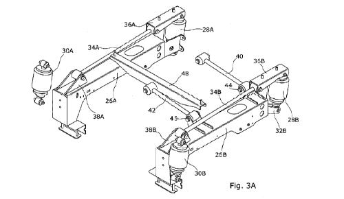
[0006] FIG. 3A is a schematic diagram that illustrates, in fragmentary,
rear-
perspective view, select components of an embodiment of a 4-point cab
suspension system.
[0007] FIG. 3B is a schematic diagram that illustrates, in fragmentary,
front-
perspective view, select components of an embodiment of a 4-point cab
suspension system.
[0008] FIG. 3C is a schematic diagram that illustrates, in fragmentary,
front
bottom perspective view, select components of an embodiment of a 4-point cab
suspension system.
[0009] FIG. 4 is a flow diagram that illustrates an embodiment of an
example 4-
point cab suspension method.
2
CA 03056539 2019-09-13
WO 2018/203124
PCT/IB2018/000365
DESCRIPTION OF EXAMPLE EMBODIMENTS
Overview
[0010] In one embodiment, a suspension system for a vehicle cab, the
suspension system comprising: a structural assembly; a cab mounted to the
structural assembly; and plural suspension units arranged between the cab and
the structural assembly, the plural suspension units comprising, fore and aft,
a
first pair of suspension units and a second pair of suspension units, wherein
a
lateral distance between the second pair of suspension units is greater than a
lateral distance between the first pair of suspension units.
Detailed Description
[0011] Certain embodiments of a four-point (hereinafter, 4-point) cab
suspension system and method are disclosed that comprise a pair of rear
suspension units spaced wider apart than a pair of front suspension units,
which
improves cab roll control over a 4-point suspension system that mounts the
suspension units according to a square or rectangle and over 2-point systems.
The embodiments described below are in the context of a vehicle embodied as
an agricultural vehicle, and in particular, a self-propelled windrower, with
the
understanding that cab suspension systems for other vehicles may be used in
some embodiments.
[0012] Digressing briefly, some vehicles operate under conditions that
demand sufficient cab roll control. For instance, in the agricultural
equipment
industry, agricultural vehicles such as windrowers generally have a wide track
3
CA 03056539 2019-09-13
WO 2018/203124
PCT/IB2018/000365
agricultural machines. When the left or right wheel encounters obstacles in
the
field, such as gopher holes or other field obstacles or terrain
discontinuities,
there is a tendency toward cab roll that needs sufficient roll control to
enable
operator comfort, as excessive rolling motion is generally considered a
discomforting sensation to people in general (e.g., particularly when compared
to
the heave (up-down) motion of the vehicle). Conventional 2-point windrower cab
suspensions use front isolation mounts (hereinafter, simply mounts or rubber
mounts, which have a total deformation that is measured in millimeters), which
are applicable for control of high-frequency (e.g., greater than approximately
10-
12 Hz), small displacement disturbances or vibrations, such as those that are
generated by the machine (windrower) or machine components (e.g., hydraulic
pumps, the engine, etc.). In other words, isolation mounts are too stiff to
attenuate low frequency forces. When the windrower encounters a disturbance
on only one side (e.g., a gopher mound), the entire windrower rolls as the
tire
travels up and over the mound. That is, with the high roll stiffness of
isolation
mounts, the cab rolls with the vehicle. The terrain, on the other hand, is a
source
of the low frequency vibrations (e.g., the terrain causes the low frequency
vibrations experienced by an operator in the cab, such as those corresponding
to
cab roll), which suspension units (construed herein as low frequency
suspension
units, including air spring or coil over shock absorber in an integrated or
physically separate packages or units) are intended to address. Note that
total
travel of suspension units, unlike isolation mounts, is measured in inches
under
4
CA 03056539 2019-09-13
WO 2018/203124
PCT/IB2018/000365
where the suspension units are disposed between the frame and the cab in a
square or rectangular arrangement, roll control is achieved with a roll bar,
which
likewise results in discomfort for the operator due to high roll stiffness.
[0013] In contrast, certain embodiments of a 4-point cab suspension
system
may improve ride comfort for the operator through the use of suspension units
(i.e., low frequency suspension units) mounted beneath the cab in a mounting
arrangement where the rear pair of suspension units are spaced wider apart
than
the front pair of suspension units. In some embodiments, these suspension
units are passive (e.g., not electronically or manually adjustable in the
field).
Such an arrangement of low-frequency type, passive suspension units enables
the cab motion to more closely achieve one goal of trying to keep the cab
approximately level as the windrower travels over terrain while enabling the
omission of an anti-roll bar, improving comfort for the operator over
conventional
cab suspension systems.
[0014] Having summarized certain features of a 4-point cab suspension
system
of the present disclosure, reference will now be made in detail to the
description
of a 4-point cab suspension system as illustrated in the drawings. While an
example 4-point cab suspension system will be described in connection with
these drawings, there is no intent to limit it to the embodiment or
embodiments
disclosed herein. For instance, as indicated above, certain embodiments of a 4-
point cab suspension system are described in the context of its use in an
agricultural vehicle, and in particular, a self-propelled windrower. However,
in
CA 03056539 2019-09-13
WO 2018/203124
PCT/IB2018/000365
agricultural vehicles, or in vehicles used in other industries, including
mining,
construction, military, government, etc. Further, although the description
identifies or describes specifics of one or more embodiments, such specifics
are
not necessarily part of every embodiment, nor are all of any various stated
advantages necessarily associated with a single embodiment. On the contrary,
the intent is to cover all alternatives, modifications and equivalents
included
within the scope of the disclosure as defined by the appended claims. Further,
it
should be appreciated in the context of the present disclosure that the claims
are
not ---- necessarily limited to the particular embodiments set out in the
description.
[0015]
Note that references hereinafter made to certain directions, such as, for
example, "front", "rear", "left" and "right", are made as viewed from the rear
of
the vehicle (e.g., windrower) looking forwardly. The terms fore and aft and
transverse, as used herein, are referenced to the longitudinal centerline of
the
windrower chassis as the windrower travels in a forward direction. Also, note
that reference to a passive suspension system refers to the fact that there is
no
manual or computer-assisted change in dampening in the field. Passive is
distinct from semi-active or active type control. Semi-active type control
involves
monitoring movement of the cab and reacting by changing the dampening rates
with respect to position in dampener stroke and rate of change. Active type
control refers to use of actuators (e.g., in a dampening component) to control
motion in order for the cab to remain stationary while the chassis moves
underneath the cab. Further, note that reference to having a wider lateral
6
CA 03056539 2019-09-13
WO 2018/203124
PCT/IB2018/000365
example rear width-to-front width ratio of approximately 1.3. In some
embodiments, the rear width-to-front width ratio may be greater, or slightly
less in
some embodiments.
[0016]
Referring now to FIG. 1, shown is an example vehicle, and in particular, a
self-propelled windrower 10, in which an embodiment of a 4-point cab
suspension system 12 may be implemented. One having ordinary skill in the art
should appreciate in the context of the present disclosure that the example
windrower 10 depicted in FIG. 1 is of one type of self-propelled design, and
that
other windrower designs or other types of vehicles may be used and hence are
contemplated to be within the scope of the disclosure. The windrower 10 is
operable to mow and collect standing crop in the field, condition the cut
material
(e.g., using one or more pairs of conditioner rolls) to improve its drying
characteristics, and then return the conditioned material to the field in a
windrow
or swath. The windrower 10 may include a chassis or frame 14 supported by
wheels 16 (although tracks may be used in some embodiments, or other
configurations in the number and/or arrangement of wheels may be used in
some embodiments) for movement across a field to be harvested. The chassis
14 supports a cab 18, within which an operator may control certain operations
of
the windrower 10, and a rearwardly spaced compartment 20 housing a power
source (not shown) such as an internal combustion engine. The chassis 14 also
supports a ground drive system that, in one embodiment, when powered by the
engine, causes differential rotation of the wheels (e.g., increasing the speed
of
7
CA 03056539 2019-09-13
WO 2018/203124
PCT/IB2018/000365
path steering mechanism as is known in the art. In some embodiments, other
mechanisms for enabling navigation and/or traversal of the field may be used.
[0017] A
coupled working implement, depicted in FIG. 1 as a harvesting header
22, is supported on the front of the chassis 14 in a manner understood by
those
skilled in the art. The header 22 may be configured as a modular unit and
consequently may be disconnected for removal from the chassis 14. As is also
known in the art, the header 22 has a laterally extending crop cutting
assembly
24 in the form of a low profile, rotary style cutter bed located adjacent the
front of
the header 22 for severing crop from the ground as the windrower 10 navigates
across a surface in the field. However, one skilled in the art will understand
that
other types of crop cutting assemblies 24, such as sickle style cutter beds,
may
also be used in some embodiments.
[0018] The
windrower 10 also includes the 4-point cab suspension system 12,
which includes plural suspension units that are disposed between the cab 18
and
the chassis 14 to improve ride comfort for the operator, as explained further
below. For air spring-based suspension units, additional components may
include a source of air (e.g., compressor) as is known to those having
ordinary
skill in the art.
[0019]
During a harvesting operation, the windrower 10 moves forward through
the field with the header 22 lowered to a working height. Ground conditions
(e.g.,
moist ground, soft ground, etc.), including ground surface topology (e.g.,
bumpy
terrain, smooth terrain, obstacles, etc.), encountered by the tires, impose
low
8
CA 03056539 2019-09-13
WO 2018/203124
PCT/IB2018/000365
the ride. The 4-point cab suspension system 12 ensures a comfortable ride for
the operator despite the condition of the terrain the windrower 10 encounters.
[0020]
Attention is now directed to FIG. 2, which illustrates an embodiment of the
4-point cab suspension system 12. Certain known components, which would be
readily apparent to one having ordinary skill in the art, are omitted from
FIG. 2 to
avoid obfuscating relevant components of the 4-point cab suspension system 12.
In one embodiment, the 4-point cab suspension system 12 comprises the cab
18, a sub-frame 26 (e.g., in one embodiment comprising at least two pieces,
one
shown in FIG. 2 and denoted 26A) to which the cab 18 is mounted, a pair of
front
suspension units 28 (one shown in FIG. 2, denoted as suspension unit 28A)
coupled to the front of the sub-frame 26, and a pair of rear suspension units
30
(one shown in FIG. 2, denoted as suspension unit 30A) coupled to the chassis
14 (not depicted in FIG. 2). The sub-frame 26 and the chassis or frame 14 of
the
windrower 10 (FIG. 1) are collectively referred to herein as a structural
assembly.
It should be appreciated by one having ordinary skill in the art that, though
the
sub-frame 26 is shown disposed between the cab 18 and the chassis 14, in
some embodiments, the sub-frame 26 may be omitted (and hence both the front
pair of suspension units 28 and the rear pair of suspension units 30 may both
be
attached directly to the chassis 14), as long as the lateral distance between
the
rear pair of suspension units 30 is greater than the lateral distance between
the
front pair of suspension units 28. In some embodiments, other variations in
attachment connection between the cab 18 and the chassis 14 (e.g., using one
9
CA 03056539 2019-09-13
WO 2018/203124
PCT/IB2018/000365
weld, bolts, tacks, etc. to the front suspension units 28 or cab 18) are
contemplated, as long as the lateral distance between the rear pair of
suspension units 30 is greater than the lateral distance between the front
pair of
suspension units 28. The suspension units 28, 30 provide for a passive, 4-
point
suspension system. In one embodiment, the suspension units 28, 30 are each
configured as integrated air spring over damper (shock absorber) types of
suspension units. The air spring may comprise integrated (or external in some
embodiments) leveling valves that add or release air from the air springs, as
is
known. In some embodiments, the suspension units 28, 30 are each configured
as integrated coil over shock absorber types of suspension units. In some
embodiments, the suspension units 28, 30 are each configured as two physically
separate components that collectively function together, wherein one component
comprises either an air spring or coil spring and the other component
comprises
a shock absorber. In some embodiments, there may be a mixture of different
types of the aforementioned suspension units 28, 30.
[0021]
With continued reference to FIG. 2, attention is directed to FIGS. 3A-3C,
which illustrate various views of select portions of the 4-point cab
suspension
system 12 shown in FIG. 2. Each of the front pair of suspension units 28 is
respectively attached at one end (lower end) of the suspension unit 28 to a
bracket 32 (e.g., 32A, 32B) extending forwardly from the sub-frame 26 (e.g.,
26A, 26B), the bracket 32 affixed (attached and affixed used interchangeably
herein) to the sub-frame 26 using known attachment mechanisms (e.g., weld,
CA 03056539 2019-09-13
WO 2018/203124
PCT/IB2018/000365
suspension units 28 is coupled to the cab 18 (proximal the forward portion of
the
cab 18) via a respective longitudinal bar or member 34 (e.g., 34A, 34B).
[0022] In
one embodiment, one end (the forward end) of each longitudinal
member 34 is attached to a front mount bracket 36 (e.g., 36A, 36B) that
couples
the forward end of the longitudinal member 34 to the cab 18. In one
embodiment, the front mount bracket 36 is of a generally rectangular, U-shaped
configuration, with the top surface of the front mount bracket 36 affixed to a
bottom surface (or intervening structure) of the cab 18, and at one end
(rearward
end), affixed (e.g., bolted) between the U-shaped walls of the front mount
bracket 36 to the forward end (e.g., ring or trunnion mount) of the
longitudinal
member 34, and at the other (forward) end of the front mount bracket 36,
affixed
(e.g., bolted) between the U-shaped walls of the front mount bracket 36 to a
top
mounting end (e.g., ring or trunnion mount) of the front suspension unit 28.
The
other end (rearward end) of each longitudinal member 34 is pivotably coupled
to
a rear mount bracket 38 (e.g., 38A, 38B). In one embodiment, the rear mount
bracket 38 is configured as a trunnion, with upright, generally triangular
side
walls to which the rearward end (e.g., ring or trunnion mount) of the
longitudinal
member 34 is affixed (e.g., bolted) and free to pivot. The rear mount bracket
38
is affixed (e.g., welded, tracked, bolted, etc.) to a top surface of the sub-
frame
26.
[0023]
Coupled to one of the sub-frames (sub-frame 26B), fore and aft, are
respective transverse members 40 and 42, which in one embodiment are
11
CA 03056539 2019-09-13
WO 2018/203124
PCT/IB2018/000365
transverse to the sub-frame 26B (and beneath a portion of the cab 18,
extending
to approximately the longitudinal midline of the cab 18). In some embodiments,
the transverse members 40 and 42 may be coupled to the opposing sub-frame
26A instead. In one embodiment, the transverse members 40 and 42 are of
equal length or approximately equal length (e.g., enabling concurrent movement
in an arc as the cab 18 moves up and down), and are each pivotably coupled to
fore and aft mount brackets 44 and 46, respectively. In one embodiment, the
mount brackets 44 and 46 may be configured as trunnions affixed (e.g., welded,
tacked, etc.) to the top and internal side surfaces of the sub-frame 26B. The
mount brackets 44 and 46 are respectively mounted proximal to the rearward
end of the brackets 32 and forward of the rear mount brackets 38. The
transverse member 40 is attached at the end opposite the pivotal attachment to
the underside surface of the cab 18, approximately at the longitudinal midline
of
the cab 18. For instance, the transverse member 40 may be attached to a U-
shaped bracket, in somewhat similar manner to the attachment mechanism and
structure of the structural member 48, which in turn is attached to the
underside
of the cab 18 (a portion of the U-shaped bracket is shown in FIG. 2). The
transverse member 42 is attached at the end opposite of the pivotal attachment
to a structural member 48, the structural member 48 attached at one end to the
top surface of the sub-frame 26A. The structural member 48 is of a generally U-
shaped configuration, with the top surface attached to the underside of the
cab
18 and the non-pivotal side of the transverse member 42 attached to the
12
CA 03056539 2019-09-13
WO 2018/203124
PCT/IB2018/000365
some structural support for the transverse member 42 to be affixed to (e.g.,
bolted through a ring or trunnion of the transverse member 42, though other
mechanism to secure the transverse member 42 to the structural member 48
may be used).
[0024] The
longitudinal members 34 and the transverse members 40, 42
effectively secure the cab 18 to the structural assembly, and more
specifically,
enable the cab 18 some freedom of movement (e.g., up-down, pitch, roll) while
holding the cab 18 in position. The transverse members 40, 42 help prevent
movement of the cab 18 side-to-side, and the transverse member 40 further
provides some resistance to twisting motion of the cab 18. The longitudinal
members 34 support the cab 18 fore and aft and help prevent twisting movement
of the cab 18.
[0025] As
described above, the rear suspension units 30 are spaced farther apart
from each other (referring to the lateral distance between each unit of the
rear
pair 30) than the front suspension units 28 (again, referring to the lateral
distance
between each unit of the front pair 28), which provides for improved roll
control
versus conventional 2-point or 4-point suspension systems and renders
unnecessary the need for an anti-roll bar (which for conventional 4-point
suspension systems, is generally arranged with two connection points to the
chassis and two connection points to the underside of the cab, and is
generally
used to convert side-side movement to up-down movement). In
one
embodiment, the rear pair of suspension units 30 are spaced apart
13
CA 03056539 2019-09-13
WO 2018/203124
PCT/IB2018/000365
spaced apart approximately 1067 mm. These dimensions are one example, and
in some embodiments, other dimensions (of the same or different ratio) may be
used. In effect, there is improved comfort through the improvement in roll
control
and omission of the anti-roll bar, and reduced assembly and material.
[0026] It
should be appreciated by one having ordinary skill in the art, in the
context of the disclosure, that particular details of the assembly and/or
construction of the 4-point cab suspension system 12 is illustrative of one
embodiment, and that variations to the above description may be implemented
while preserving the difference in lateral spacing between the rear suspension
units 30 relative to the lateral distance between the front suspension units
28
and hence are contemplated to be within the scope of the disclosure.
[0027] In
view of the above description, it should be appreciated that one
embodiment of a 4-point cab suspension method 50, depicted in FIG. 4,
comprises navigating a vehicle along a surface (52); and controlling cab roll
of
the vehicle, as the vehicle navigates along the surface, with plural
suspension
units, the plural suspension units comprising, fore and aft, a first pair of
suspension units and a second pair of suspension units, wherein a lateral
distance between the second pair of suspension units is greater than a lateral
distance between the first pair of suspension units (54).
[0028] Any
process descriptions or blocks in flow diagrams should be understood
as representing steps in a process, and alternate implementations are included
14
CA 03056539 2019-09-13
WO 2018/203124
PCT/IB2018/000365
understood by those reasonably skilled in the art of the present disclosure.
[0029] In
this description, references to "one embodiment", "an embodiment", or
"embodiments" mean that the feature or features being referred to are included
in at least one embodiment of the technology. Separate references to "one
embodiment", "an embodiment", or "embodiments" in this description do not
necessarily refer to the same embodiment and are also not mutually exclusive
unless so stated and/or except as will be readily apparent to those skilled in
the
art from the description. For example, a feature, structure, act, etc.
described in
one embodiment may also be included in other embodiments, but is not
necessarily included. Thus, the present technology can include a variety of
combinations and/or integrations of the embodiments described herein.
Although the systems and methods have been described with reference to the
example embodiments illustrated in the attached drawing figures, it is noted
that
equivalents may be employed and substitutions made herein without departing
from the scope of the disclosure as protected by the following claims.