Note: Descriptions are shown in the official language in which they were submitted.
MULTI-USE DESK-CABINET
FIELD OF THE INVENTION
The present invention relates to a piece of furniture, and more particularly
to a space saving
multi-use desk-cabinet.
BACKGROUND OF THE INVENTION
In many urban and suburban areas, living space is a premium. Limited floor
space in apartments,
homes, and other living spaces can make it difficult to properly furnish a
space for one or more
desired purposes. The limited floor space makes it difficult to provide
sufficient space for storing
items such as, for example, childrens' toys, books, etc., as well as
sufficient desk space for
playing or doing homework. The same problem arises for various other home
activities requiring
space for storing items as well as for working such as, for example, a
computer space,
reading/learning space, home office space, and art and crafts space.
There are various pieces of furniture available for use in situations of
limited floor space such as,
for example, wall desks and secretary desks. Unfortunately, they either
provide very limited or
no storage space or very limited desk size.
It is desirable to provide a multi-use desk-cabinet that provides sufficient
storage space, as well
as sufficient desk space.
It is also desirable to provide a multi-use desk-cabinet with a desk plate
that is pivotally and
slidably movable from a substantially vertical position to a horizontal
position.
It is also desirable to provide a multi-use desk-cabinet wherein a substantial
portion of the desk
plate is placed inside the cabinet when the desk plate is in the horizontal
position.
It is also desirable to provide a multi-use desk-cabinet wherein the desk
plate is adapted for use
as a white board when the desk plate is in the vertical position.
Page 1
CA 3056566 2019-09-24
SUMMARY OF THE INVENTION
Accordingly, one object of the present invention is to provide a multi-use
desk-cabinet that
provides sufficient storage space, as well as sufficient desk space.
Another object of the present invention is to provide a multi-use desk-cabinet
with a desk plate
that is pivotally and slidably movable from a substantially vertical position
to a horizontal
position.
Another object of the present invention is to provide a multi-use desk-cabinet
wherein a
substantial portion of the desk plate is placed inside the cabinet when the
desk plate is in the
horizontal position.
Another object of the present invention is to provide a multi-use desk-cabinet
wherein the desk
plate is adapted for use as a white board when the desk plate is in the
vertical position.
According to one aspect of the present invention, there is provided a multi-
use desk-cabinet. The
multi-use desk-cabinet comprises a rear cabinet wall having a left and a right
side cabinet wall
mounted thereto. A desk plate is slidably and pivotally movable mounted to
each of the left and
the right side cabinet wall such that the desk plate is movable from a
substantially vertical
position in proximity to a front end of the left and the right side cabinet
wall to a substantially
horizontal position such that a rear end of the desk plate is placed in close
proximity to the rear
cabinet wall.
According to the aspect of the present invention, there is provided a multi-
use desk-cabinet. The
multi-use desk-cabinet comprises a rear cabinet wall having a left and a right
side cabinet wall
mounted thereto. A desk plate is slidably and pivotally movable mounted to
each of the left and
the right side cabinet wall such that the desk plate is movable from a
substantially vertical
position in proximity to a front end of the left and the right side cabinet
wall to a substantially
horizontal position such that a rear end of the desk plate is placed in close
proximity to the rear
cabinet wall. A left and right side guiding groove is disposed in each of the
left and the right side
Page 2
CA 3056566 2019-09-24
cabinet wall, respectively and a left and right side guiding pin are mounted
to a rear portion of
the desk plate. Each of the left and right side guiding pin is slidably and
pivotally movable
accommodated in the respective left and right side guiding groove.
According to the aspect of the present invention, there is provided a multi-
use desk-cabinet. The
multi-use desk-cabinet comprises a rear cabinet wall having a left and a right
side cabinet wall
mounted thereto. A desk plate is slidably and pivotally movable mounted to
each of the left and
the right side cabinet wall such that the desk plate is movable from a
substantially vertical
position in proximity to a front end of the left and the right side cabinet
wall to a substantially
horizontal position such that a rear end of the desk plate is placed in close
proximity to the rear
cabinet wall. The multi-use desk-cabinet further comprises a desk enclosure
top wall and a desk
enclosure bottom wall. The desk enclosure top wall and the desk enclosure
bottom wall are
mounted to the rear cabinet wall and the left and the right side cabinet wall
such that the same
form a desk enclosure in concert with the desk plate when placed in the
substantially vertical
position.
The advantage of the present invention is that it provides a multi-use desk-
cabinet that provides
sufficient storage space, as well as sufficient desk space.
A further advantage of the present invention is that it provides a multi-use
desk-cabinet with a
desk plate that is pivotally and slidably movable from a substantially
vertical position to a
horizontal position.
A further advantage of the present invention is that it provides a multi-use
desk-cabinet wherein
a substantial portion of the desk plate is placed inside the cabinet when the
desk plate is in the
horizontal position.
A further advantage of the present invention is that it provides a multi-use
desk-cabinet wherein
the desk plate is adapted for use as a white board when the desk plate is in
the vertical position.
BRIEF DESCRIPTION OF THE DRAWINGS
Page 3
CA 3056566 2019-09-24
A preferred embodiment of the present invention is described below with
reference to the
accompanying drawings, in which:
Figures 1 and 2 are simplified block diagrams illustrating in front
perspective views a
multi-use desk-cabinet according to the preferred embodiment of the invention
with the
desk plate being in the vertical position and in the horizontal position,
respectively;
Figure 3 is a simplified block diagram illustrating in a bottom view the desk
plate of the
multi-use desk-cabinet according to the preferred embodiment of the invention;
Figure 4 is a simplified block diagram illustrating in a cross sectional view
the multi-use
desk-cabinet according to the preferred embodiment of the invention;
Figure 5 is a simplified block diagram illustrating in a cross sectional view
the movement
of the desk plate of the multi-use desk-cabinet according to the preferred
embodiment of
the invention; and,
Figures 6 and 7 are simplified block diagrams illustrating in cross sectional
views a detail
of the multi-use desk-cabinet according to the preferred embodiment of the
invention
without and with the desk plate, respectively.
DESCRIPTION OF THE PREFERRED EMBODIMENT
Unless defined otherwise, all technical and scientific terms used herein have
the same meaning
as commonly understood by one of ordinary skill in the art to which the
invention belongs.
Although any methods and materials similar or equivalent to those described
herein can be used
in the practice or testing of the present invention, the preferred methods and
materials are now
described.
Referring to Figures lto 7 a multi-use desk cabinet 100 according to a
preferred embodiment of
the invention is provided. The multi-use desk cabinet 100 comprises rear
cabinet wall 112
having left and right side cabinet walls 102 mounted thereto. Desk plate 104
is slidably and
Page 4
CA 3056566 2019-09-24
pivotally movable mounted to each of the left and the right side cabinet wall
102 such that the
desk plate 104 is movable from a substantially vertical position in proximity
to a front end 102.F
of the left and the right side cabinet wall 102, as illustrated in Figures 1
and 4, to a substantially
horizontal position such that a rear end 104.2 of the desk plate 104 is placed
in close proximity
to the rear cabinet wall 112, as illustrated in Figure 2 and 4. The multi-use
desk-cabinet 100
further comprises desk enclosure top wall 108 and desk enclosure bottom wall
110. The desk
enclosure top wall 108 and the desk enclosure bottom wall 110 are mounted to
the rear cabinet
wall 112 and the left and the right side cabinet wall 102 such that the same
form a closed desk
enclosure 128 in concert with the desk plate 104 when the same is placed in
the substantially
vertical position (I).
Movement of the desk plate 104 from the vertical position (I) to the
horizontal position (II) is
enabled by providing left and right side guiding pins 103 mounted to a rear
portion in proximity
to the rear end 104.2 of the desk plate104, as illustrated in Figure 3, and
left and right side
guiding grooves 134 disposed in each of the left and the right side cabinet
wall 102, respectively.
Each of the left and right side guiding pins 130 is slidably and pivotally
movable accommodated
in the respective left and right side guiding groove 134, as illustrated in
Figure 4. As illustrated
in Figure 5, the desk plate 104 is moved from the vertical position (I) into
the horizontal position
(II) by:
first rotating the desk plate 104 (I) about the guiding pins when in the
vertical position 130 (I), as
indicated by the block arrows until an intermediate horizontal position of the
desk plate 104 (I-
II) is reached; and,
second by horizontally moving the desk plate 104 (I-II) towards the rear
cabinet wall 112 to desk
plate position 104 (II) with the guiding pins 130 being slidably moved inside
the guiding grooves
134 from the position 130 (I) to the position 130 (II) while holding the desk
plate 104 (I-II)
substantially horizontal, as indicated by the block arrow. Alternatively, the
guiding grooves 134
may be replaced by guiding rails mounted to the left and the right side
cabinet wall 102.
For closing the multi-use desk cabinet 100, the same steps are performed in
reverse.
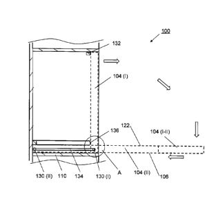
Preferably, when in the vertical position (I) the desk plate 104 is abutted in
proximity to a front
end 104.1 thereof by upper stopping element 132 mounted to the desk enclosure
top wall 108
and in proximity to the rear end 104.2 thereof by front end 136 of left and
right side slide rails
Page 5
CA 3056566 2019-09-24
124, which are mounted to the left and right side cabinet walls 102 a
predetermined distance
above the left and right side guiding grooves 134, respectively.
Alternatively, the upper stopping
element 132 is replaced by stopping elements mounted to the side cabinet walls
102 or by a front
end of the desk enclosure top wall 108 which may be recessed with respect to
the front ends
102.F of the side cabinet walls 102. Further preferably, distance D between
the front ends 136 of
the left and right side slide rails 124 and front end 134.1 of the left and
right side guiding
grooves 134 is determined such that top surface 122 of the desk plate 104 when
in the vertical
position (I) is in close proximity to the front end 134.1 of the left and
right side guiding grooves
134 while the guiding pins 130 are in close proximity to the front end 134.1
of the left and right
side guiding grooves 134, as illustrated in Figures 6 and 7.
Preferably, the left and right side slide rails 134 are placed a predetermined
Distance Ds above a
top surface of the desk enclosure bottom wall 110 and the left and right side
guiding grooves 134
are placed a predetermined Distance DG above the top surface of the desk
enclosure bottom wall
110 such that the desk plate 104 is slidably movable between the top surface
111 of the desk
enclosure bottom wall 110 and a bottom surface 125 of the left and right side
slide rails 124 with
the top surface 122 and a bottom surface 106 of the desk plate 104 being in
close proximity to
the bottom surface 125 of the left and right side slide rails 134 and the top
surface 111 of the
desk enclosure bottom wall 110, respectively. A rear portion of the desk plate
104 is then abutted
in the horizontal position (II) by the guiding pins 130 accommodated in the
respective guiding
grooves 134 and/or by a rear portion of the top surface 122 touching the
bottom surface 125 of
the left and right side slide rails 124, while a mid portion of the bottom
surface 106 touching the
top surface 111 of the desk enclosure bottom wall 110. Furthermore, placement
of the guiding
pins 130 with respect to the rear end 104.2 of the desk plate, the distances
Ds and DG, and bevel
138 of the left and right side slide rails 124 are determined such that the
desk plate 104 is
rotatable when the guiding pins are in position 130 (I), as illustrated in
Figure 7. Optionally, stay
126 is mounted to the rear cabinet wall 112 for abutting a rear portion of the
top surface 122 of
the desk plate 104 when in the horizontal position (II). Further optionally,
edge 104.3 is beveled
to facilitate the rotation of the desk plate 104 about the guiding pin in
position 130 (I). Further
optionally, the slide rails 124 are omitted and the desk plate 104 is abutted
in the vertical
position (I) in proximity to the rear end 104.2 thereof by stopping elements
mounted to the side
cabinet walls 102.
Page 6
CA 3056566 2019-09-24
The desk plate 104 is secured in the vertical position (I) using, for example,
tapered metal pins
116 accommodated in respective bores disposed in the desk enclosure top wall
108 and the front
end 104.1 of the desk plate 104, as illustrated in Figure 1. Alternatively, a
door magnet or a lock
may be employed. Optionally, the metal pins 116 may also be used for securing
the desk plate
104 in the horizontal position (II) by accommodating them in respective bores
disposed in the
stay 126 and a rear portion of the desk plate 104. Handling of the desk plate
104 is facilitated
using, for example, knobs 118 mounted to the bottom surface 106 of the desk
plate 104 in
proximity to the front end 104.1.
Optionally, at least a portion of the bottom surface 106 of the desk plate 104
is adapted to form a
whiteboard.
Optionally, one or more light fixtures 140 are disposed inside the desk
enclosure 128, for
example, mounted to desk enclosure top wall 108, as illustrated in Figure 4.
Further optionally, one or more shelves are disposed inside the desk enclosure
128 and, for
example, height adjustable mounted to the left and right side cabinet walls
102.
Further optionally, electrical outlets are disposed inside the desk enclosure
128, for example,
mounted to the rear cabinet wall 112.
Further optionally, drawer 120 is disposed below the desk enclosure bottom
wall 110 using, for
example, commercially available ball bearing slides.
Further optionally, additional storage space may be provided above the desk
enclosure top wall
108 by extending the left and right side cabinet walls 102 and the rear
cabinet wall 112 upwardly
and by providing top wall 114.
The multi-use desk cabinet 100 may be provided as a unit for being mounted to
a wall or as a
free-standing unit by extending the left and right side cabinet walls 102
downwardly to a floor.
Optionally, a conventional mechanism for adjusting the height of the multi-use
desk cabinet 100
above the floor may be provided.
Page 7
CA 3056566 2019-09-24
In an example implementation of the multi-use desk cabinet 100 the walls,
shelves, and the desk
plate 104 have been made of 3/4" melamine panels and assembled using screw
fasteners and/or
adhesive. The guiding pins 130 are steel pins mounted to the desk plate 104 in
a screw type
fashion. The slide rails 124 and the stay 126 are made of oak and mounted to
the respective walls
using screw fasteners and/or adhesive. The multi-use desk cabinet 100 is
approximately 38"
wide, 48" high (with storage extension above the desk enclosure top wall), and
12" deep. The
desk plate is approximately 36" wide and 25" deep. As is evident to those
skilled in the art, the
multi-use desk cabinet 100 is not limited thereto, but may be adapted for
various uses in different
sizes and made of different materials.
It is noted that while reference has been made to the rear cabinet wall 112
throughout this
disclosure for simplicity, the multi-use desk cabinet 100 is not limited
thereto. Since the rear of
the multi-use desk cabinet 100 is likely placed against a wall, it is
understood that the expression
'rear cabinet wall 112' may refer to any structure for securing the angular
relationship between
the vertically oriented side cabinet walls 102 and the horizontally oriented
desk enclosure top
and bottom walls 108, 110.
The present invention has been described herein with regard to preferred
embodiments.
However, it will be obvious to persons skilled in the art that a number of
variations and
modifications can be made without departing from the scope of the invention as
described
herein.
Page 8
CA 3056566 2019-09-24