Note: Descriptions are shown in the official language in which they were submitted.
CA 03057215 2019-09-18
WO 2018/174806
PCT/SE2018/050308
RLM AND BEAM FAILURE DETECTION BASED ON A MIX OF DIFFERENT
REFERENCE SIGNALS
TECHNICAL BACKGROUND
The present disclosure is generally related to wireless communications systems
and is
more particularly related to radio link monitoring (RLM) and beam-failure
detection by a
wireless device in such systems.
BACKGROUND
Radio Link Monitoring (RLM) in LTE
The Long-Term Evolution (LTE) wireless system developed by the 31d-Generation
Partnership Project (3GPP) is a widely deployed fourth-generation wireless
communications
system. In LTE and its predecessor systems, the purpose of the RLM function in
a wireless
device, referred to in 3GPP documentation as a "user equipment," or "UE," is
to monitor the
downlink radio link quality of the serving cell in RRC_CONNECTED state. This
monitoring
is based on Cell-Specific Reference Signals (CRS), which are always associated
to a given
LTE cell and are derived from the Physical Cell Identifier (PCI). RLM in turn
enables the UE,
when in RRC_CONNECTED state, to determine whether it is in-sync or out-of-sync
with
respect to its serving cell, as described in 3GPP TS 36.213, v14Ø0.
The UE's estimate of the downlink radio link quality, based on its
measurements of the CRS,
is compared with out-of-sync and in-sync thresholds, Qout and Qin
respectively, for the
purposes of RLM. These thresholds are standardized in terms of the Block Error
Rate
(BLER) of a hypothetical Physical Downlink Control Channel (PDCCH)
transmission from
the serving cell. Specifically, Qout corresponds to a 10% BLER, while Qin
corresponds to a
2% BLER. The same threshold levels are applicable whether DRX is in use, or
not.
The mapping between the CRS-based downlink quality and the hypothetical PDCCH
BLER
.. is up to the UE implementation. However, the performance is verified by
conformance tests
defined for various environments, as described in 3GPP TS 36.521-1, v14Ø0.
Also, the
downlink quality is calculated based on the CRS over the whole band, since the
UE does
not necessarily know where PDCCH is going to be scheduled. As illustrated in
Figure 1,
PDCCH transmissions can be scheduled anywhere over the whole downlink
transmission
bandwidth.
When no Discontinuous Reception (DRX) is configured, out-of-sync occurs when
the
downlink radio link quality estimated over a 200-millisecond period becomes
worse than the
threshold Qout. Similarly, without DRX, in-sync occurs when the downlink radio
link quality
estimated over a 100-millisecond period becomes better than the threshold Qin.
Upon
1
CA 03057215 2019-09-18
WO 2018/174806
PCT/SE2018/050308
detection of out-of-sync, the UE initiates the evaluation of in-sync. The
occurrences of out-
of-sync and in-sync are reported internally by the UE's physical layer to its
higher layers,
which in turn may apply layer 3 (i.e., higher layer) filtering for the
evaluation of Radio Link
Failure (RLF). The higher-layer RLM procedure is illustrated in Figure 2.
.. When DRX is in use, the out-of-sync and in-sync evaluation periods are
extended, to enable
sufficient UE power saving, and depend upon the configured DRX cycle length.
The UE
starts in-sync evaluation whenever out-of-sync occurs. Therefore, the same
period
(TEvaluate_Qout_DRX) is used for the evaluation of out-of-sync and in-sync.
However, upon
starting the RLF timer (T310) until its expiry, the in-sync evaluation period
is shortened to
.. 100 milliseconds, which is the same as without DRX. If the timer T310 is
stopped due to
N310 consecutive in-sync indications, the UE performs in-sync evaluation
according to the
DRX based period (TEvaluate_Qout_DRX).
The whole methodology used for RLM in LTE (i.e., measuring the CRS to
"estimate" the
PDCCH quality) relies on the fact that the UE is connected to an LTE cell,
which is the single
.. connectivity entity transmitting both PDCCH and CRSs.
5G Development
A study item for the new 5G radio access technology, entitled New Radio (NR)
has been
started in 3GPP [3GPP RP-1606713]. Companies have agreed on assumptions on the
following design principles: ultra-lean design for the new 5G radio access
technology, which
is referred to as "NR"; and massive usage of beamforming. So far, the details
of RLM have
not been established. However, companies have expressed the view that
beamforming
needs to be taken into account when RLM is designed, which is not the case in
LTE. In
addition to that, concerns have been expressed regarding how the UE should
measure the
quality of a cell.
.. Problems with existing solutions
Following are some of the principles of the 5G NR that may drive the need for
new solutions
for RLM and beam-failure detection, compared to the existing solution in LTE.
Ultra-lean design in the new 5G radio (NR)
NR is expected to be an ultra-lean system, which implies the minimization of
always-on
transmissions, aiming for an energy efficient future-proof system. Early
assumptions in
3GPP show that this principle has been endorsed and there is a common
understanding that
NR should be a lean system. In RAN1#84bis, RAN1 made the following agreements
regarding ultra-lean design:
2
CA 03057215 2019-09-18
WO 2018/174806
PCT/SE2018/050308
The NR design shall strive for maximizing the amount of time and frequency
resources that
can be flexibly utilized or that can be left blanked without causing backward
compatibility
issues in the future. Blank resources can be used for future use. The NR
design shall also
strive for minimizing transmission of always-on signals and confining signals
and channels
for physical layer functionalities (signals, channels, signaling) within a
configurable/allocable
time/frequency resource.
As described above, however, RLM in LTE is based on CRSs, a wide band signal
transmitted
in all subframes. A major consequence of the lean-design principle with
respect to the RLM
design in NR is that there is a wish to avoid the design of a wide band
signals transmitted in
all subframes. Therefore, lean design will prohibit the usage of the LTE
solution for RLM in
NR.
Beam forming in the new 5G radio (NR)
There is a common understanding that NR will consider frequency ranges up to
100 GHz.
In comparison to the frequency bands currently allocated to LTE, some of the
new bands
will have much more challenging propagation properties such as lower
diffraction and higher
outdoor/indoor penetration losses. Consequently, signals will have less
ability to propagate
around corners and penetrate walls. In addition, in high frequency bands,
atmospheric/rain
attenuation and higher body losses render the coverage of NR signals even
spottier.
Fortunately, operation in higher frequencies makes it possible to use smaller
antenna
elements, which enables antenna arrays with many antenna elements. Such
antenna arrays
facilitate beamforming, where multiple antenna elements are used to form
narrow beams
and thereby compensate for the challenging propagation properties. For these
reasons, it is
widely accepted that NR will rely on massive beamforming to provide coverage,
which
means that NR is often referred to as a beam-based system.
It is also known that different antenna architectures should be supported in
NR: analog,
hybrid and digital. This implies some limitations in terms of how many
directions can be
covered simultaneously, especially in the case of analog/hybrid beamforming.
To find a good
beam direction at a given Transmission Reception Point (TRP) / access node /
antenna
array, a beam-sweep procedure is typically employed. A typical example of a
beam-sweep
procedure is that the node points a beam containing a synchronization signal
and/or a beam
identification signal, in each of several possible directions, one or few
directions at a time.
This is illustrated in Figure 3, where each of the illustrated lobes
represents a beam, and
where the beams may be transmitted consecutively, in a sweeping fashion, or at
the same
time, or in some combination. If the same coverage properties apply to both a
3
CA 03057215 2019-09-18
WO 2018/174806
PCT/SE2018/050308
synchronization signal and beam identification signal in each beam, the UE can
not only
synchronize to a TRP but also gain the best beam knowledge at a given
location.
Beam failure detection and recovery
Due to high beamforming gains in NR, the need for some beam failure detection
and
recovery mechanisms emerges as an important issue. Narrow beamforming is
considered
a key component in NR, as it will enable high signal-to-interference-plus-
noise ratio (SINR)
levels at the cell edge, thanks to both higher antenna gains as well as lower
inter-cell
interference, due to pinpointing the signal energy at the desired UE location
via a narrow
beam. However, forming these narrow beams come at the cost of beam pattern
misalignments in high mobility scenarios. If a UE changes its location
suddenly, there will
be sudden alterations in the line-of-sight angle, or, if the beam pattern is
physically
obstructed by a blockage effect in the propagation environment, the quality of
the received
signal may drop sharply. In either case, the network will be required to
monitor and detect
any spontaneous beam failures and perform a beam recovery procedure when
necessary.
The possibility of a UE experiencing sudden decreases in beam quality is a
more significant
issue in NR, compared with legacy systems such as LTE.
Before triggering an RLF procedure or starting to search for a new cell when
the UE assumes
that its serving cell is no longer reachable, it is necessary for a UE to
first detect whether the
link problem can be recovered by switching from one beam to another beam that
is still in
the same serving cell. This is because many beams can share the same baseband
or
antenna board. It is not necessary to reestablish a resource radio control
(RRC) connection
simply because the UE cannot communicate with a single beam, when other beams
in the
same cell are available. A light and fast beam recovery procedure should be
initiated when
there is a beam failure, which can improve UE performance significantly as
compared to
using an RLF procedure.
Mobility reference signal in NR: 3GPP assumptions
In 3GPP discussions so far, there has been some agreement regarding mobility
reference
signals (MRSs) that are used by the UE for measurements related to mobility
(e.g.,
handover, or HO). Agreements for downlink-based mobility in RRC_CONNECTED mode
mobility (optimized for data transmission, at least for network-controlled
mobility) with RRC
involvement, concerning beams and the relation to the NR cell definition, may
include the
following. 1) The UE at least measures one or more individual beams and the
gNB (an NR
base station) should have mechanisms to consider those beams to perform HO.
Note that
this is necessary at least to trigger inter-gNB handovers and to reduce HO
ping-pongs and
HO failures. UEs may report individual and/or combined qualities of multiple
beams. 2) The
4
CA 03057215 2019-09-18
WO 2018/174806
PCT/SE2018/050308
UE should be able to distinguish between the beams from its serving cell and
beams from
non-serving cells for radio resource management (RRM) measurements. The UE
should be
able to determine if a beam is from its serving cell. It is yet to be
determined whether a
serving/non-serving cell may be termed 'serving/non-serving set of beams,'
whether the UE
is informed via dedicated signalling or implicitly detected by the UE based on
some
broadcast signals, and how the cell in connected mode relates to the cell in
idle mode. 3) A
cell quality may be derived based on measurements from individual beams.
Other agreements include that 4) an RRC_CONNECTED UE should be able to perform
RRM
measurements using always-on reference signals (e.g., synchronization signal)
and that 5)
RRC_CONNECTED UEs should be able to perform RRM measurements (measurements
for mobility purposes) on an additional reference signal (e.g., channel state
information
(CSI)-RS, MRS, etc.). 6) The network should be able to configure RRM
measurements via
dedicated signalling to be performed on additional RS and/or IDLE RS.
Agreements also include that there will be 7) support for
variable/configurable demodulation
reference signal (DMRS) patterns for data demodulation, where at least one
configuration
supports a front-loaded DMRS pattern. Agreements also include that 8) at least
an NR
secondary synchronization signal (NR-SSS) is used for a downlink-based RRM
measurement for L3 mobility in IDLE mode. It is yet to be determined whether
there are
potentially additional uses of DM-RS for PBCH (if defined) for measurement in
IDLE mode
and whether the NR-SSS alone will satisfy the requirements for RRM
measurement.
Agreements includes that 9) for CONNECTED mode RRM measurement for layer 3
(L3)
mobility, CSI-RS can be used, in addition to an IDLE mode reference signal.
Detection of
neighbor cells for measurement is based on NR-SS. Agreements also include that
10) beam
failure is defined as PDCCH falling below a certain quality. The network
configures
resources for the UE to transmit a beam link recovery request at least in a
RACH region.
SUMMARY
Described in detail below are techniques by which the wireless device (e.g.,
UE) can
measure its serving cell quality, where a cell is transmitting signals in a
beamforming manner
in a lean design, i.e., without always-on reference signals transmitted in the
whole band and
across all subframes.
Embodiments of the present invention involve a UE and a network radio access
node where
the UE performs RLM based on multiple "sources" that can be used to indicate
to the UE
the quality of a given cell or beam (or the link within a cell). These RLM
measurement
5
CA 03057215 2019-09-18
WO 2018/174806
PCT/SE2018/050308
sources may be two or more different reference signals or a mix of reference
signals and
physical channel quality indicators obtained from non-reference-signal data
(e.g., PDCCH
successful decoding, CSI indications, etc.). For purposes of this description,
beam-failure
detection will be considered a form of RLM. Therefore, while the embodiments
described
herein refer to performing RLM, RLM measurement sources and performing an RLM
action,
these measurement sources and actions are appropriate for and are meant to
include both
beam-failure detection and RLM more generally.
These embodiments may involve RLM that is also based on the estimated quality
of the
main downlink control channel, such as PDCCH, which is monitored by the UE for
scheduling assignments in a connected state. In legacy mobile systems (e.g.,
LTE), the
PDCCH quality is estimated based only on the received signal strength of a
single reference
signal type (e.g., CRS), while these embodiments rely on multiple sources.
Also, in legacy
systems, CRS are always transmitted (so that a single source is always
available), while in
5G, transmissions will be sparse and not always available, so the usage of
multiple sources
becomes an advantageous solution.
One main advantage of the embodiments is that the UE can opportunistically
use, for RLM
and beam failure detection purposes, the PDCCH, DMRSs or PDCCH indications. In
addition, the UE can use additional reference signals (possibly periodic) when
data is not
being scheduled. When a UE is scheduled, RLM based on DMRS is very accurate.
When
UE is not scheduled, no extra overhead is needed for RLM purposes and the UE
can still
estimate a hypothetical PDCCH quality where such hypothetical PDCCH is assumed
to be
configured on similar resources as the additional reference signals.
Benefits of the embodiments include that UEs in a beam-based network can
leverage all
available RS types and monitor the ones that will provide the most accurate
RLM
measurements. So, RLM accuracy is improved. Since UE has the flexibility to
use different
RS types, the network does not need to resort to configuring too many radio
resources to
improve RLM accuracy. If a standalone lean RS is used for RLM, the network may
be
required to configure more frequency resources as proposed in the first and
third solutions
described earlier. Therefore, using different RS types for RLM helps achieve
leaner signaling
in the network.
According to some embodiments, a method in a user equipment (UE) includes
performing
measurements based on a plurality of RLM measurement sources received in beam-
formed
downlink signals, where the measurements indicate a quality of a given cell or
beam. The
plurality of sources includes two or more of: one or more first RSs, one or
more second RSs
6
CA 03057215 2019-09-18
WO 2018/174806
PCT/SE2018/050308
of a different type than the first one or more RSs, and one or more physical
channel quality
indicators obtained from non-reference-signal data in the beam-formed downlink
signals.
For each of the plurality of sources used to perform measurements, the method
includes
determining that a measurement for the respective source indicates an out-of-
sync event in
response to the measurement being below a first threshold. The method further
includes
performing an RLM or beam-failure-detection action based on determined
occurrences of
out-of-sync events.
According to some embodiments, a method in a user equipment (UE) includes
performing,
during a first time interval of an evaluation period, measurements using a RLM
or beam-
failure-detection source received in beam-formed downlink signals, where the
measurements indicate a quality of a given cell or beam. The source includes
one of: one
or more first RSs, one or more second RSs of a different type than the first
one or more RSs,
and one or more physical channel quality indicators obtained from non-
reference-signal data
in the beam-formed downlink signals. The method includes determining a number
of
occurrences of the source during the first time interval from the beginning of
the evaluation
period. The method includes, in response to determining that the number of
occurrences
has met an occurrence threshold, continuing to perform the measurements using
the source
as a primary source for the remainder of the evaluation period. The method
also includes,
in response to determining that the number of occurrences has not met the
occurrence
threshold, selecting, as a secondary source, a different one of the one or
more first RSs,
one or more second RSs and one or more physical channel quality indicators
obtained from
non-reference-signal data in the beam-formed downlink signals, and instead
performing
measurements using the secondary source for the remainder of the evaluation
period. The
method further includes performing an RLM or beam-failure-detection action
based on the
measurements performed using at least one of the primary and secondary
sources.
According to some embodiments, a method in an access node of a wireless
communications
system includes transmitting, in beam-formed downlink signals, a plurality of
RLM or beam-
failure-detection sources, where the plurality of sources comprises one or
more first RSs
and one or more second RSs of a different type than the first one or more RSs.
The method
also includes configuring a UE to perform measurements based on a plurality of
sources
received in the beam-formed downlink signals, wherein the measurements
indicate a quality
of a given cell or beam, where the UE is enabled to perform an RLM or beam-
failure-
detection action based on occurrences of in-sync and out-of-sync events
determined from
the measurements.
7
CA 03057215 2019-09-18
WO 2018/174806
PCT/SE2018/050308
According to some embodiments, a UE includes transceiver circuitry configured
for receiving
beam-formed downlink signals and processing circuitry operatively associated
with the
transceiver circuitry. The processing circuitry is configured to perform
measurements based
on a plurality of RLM measurement sources received in the beam-formed downlink
signals,
where the measurements indicate a quality of a given cell or beam. The
plurality of RLM
measurement sources comprises two or more of: one or more first RSs, one or
more second
RSs of a different type than the first one or more RSs, and one or more
physical channel
quality indicators obtained from non-reference-signal data in the beam-formed
downlink
signals. The processing circuitry is configured to, for each of a plurality of
evaluation periods
and for each of the plurality of RLM measurement sources used to perform
measurements:
determine whether a measurement for the respective RLM measurement source
indicates
an out-of-sync event in response to the measurement being below a first
threshold. The
processing circuitry is also configured to perform one or more RLM actions
based on
determined occurrences of out-of-sync events.
.. According to some embodiments, a UE includes transceiver circuitry
configured for receiving
beam-formed downlink signals and processing circuitry operatively associated
with the
transceiver circuitry. The processing circuitry is configured to perform,
during a first time
interval of an evaluation period, measurements using an RLM source received in
beam-
formed downlink signals, where the measurements indicate a quality of a given
cell or beam.
The RLM measurement source comprises one of: one or more first RSs, one or
more second
RSs of a different type than the first one or more RSs, and one or more
physical channel
quality indicators obtained from non-reference-signal data in the beam-formed
downlink
signals. The processing circuitry is configured to determine a number of
occurrences of the
RLM measurement source during the first time interval from the beginning of
the evaluation
period. The processing circuitry is configured to, in response to determining
that the number
of occurrences has met an occurrence threshold, continue to perform the
measurements
using the RLM measurement source as a primary source for the remainder of the
evaluation
period and, in response to determining that the number of occurrences has not
met the
occurrence threshold, select, as a secondary source, a different one of the
one or more first
RSs, one or more second RSs and one or more physical channel quality
indicators obtained
from non-reference-signal data in the beam-formed downlink signals, and
instead perform
measurements using the secondary source for the remainder of the evaluation
period. The
processing circuitry is also configured to perform one or more RLM actions
based on the
measurements performed using at least one of the primary and secondary
sources.
8
CA 03057215 2019-09-18
WO 2018/174806
PCT/SE2018/050308
According to some embodiments, an access node of a wireless communications
system
includes transceiver circuitry configured for transmitting beam-formed
downlink signals and
communicating with a UE and processing circuitry operatively associated with
the
transceiver circuitry. The processing circuitry is configured to transmit, in
beam-formed
downlink signals via the transceiver circuitry, a plurality of RLM measurement
sources,
where the plurality of RLM measurement sources comprises one or more first RSs
and one
or more second RSs of a different type than the first one or more RSs. The
processing
circuitry is also configured to configure the UE to perform measurements based
on a plurality
of RLM measurement sources received in the beam-formed downlink signals, where
the
measurements indicate a quality of a given cell or beam, thereby enabling the
UE to perform
one or more RLM actions based on occurrences of in-sync and out-of-sync events
determined from the measurements.
Further aspects of the present invention are directed to an apparatus,
computer program
products or computer readable storage medium corresponding to the methods
summarized
above and functional implementations of the above-summarized apparatus and UE.
Of course, the present invention is not limited to the above features and
advantages. Those
of ordinary skill in the art will recognize additional features and advantages
upon reading the
following detailed description, and upon viewing the accompanying drawings.
BRIEF DESCRIPTION OF THE FIGURES
Figure 1 illustrates how PDCCH can be scheduled anywhere over the whole
downlink
transmission bandwidth.
Figure 2 illustrates higher layer RLM procedures in LTE.
Figure 3 illustrates a beam sweeping procedure.
Figure 4 illustrates the principles of a reference signal transmission that
facilitates RLM
procedures described herein, according to some embodiments.
Figure 5 is a block diagram of a wireless device, according to some
embodiments.
Figure 6 illustrates a method in the wireless device, according to some
embodiments.
Figure 7 is a diagram illustrating one SINR per source that is generated per
evaluation
period, according to some embodiments.
Figure 8 is a diagram illustrating one SINR that is generated per evaluation
period, although
a different source could be used per evaluation period, according to some
embodiments.
9
CA 03057215 2019-09-18
WO 2018/174806
PCT/SE2018/050308
Figure 9 illustrates another method in the wireless device, according to some
embodiments.
Figure 10 is a flowchart illustrating the use of single set of parameters
during an RLM/RLF
procedure, according to some embodiments.
Figure 11 is a flowchart illustrating the use of multiple sets of parameters
during an
RLM/RLF procedure, according to some embodiments.
Figure 12 is a flowchart illustrating the use of multiple sets of parameters
during an
RLM/RLF procedure, where some parameters are shared by a different source,
according to
some embodiments.
Figure 13 is a block diagram of a network node, according to some embodiments.
.. Figure 14 illustrates a method in the network node, according to some
embodiments.
Figure 15 is a diagram illustrating PDCCH and DMRS on a similar beam pattern,
according
to some embodiments.
Figure 16 is a diagram illustrating PDCCH and DMRS on similar frequency
resources,
according to some embodiments.
Figure 17 is a diagram illustrating a mobility RS and PDCCH resource
configuration,
according to some embodiments.
Figure 18 is a diagram illustrating mobility RS and PDCCH on different beams,
according to
some embodiments.
Figure 19 is a diagram illustrating a mobility RS configuration with PDCCH
occasions,
according to some embodiments.
Figure 20 is a diagram illustrating a mobility RS configuration outside all
PDCCH occasions,
according to some embodiments.
Figure 21 is a diagram illustrating a mobility RS configuration outside PDCCH
occasions with
RLM periodicity, according to some embodiments.
Figure 22 is a block diagram illustrating a functional implementation of a
wireless device,
according to some embodiments.
Figure 23 is a block diagram illustrating another functional implementation of
the wireless
device, according to some embodiments.
Figure 24 is a block diagram illustrating a functional implementation of a
network node,
according to some embodiments.
CA 03057215 2019-09-18
WO 2018/174806
PCT/SE2018/050308
DETAILED DESCRIPTION
As described above, common signals and channels in LTE are transmitted in an
omnidirectional manner, i.e., without beamforming. That is the not the case in
NR, with the
availability of many antennas at the base station and the different ways they
can be
combined to beamform signals and channels. The major consequence of the
massive usage
of beamforming in NR is that while in LTE it was quite clear that the CRSs
quality could be
used to estimate the quality of PDCCH, in NR this becomes unclear, due to the
different
ways channels and reference signals can be beamformed. In other words, it
cannot be
assumed as a general matter that any particular reference signal will be
transmitted in the
.. same way as the PDCCH is transmitted. This ambiguity from the UE's point of
view is due
to that reference signals and channels can be transmitted by the network via
different kinds
of beamforming schemes, which are typically determined based on real-time
network
requirements. These requirements may include, for example, different tolerance
levels to
radio overhead due to reference signals versus control channels, or different
coverage
.. requirements for reference signals versus control channels.
Despite these two challenges from NR design principles, an NR UE in connected
mode still
needs to perform RLM, to verify whether its cell quality is still good enough
so that the UE
can be reached by the network. Otherwise higher layers should be notified, and
UE
autonomous actions should be triggered.
.. A first proposed solution for RLM in networks where beamforming is used
includes a UE
performing RLM by performing Radio Resource Management (RRM) measurements
based
on the same periodic RSs configured to support connected mode mobility. At the
network
side, the radio access node transmits downlink control channel information in
the same way
it transmits these reference signals to be reused for RLM purposes. In this
context,
"performing RLM" means performing RRM measurements and comparing the value of
a
given metric, e.g., a radio signal Received Power (RSRP), with a threshold
that represents
the downlink control channel quality, e.g., in terms of Block Error Rate
(BLER), under the
assumption that the control channel would have been transmitted in the same
manner, i.e.,
with similar beamforming properties and/or similar or representative frequency
resources.
.. One aspect of this approach is that the network guarantees the correlation
of the quality of
the serving cell's beamformed RSs used for mobility measurements and the
quality of the
downlink control channel(s) obtained from non-reference-signal data.
"Correlated with" here
indicates that the frequency resources for the beamformed RSs are overlapping
with or very
close to those used for the downlink channel, within the overall possible
bandwidth. This
correlation is done at the network side by beamforming the downlink control
channel
11
CA 03057215 2019-09-18
WO 2018/174806
PCT/SE2018/050308
information in the same beamforming configuration (e.g., direction, beam
width, power
distribution, same antenna panel, etc.) in the same manner it is transmitting
the mobility RSs
configured for that UE.
Figure 4 illustrates principles of a reference signal transmission that
facilitate the RLM
performed by this example system. As seen on the left-hand side of Figure 4,
each beam
carries RSs that are configured to the UE primarily for mobility purposes.
What is meant by
"configured to the UE" is that a connected-mode UE is provided with
information regarding
measurements and reporting conditions, with respect to serving cell/beam
signals and/or
non-serving cell/beam signals. These RSs may carry a beam identifier (ID), a
beam ID plus
a group ID (which may be understood as a cell ID, for example), or simply a
group ID, in
various embodiments. As seen on the right-hand side of Figure 4, a downlink
control
channel, such as a PDCCH, is transmitted using the same beamforming properties
as the
RSs that are used for mobility purposes. This may be understood as
transmitting the
downlink control channel in the "same beam" as the RSs, even if transmitted at
different
times.
However, in order to fulfill requirements for RRM measurements, these
beamformed RSs
used for mobility measurements have been envisioned to be narrow band signals
(e.g., six
central physical resource blocks (PRBs)). On the other hand, the downlink
control channel
can either be transmitted in the whole band (as LTE PDCCH) or
localized/distributed (as
LTE ePDCCH and possibly the downlink control channel design in NR).
In a second proposed solution, the access node may perform RLM measurements
based on
a new signal that is a version of the beamformed RSs used for mobility
measurements , but
repeated in the frequency domain in the same frequency resources of the search
space of
the DL control channel of a given UE. These multiple versions of the
beamformed RSs used
for mobility may also be transmitted in different subframes in order to
provide some
additional time-domain diversity and/or to enable the beamforming transmission
to be
equivalent.
However, as the demodulation of PDCCH is still based on DM RS, there could
possibly be a
mismatch between the beamforming applied to the RSs used for mobility and the
beamforming applied on PDCCH. Such a mismatch may be present even if the
transmissions of both the RSs and PDCCH are configured on the same frequency
resources.
In a third proposed solution, RLM can be based on a UE-specific RS, such as
DMRS, since
DM RS already needs to be configured on the same resources as PDCCH and
transmitted
with the same beamforming pattern so that PDCCH can be decoded reliably based
on
12
CA 03057215 2019-09-18
WO 2018/174806
PCT/SE2018/050308
DMRS. In this configuration, such DMRS can accurately reflect the PDCCH
quality and is
therefore suitable for RLM.
However, DMRS is configured by the network only when UE is scheduled with
PDCCH. The
UE cannot monitor its radio link quality if no PDCCH is scheduled for that UE.
To solve this
issue, the third proposed solution may also include an instance where the UE
is enabled to
perform RLM in an opportunistic manner in a beam-based system, where the
network may
configure UE with a UE-specific RS transmission, even when the UE is not
scheduled with
any PDCCH. This UE-specific RS can be configured as a DMRS or as a dummy PDCCH
transmission, which is transmitted on a UE-specific beamforming pattern. This
solution
provides high measurement accuracy for the RLM function; however, such gain in
RLM
performance comes at the cost of extra radio signaling overhead. This overhead
can be
detrimental to the network performance, especially if non-scheduled PDCCH
durations are
long and if there is a large number of RRC_CONNECTED UEs performing RLM
measurements.
There are limitations when using a single RS configuration for RLM. The first
and second
proposed solutions rely solely on a single configuration of beamformed signals
used for
mobility and reused for RLM. When PDCCH and RSs used for mobility are both
transmitted
on similar resources through the same beamforming pattern, the RLM
measurements can
be performed accurately at UE. However, one of the essential benefits in a
beam-based
system is the dynamic and opportunistic UE-specific configuration of data and
control
channels. For example, a UE-specific narrow beam-width pattern can be formed
by the
network to reach a distant connected-mode UE with high antenna directivity so
that spectral
efficiency can be maximized on data channels by fully taking advantage of the
UE-specific
propagation conditions. The control channel also needs to be coupled on the
same beam
pattern as the data channel to ensure that the data channel can be decoded at
all times.
Hence, RSs used for mobility as a single source cannot render accurate RLM
performance
in such beam-based networks where UE-specific beam patterns are configured
opportunistically. In summary, the solutions based on beamformed RSs used for
mobility
require low signaling overhead; however, the accuracy of RLM measurements
cannot be
high in opportunistic beam-based networks with dynamic UE-specific beam
configurations.
The third proposed solution relies solely on UE-specific RS (e.g., DMRS) for
RLM. When UE
is scheduled with PDCCH, there is no overhead, since the DMRS is transmitted
anyway.
However, when no PDCCH is scheduled by the network due to packet data
inactivity, the
opportunistic RLM solution may result in significant overhead. The amount of
overhead can
be especially high when a large number of RRC_CONNECTED UEs are required to
perform
13
CA 03057215 2019-09-18
WO 2018/174806
PCT/SE2018/050308
RLM measurements. This issue cannot be avoided, since each active UE relies on
a UE-
specific RS to perform RLM according to the third proposed solution. In
summary, the UE-
specific RS based solution can ensure high RLM accuracy in a beam-based
network;
however, the signaling overhead may be too high in crowded beam-based networks
especially when the traffic patterns of user data packets are intermittent and
fragmented.
Therefore, it is recognized herein that the inherent limitations of using a
single beamformed
RS configuration during RLM measurements provides performance drawbacks in a
beam-
based system where lean signaling is an essential performance indicator. Each
RS type has
a clear superiority for RLM depending on different link and network conditions
in a beam-
based lean system.
Figure 5 illustrates a diagram of the corresponding wireless device, shown as
wireless
device 50, according to some embodiments. The wireless device 50 may be
considered to
represent any wireless terminals that may operate in a network, such as a UE
in a cellular
network. Other examples may include a communication device, target device,
device to
.. device (D2D) UE, machine type UE or UE capable of machine to machine
communication
(M2M), a sensor equipped with UE, PDA (personal digital assistant), Tablet,
mobile terminal,
smart phone, laptop embedded equipped (LEE), laptop mounted equipment (LME),
USB
dongles, Customer Premises Equipment (CPE), etc.
The wireless device 50 is configured to communicate with a radio network node
or base
station in a wide-area cellular network via antennas 54 and a transceiver
circuit 56. The
transceiver circuit 56 may include transmitter circuits, receiver circuits,
and associated
control circuits that are collectively configured to transmit and receive
signals according to
a radio access technology, for the purposes of using cellular communication
services. This
radio access technology is NR for the purposes of this discussion.
The wireless device 50 also includes one or more processing circuits 52 that
are operatively
associated with the radio transceiver circuit 56. The processing circuit 52
comprises one or
more digital processing circuits 62, e.g., one or more microprocessors,
microcontrollers,
Digital Signal Processors (DSPs), Field Programmable Gate Arrays (FPGAs),
Complex
Programmable Logic Devices (CPLDs), Application Specific Integrated Circuits
(ASICs), or
any mix thereof. More generally, the processing circuit 52 may comprise fixed
circuitry, or
programmable circuitry that is specially adapted via the execution of program
instructions
implementing the functionality taught herein, or may comprise some mix of
fixed and
programmed circuitry. The processing circuit 52 may be multi-core.
14
CA 03057215 2019-09-18
WO 2018/174806
PCT/SE2018/050308
The processing circuit 52 also includes a memory 64. The memory 64, in some
embodiments, stores one or more computer programs 66 and, optionally,
configuration data
68. The memory 64 provides non-transitory storage for the computer program 66
and it may
comprise one or more types of computer-readable media, such as disk storage,
solid-state
memory storage, or any mix thereof. Here, "non-transitory" means permanent,
semi-
permanent, or at least temporarily persistent storage and encompasses both
long-term
storage in non-volatile memory and storage in working memory, e.g., for
program execution.
By way of non-limiting example, the memory 64 comprises any one or more of
SRAM,
DRAM, EEPROM, and FLASH memory, which may be in the processing circuit 52
and/or
separate from processing circuit 52. In general, the memory 64 comprises one
or more types
of computer-readable storage media providing non-transitory storage of the
computer
program 66 and any configuration data 68 used by the user equipment 50. The
processing
circuit 52 may be configured, e.g., through the use of appropriate program
code stored in
memory 64, to carry out one or more of the methods and/or signaling processes
detailed
hereinafter.
The processing circuit 52 of the wireless device 50 is configured, according
to some
embodiments, to perform measurements based on a plurality of RLM sources
(inclusive of
any beam-failure detection sources) received in beam-formed downlink signals,
where the
measurements indicate a quality of a given cell or beam. The plurality of RLM
measurement
sources comprises two or more of: one or more first RSs, one or more second
RSs different
than the first one or more RSs, e.g., of a different type than the one or more
first RSs, and
one or more physical channel quality indicators obtained from non-reference-
signal data in
the beam-formed downlink signals. The processing circuit 52 is also configured
to, for each
of a plurality of evaluation periods and for each of the plurality of RLM
measurement sources
used to perform measurements, determine whether a measurement for the
respective RLM
measurement source indicates an out-of-sync event in response to the
measurement being
below a first threshold or determine whether the measurement for the
respective RLM
measurement source indicates an in-sync event in response to the measurement
being
above a second threshold. The processing circuit 52 is further configured to
perform one or
more RLM actions (inclusive of any beam-failure detection actions) based on
determined
occurrences of in-sync and/or out-of-sync events.
According to some embodiments, the processing circuit 52 is configured to
perform a method
600, as shown in Figure 6. The method 600 includes performing measurements
based on a
plurality of RLM measurement sources received in beam-formed downlink signals,
where
the measurements indicate a quality of a given cell or beam (block 602). The
plurality of
CA 03057215 2019-09-18
WO 2018/174806
PCT/SE2018/050308
RLM measurement sources comprises two or more of: one or more first RSs, one
or more
second RSs different than the first one or more RSs, and one or more physical
channel
quality indicators obtained from non-reference-signal data in the beam-formed
downlink
signals. The method 600 also includes, for each of a plurality of evaluation
periods and for
each of the plurality of RLM measurement sources used to perform measurements,
determining that a measurement for the respective RLM measurement source
indicates an
out-of-sync event in response to the measurement being below a first threshold
(block 604).
Likewise, the method may also include, for each of a plurality of evaluation
periods and for
each of the plurality of RLM measurement sources used to perform measurements,
determining that the measurement for the respective RLM measurement source
indicates
an in-sync event in response to the measurement being above a second threshold
(block
606). In some cases, blocks 604 and 606 may be considered part of a broader
step of
determining whether to declare RLF or beam detection failure. A broader step
may also
include determining whether each measurement indicates an in-sync event or an
out-of-sync
event. The method 600 further includes performing one or more RLM actions
based on the
measurements. This may include performing an RLM action based on determined
occurrences of in-sync and out-of-sync events (block 608).
In various cases, the plurality of RLM measurement sources may comprise any DM
RSs or
physical channel quality indicators. For example, RLM measurement sources may
include
DMRSs used for a physical control channel region of the beam-formed downlink
signals in
combination with one or more of primary synchronization signals (PSSs),
secondary
synchronization signals (SSSs), tertiary synchronization signals (TSSs), and
DMRSs used
for a physical broadcast channel (PBCH). The DM RSs may be used for the
physical control
channel region in combination with one or more of CSI-RSs, beamformed RSs used
for
mobility, and beam measurement reference signals (BRSs). RLM measurement
sources
may also include a physical channel quality indicator obtained from non-
reference-signal
data in the beam-formed downlink signals in combination with the one or more
of PSSs,
SSSs, TSSs and DMRSs used for the PBCH. The physical channel quality indicator
may be
used in combination with the one or more of CSI-RSs, beamformed RSs used for
mobility,
and BRSs.
Performing the RLM action based on the determined occurrences of in-sync
and/or out-of-
sync events may comprise performing a first RLM action in response to
determining that a
threshold number of consecutive out-of-sync events has occurred and performing
a second
RLM action in response to determining that a threshold number of consecutive
in-sync
events has occurred. In one example, the first RLM action comprises starting a
timer and
16
CA 03057215 2019-09-18
WO 2018/174806
PCT/SE2018/050308
the second RLM action comprises stopping the timer. In another example, one of
the first
and second RLM actions comprises providing higher layer notifications or
declaring RLF
and/or declaring beam failure.
In some embodiments, the threshold number of consecutive out-of-sync events
and the
threshold number of consecutive in-sync events are established separately for
each RLM
measurement source of the plurality of RLM measurement sources. In other
embodiments,
the threshold number of consecutive out-of-sync events and/or the threshold
number of
consecutive in-sync events for one or more of the plurality of RLM measurement
sources is
shared by a different RLM measurement source.
As can be seen, there may be several parameters involved in these embodiments:
an out-
of-sync measurement threshold (Qout); an in-sync measurement threshold (Qin);
an out-of-
sync occurrence number threshold (Ni); an in-sync occurrence number threshold
(n2); and
a timer value (Ti). Different sources can use either of the parameters, or
different
parameters. And each different source can have its own procedure during RLM or
alternatively different RLM measurement sources can be used in one procedure
during RLM.
In the embodiments described herein, only RLM is mentioned for simplicity, but
RLM is
meant to include beam failure detection as a form of RLM, as mentioned above.
The method 600 may include receiving configuration information for one or more
of the
plurality of RLM measurement sources and performing the measurements based on
the
configuration information.
There may be different methods for performing the measurements for RLM (and
beam failure
detection). In a first alternative method, the wireless device (e.g., UE)
monitors its configured
PDCCH and, if data is scheduled in a given subframe, the UE should
opportunistically use
PDCCH DMRSs to compute a quality estimate. This may be an SINR value that is
further
averaged over multiple PDCCH occasions in a pre-defined interval called an
evaluation
period, which may be, for example, X radio frames (e.g., 20 radio frames = 200
ms). At the
same time, within the same evaluation period, the UE may measure an additional
source,
which in the case of measuring a first source, could mean measuring an SS
Block RS (e.g.
PSS/SSS/TSS or DM RS for PBCH). In the case of measuring the second source,
this could
be CSI-RSs so the UE also generates an averaged quality estimate (e.g., SINR
associated
to the additional sources over the same period). Hence, in this first
alternative, for each RLM
evaluation period, there will be one average quality estimate, such as one
SINR estimate
per source.
17
CA 03057215 2019-09-18
WO 2018/174806
PCT/SE2018/050308
In an embodiment of this first alternative, the method 600 may include
performing the
measurements based on the plurality of RLM measurement sources, where this
includes
monitoring a control channel region of one or more of the beam-formed downlink
signals
and associated with a control channel message for the wireless device. In
response to
determining that data is scheduled in a given subframe of the control channel
region, the
method may include determining, during an evaluation period, a first
measurement by
computing a first quality estimate using one or more first RSs, wherein the
first RSs are
DMRSs in the control channel region. The method may further include
determining, during
the evaluation period, a second measurement by computing a second quality
estimate using
the one or more second RSs, wherein the one or more second RSs are one of: one
or more
PSSs; one or more SSSs, one or more TSSs, one or more DMRSs used for a PBCH,
one
or more of CSI-RSs, one or more beamformed RSs used for mobility, and one or
more BRSs.
The first quality estimate may be computed as an average of first radio signal
metrics
measured from the one or more first RSs over the evaluation period, and the
second quality
.. estimate may be computed as an average of second radio signal metrics
measured from the
one or more second RSs over the evaluation period.
This quality estimate, or average quality estimate, may be an SINR. Figure 7
shows the
generation of one SINR per source per evaluation period. For example, Figure 7
shows
evaluation periods 702, 704 and 706. In other words, if K sources are defined
there will be
K SINR values per period. One aspect of this embodiment is that K quality
estimates (e.g.,
SINR values) are generated for K RLM sources per measurement evaluation
period. In
current systems, only a single quality estimate based on a single source is
generated (the
CRS in the case of LTE). Figure 8 shows an embodiment where one SINR is
generated per
evaluation period, although a different source could be used per evaluation
period. For
example, in a first evaluation period 702 PDCCH DMRS is used to calculate a
SINR average.
In the next evaluation period 704, SS Block RS or CSI-RS is used.
In a second alternative for performing the measurements for RLM, the notion of
primary RLM
source and secondary RLM sources is introduced. In this embodiment, the UE
will always
start performing RLM associated to the primary RLM source to perform RLM
measurements
and, if that is not present or does not provide sufficient samples, the UE
should use
secondary sources. For example, PDCCH DMRS could be the primary source,
possibly
available only when data is being scheduled to the UE. Then, when monitoring
PDCCH, the
UE should detect whether the number of PDCCH occurrences are likely sufficient
(i.e., above
a configurable threshold) within a given time interval from the beginning of
the evaluation
period (e.g., first X radio frames). This is shown by interval 802 in
evaluation period 704 of
Figure 8. If they are sufficient (e.g., PDCCH occasions within the first X
radio frames meet
18
CA 03057215 2019-09-18
WO 2018/174806
PCT/SE2018/050308
the threshold), the UE should keep using it as the RLM source for that
measurement
evaluation period 704, or at least the remainder 804 of the evaluation period
704. If the
number of occurrences during the interval 802 is not sufficient (e.g., PDCCH
occasions
within the first X radio frames lower than threshold), the UE should start
searching for
.. additional expected source(s). The UE will then perform quality estimation,
such as SINR
estimation, for that same measurement evaluation period 704, now based on the
secondary
source(s), which may have been selected based on a number of factors, such as
current
measurements, past measurements, historic reliability, what other sources may
be available
or detected, etc. Hence, in this second alternative, for each measurement
evaluation period,
there will be a single quality estimation, such as an SINR estimation, which
can be either
associated to the primary or secondary source(s).
Note that in current systems, a single source is always used (CRS in LTE). One
aspect of
the embodiment is that quality estimates, such as SINR estimates, for each
measurement
evaluation period may have been generated based on different RLM sources. For
example,
while in the first period 702, the DMRS for PDDCH is used (since there was
scheduled data),
in the second evaluation period 704 NR-SS or CSI-RS are used as there are not
enough
samples from DMRS of PDCCH.
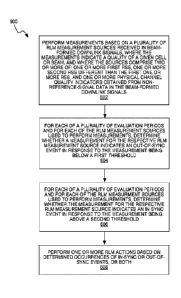
Accordingly, in some embodiments, the processing circuit 52 of the wireless
device 50 is
configured to perform method 900. The method 900 includes performing, during a
first time
interval of an evaluation period, measurements using a RLM measurement source
received
in beam-formed downlink signals, where the measurements indicate a quality of
a given cell
or beam (block 902). The RLM measurement source comprises one of: one or more
first
RSs, one or more second RSs different (e.g., of a different type) than the
first one or more
RSs, and one or more physical channel quality indicators obtained from non-
reference-
signal data in the beam-formed downlink signals. The method 900 also includes
determining
a number of occurrences of the source during the first time interval from the
beginning of the
evaluation period (block 904). The method 900 includes, in response to
determining that the
number of occurrences has met an occurrence threshold, continuing to perform
the
measurements using the source as a primary source for the remainder of the
evaluation
period (block 906) and, in response to determining that the number of
occurrences has not
met the occurrence threshold, selecting, as a secondary source, a different
one of the one
or more first RSs, one or more second RSs and one or more physical channel
quality
indicators obtained from non-reference-signal data in the beam-formed downlink
signals,
and instead performing measurements using the secondary source for the
remainder of the
evaluation period (block 908). The method 900 further includes performing one
or more RLM
19
CA 03057215 2019-09-18
WO 2018/174806
PCT/SE2018/050308
actions based on the measurements performed using at least one of the primary
and
secondary sources (block 910).
Performing the measurements using the primary source may include computing a
first
quality estimate for the evaluation period from one or more first radio signal
metrics obtained
from the primary source, and performing the measurements using the secondary
source
may include computing a second quality estimate for the evaluation period from
one or more
second radio signal metrics obtained from the secondary source. The method 900
may then
further include performing the one or more RLM actions based on the first
quality estimate
in response to determining that the number of occurrences has met the
occurrence threshold
and performing the RLM actions based on the second quality estimate in
response to
determining that the number of occurrences has not met the occurrence
threshold.
In various cases, the primary source is one or more DMRS in a control channel
region of the
beam-formed downlink signals, and the secondary source is one of: one or more
PSSs; one
or more SSSs, one or more TSSs, one or more DMRSs used for a PBCH, one or more
of
CSI-RSs, one or more MRSs, and one or more BRSs. In some cases, the sources
used for
the primary and secondary sources may be switched.
In a third alternative for performing measurements for RLM, after detecting
that the primary
source may not provide enough occasions and starting to use the secondary
source, the UE
does not discard the samples but rather waits for further or new occurrences
of the primary
source. If there are a sufficient number of new occurrences, at the end of the
period, the UE
will generate two SINRs, one associated with the primary source and another
associated
with the secondary source(s). Here, there can either be a single SINR value
that is generated
per period or multiple SINR values per period. In the case of a single source,
that source
may change per period.
Accordingly, in some embodiments, the method 900 includes, in response to
determining a
threshold number of new occurrences of the primary source have occurred during
the
evaluation period after beginning to perform the measurements using the
secondary source,
continuing with performing the measurements using the primary source for the
evaluation
period. Performing the RLM actions based on the measurements may include
selecting
whether to use the measurements performed using the primary source. The
measurements
may be performed using the secondary source, or both, based on the respective
measurements, and performing the RLM actions based on the selection.
CA 03057215 2019-09-18
WO 2018/174806
PCT/SE2018/050308
For any of these alternatives, in the case that the secondary source is a
signal transmitted
in the synchronization signal (SS) Block Set, the UE can expect that signal
once it has
detected the absence of DMRS for PDCCH. In the case of CSI-RS, the UE may need
to wait
for its occurrence within that radio frame, depending on the CSI-RS
configuration for its
.. serving cell. In some cases, the UE does not really perform SINR averages
for PDCCH but
uses other quality indications, such as the CQI reports associated to that
specific scheduled
subframe (possibly over multiple resource elements in the frequency domain
within the
PDCCH search space). However, if PDCCH is equally not present, the triggering
to search
additional sources in the serving cell can be similar.
Note that although the first step described above is one in which the UE
performs
measurements, prior to performing measurements, the UE may have been provided
with a
measurement configuration associated to RLM by the network, for example, at
the moment
it connects to the cell (upon transition to RRC_CONNECTED or via a handover).
In the case
of PDCCH DMRS, the UE could be provided with a subset of the time intervals of
its PDCCH
search space. In the case of the additional sources being the NR-SS, the UE
can be
configured with time-domain filtering parameters which may be different from
the ones used
for mobility measurements events (e.g., A1-A6 or equivalent). In the case that
the CSI-RS
is used as an additional RLM source, the UE may receive an additional
configuration only
for RLM purposes, which gives the flexibly to the network to match the PDCCH
search space
in the frequency domain with the CSI-RS occurrence for RLM (also beamformed in
the same
way the network would beamform PDCCH). For example, the CSI-RS used for beam
management may be transmitted quite often and with a certain bandwidth BW_CSI-
RS,
while the UE may be configured for RLM to measure on specific part of the CSI-
RS
bandwidth that matches that of the PDCCH.
Therefore, in some embodiments, the method 900 includes the wireless device
receiving
configuration information from the network for one or more of the plurality of
RLM
measurement sources and performing the measurements based on the configuration
information. In other embodiments, the method 900 includes receiving
configuration
information for at least one of the primary and secondary sources and
performing the
measurements based on the configuration information.
There may be various methods for mapping RLM measurements to either in-sync or
out-of-
sync events. Once averaged SINR (or other quality metric) measurements are
available per
RLM source within a given RLM measurement evaluation period, the UE maps the
SINR (or
other quality estimates) value or values per source into in-sync and out-of-
sync events per
.. evaluation period. This step may involve at least two different
alternatives. In one alternative,
21
CA 03057215 2019-09-18
WO 2018/174806
PCT/SE2018/050308
the UE has a single quality estimate, such as an SI N R estimate, per
evaluation interval (or
any other pre-defined RLM time interval). The single quality estimate will
have been
generated from or will be associated with one of the multiple sources. In
another alternative,
the UE has one quality estimate per RLM source per evaluation interval (or any
other pre-
.. defined RLM time interval), one per source that was used to generate it.
In the case of a single quality estimate per evaluation period, when no
discontinuous
reception (DRX) is configured, the UE triggers one out-of-sync event for each
evaluation
period when the single quality estimate becomes worse than a configured
threshold (Qout).
Similarly, without DRX, the in-sync is triggered when the quality estimate
becomes better
.. than a configured threshold (Qin). Upon detection of an out-of-sync event
in a measurement
evaluation period, the UE initiates the evaluation of in-sync (within another
in-sync
evaluation period which can be shorter). The occurrences of out-of-sync and in-
sync are
reported internally by the UE's physical layer to its higher layers, which in
turn may apply
layer 3 (i.e., higher layer) filtering for the evaluation of RLF.
.. In a first approach, the thresholds Qin and Qout are configured per
evaluation period,
regardless of which source is being used. Hence, RLM recovery actions may be
triggered
based on mixed occurrences of out-of-sync events, possibly from multiple
sources. The
occurrences of out-of-sync and in-sync are reported internally by the UE's
physical layer to
its higher layers regardless which RLM source was responsible to increment the
out-sync
and in-sync events.
According to this first approach, an embodiment of a method for performing the
RLM actions
based on the measurements may include determining that a measurement obtained
for
whichever one of the primary or secondary sources was used for the remainder
of the
evaluation period indicates an out-of-sync event in response to the
measurement being
below a first threshold or determining that the measurement indicates an in-
sync event in
response to the measurement being above a second threshold. The method may
then
include performing an RLM action based on determined occurrences of in-sync
and out-of-
sync events.
In a second approach, the thresholds Qin and Qout are configured per
evaluation period,
regardless of which source is being used. However, the increments are done per
RLM
source. Hence, RLM recovery actions may be triggered based on occurrences of
out-of-sync
events per source although threshold values are the same. The occurrences of
out-of-sync
and in-sync are reported internally by the UE's physical layer per source to
its higher layers.
22
CA 03057215 2019-09-18
WO 2018/174806
PCT/SE2018/050308
According to this second approach, an embodiment of performing the RLM
measurement
actions based on the measurements includes, for each RLM measurement source
used to
perform measurements, determining that a measurement for the respective RLM
measurement source during the evaluation period indicates an out-of-sync event
in
.. response to the measurement being below a first threshold and determining
that the
measurement for the respective RLM measurement source during the evaluation
period
indicates an in-sync event in response to the measurement being above a second
threshold.
The method then includes performing one or more RLM actions based on
determined
occurrences of in-sync and out-of-sync events.
.. In some embodiments, performing the RLM actions based on the determined
occurrences
of in-sync and out-of-sync events includes performing a first RLM action in
response to
determining that a threshold number of consecutive out-of-sync events has
occurred and
performing a second RLM action in response to determining that a threshold
number of
consecutive in-sync events has occurred. The first RLM action may include
triggering a timer
and the second RLM action may include stopping the timer. In other
embodiments, one of
the first and second RLM actions comprises providing higher layer
notifications, declaring
RLF or declaring beam failure.
In some cases, the threshold number of consecutive out-of-sync events and the
threshold
number of consecutive in-sync events are established separately for each of
the primary
and secondary sources.
In a third approach for this step of performing the RLM actions, the
thresholds Qin and Qout
are configured per evaluation period and per RLM measurement source. That is,
there can
be different values per RLM measurement source so that for a given quality
estimate, such
as a given SINR estimate, an out-of-sync event for one RLM measurement source
may
increment but not for the other. As in the second approach, the increments are
done per
RLM measurement source. Hence, RLM recovery actions may be triggered based on
occurrences of out-of-sync events per source and different threshold can apply
since actions
can also be different, depending on the higher layers. The occurrences of out-
of-sync and
in-sync are reported internally by the UE's physical layer per source to its
higher layers,
.. which in turn may apply higher layer filtering for the evaluation of RLF.
In some cases, at least one of the threshold number of consecutive out-of-sync
events and
the threshold number of consecutive in-sync events for one of the primary and
secondary
sources is shared by a different RLM measurement source than the primary and
secondary
sources.
23
CA 03057215 2019-09-18
WO 2018/174806
PCT/SE2018/050308
Multiple (per source) quality estimates may be made per evaluation period
(i.e., multiple
SINR values). In a first example of multiple quality estimates, such as
multiple SINR
estimates per evaluation period, the UE selects a single quality estimate
(SINR estimate)
per evaluation period. To detect an out-of-sync or an in-sync event, the UE
may combine
the quality estimates from the sources. The previous description based on the
usage of a
single quality estimate (SINR estimate) per period described above may also
apply to this
approach.
In a second example, the UE can use the multiple quality estimates to
increment out-of-sync
and in-sync events per source, independently. Herein, the second and third
approaches of
the single quality estimate per evaluation period case also apply except that
instead of one
increment per period there can be multiple, one per source depending on each
quality
estimate.
Performing an action may include the UE generating or monitoring RLM-related
events (e.g.,
starting a timer, notification to higher layers, RLF declaration, etc.)
depending on the
occurrences of in-sync and out-sync events. The determined increments of out-
of-sync
events and in-sync events may be reported to higher layers, where thresholds
for the
maximum number of events are configured. The UE may be able to verify, for
each period,
whether the number of out-of-sync events are higher than pre-defined
threshold(s) Ni so
that a timer Ti can be triggered or whether the number of in-sync events are
higher than
another threshold(s) N2 which indicates a link recovery so that timer Ti can
be stopped.
According to the different approaches described above, higher layers may be
provided with
occurrences of out-of-sync or in-sync events per measurement evaluation period
or
occurrences of out-of-sync or in-sync events per measurement evaluation period
per RLM
measurement source.
In the case that events are informed per period only, the higher layers will
have two
thresholds configured, Ni for out-of-sync events and N2 for in-sync events,
and timer Ti
that is triggered when Ni out-of-sync event are satisfied and stopped when N2
in-sync
events are satisfied. If timer Ti expires, the UE can trigger recovery
actions.
In the case that events are informed per period and per source to the higher
layers there is
the possibility to have multiple thresholds configured, like Ni for out-of-
sync events and N2
for in-sync events and timer Ti per source. By doing that, the UE and the
network have the
possibility to define thresholds and actions depending on the RLM measurement
source
24
CA 03057215 2019-09-18
WO 2018/174806
PCT/SE2018/050308
where the issue has been detected. That is, there are multiple RLM procedures
running
without interaction with each other.
Another approach is that each source has its own Ni and N2, but there is only
one timer Ti
shared by all sources. When Ni out-of-sync events of source 1 is satisfied,
timer Ti is
triggered. When N2 in-sync events of source 2 is satisfied then timer Ti is
stopped. That is,
there are multiple RLM procedures running with interaction with each other.
Figures 10-12 show some of these different variants of using multiple RLM
measurement
sources during an RLM procedure. Figure 10 is the case when there is only one
set of
parameters used by all RLM measurement sources during an RLM/RLF procedure.
Figure
11 is another case when there are multiple sets of parameters used by each RLM
measurement source independently. Figure 12 shows an example in-between, where
some
parameters are shared by different source and some are used exclusively by a
different
source. Step 1002 in Figure 10 shows, as representative for all of Figures 10-
12, that the
UE performs RLM measurements based on one or multiple sources (e.g., CSI-RS,
SS block
signals, etc.)
In more detail, Figure 10 shows the UE using a single set of parameters during
RLM/RLF
procedure (block 1004). It is then determined whether the measurement or
quality estimate
is lower than an out-of-sync threshold (Qout) (decision 1006). If so, the out-
of-sync event
counter is incremented (block 1008). When it is determined (decision 1010)
that the number
of out-of-sync events meets a threshold number (Ni), a timer Ti is started
(block 1012).
If the measurement or quality estimate is not lower than an out-of-sync
threshold (Qout) and,
in fact, the measurement or quality estimate is determined (decision 1014) to
be higher than
an in-sync threshold (Qin), an in-sync event counter is incremented (block
1016). When it is
determined (decision 1018) that the number of in-sync events meets a threshold
number
(N2), the timer Ti is stopped (block 1020).
In some embodiments, the UE declares RLF or beam failure when the quality of
the first
source falls below a first threshold or the second source falls below a second
threshold (e.g.,
Qout, Qin, Ni, N2). In some cases, the first and second thresholds are the
same. In other
cases, the first and second thresholds are different.
Figure 11 shows the UE using multiple sets of parameters during RLM/RLF
procedure, each
set for one source, such as source X (block 1102). It is then determined
whether the
measurement or quality estimate for source X is lower than an out-of-sync
threshold for
source X (Qout_X) (decision 1104). If so, the out-of-sync event counter for
source X is
CA 03057215 2019-09-18
WO 2018/174806
PCT/SE2018/050308
incremented (block 1106). When it is determined (decision 1108) that the
number of out-of-
sync events for source X meets a threshold number for source X (N1_X), a timer
T1_X for
source Xis started (block 1110).
If the measurement or quality estimate for source X is not lower than an out-
of-sync threshold
for source X (Qout_X) and, in fact, the measurement or quality estimate is
determined
(decision 1112) to be higher than an in-sync threshold for source X (Qin_X),
an in-sync event
counter is incremented for source X (block 1114). When it is determined
(decision 1116) that
the number of in-sync events for source X meets a threshold number for source
X (N2_X),
the timer T1_X for source X is stopped (block 1118).
Figure 12 shows the UE using multiple sets of parameters during RLM/RLF
procedure,
where some parameters are shared by a different source (block 1202). It is
then determined
whether the measurement or quality estimate for source X is lower than an out-
of-sync
threshold for source X (Qout_X) (decision 1204). If so, the out-of-sync event
counter for
source X is incremented (block 1206). When it is determined (decision 1208)
that the number
of out-of-sync events for source X meets a threshold number (Ni), the timer Ti
is started
(block 1210).
If the measurement or quality estimate for source X is not lower than an out-
of-sync threshold
for source X (Qout_X) and, in fact, the measurement or quality estimate is
determined
(decision 1212) to be higher than an in-sync threshold for source X (Qin_X),
an in-sync event
counter is incremented for source X (block 1214). When it is determined
(decision 1216) that
the number of in-sync events for source X meets a threshold number (N2), the
timer Ti is
stopped (block 1218).
Figure 13 illustrates a diagram of a network node 30 that may be configured to
carry out one
or more of these disclosed techniques from the perspective of an access node
of the wireless
communications network. The network node 30 can be any kind of network access
node,
such as a base station, radio base station, base transceiver station, evolved
Node B
(eNodeB), Node B, or relay node. In the non-limiting embodiments described
below, the
network node 30 will be described as being configured to operate as a cellular
network
access node in an NR network.
Those skilled in the art will readily appreciate how each type of node may be
adapted to
carry out one or more of the methods and signaling processes described herein,
e.g.,
through the modification of and/or addition of appropriate program
instructions for execution
by processing circuits 32.
26
CA 03057215 2019-09-18
WO 2018/174806
PCT/SE2018/050308
The network node 30 facilitates communication between wireless terminals,
other network
access nodes and/or the core network. The network node 30 may include a
communication
interface circuit 38 that includes circuitry for communicating with other
nodes in the core
network, radio nodes, and/or other types of nodes in the network for the
purposes of
providing data and/or cellular communication services. The network node 30
communicates
with wireless devices using antennas 34 and a transceiver circuit 36. The
transceiver circuit
36 may include transmitter circuits, receiver circuits, and associated control
circuits that are
collectively configured to transmit and receive signals according to a radio
access
technology, for the purposes of providing cellular communication services.
The network node 30 also includes one or more processing circuits 32 that are
operatively
associated with the transceiver circuit 36 and, in some cases, the
communication interface
circuit 38. For ease of discussion, the one or more processing circuits 32 are
referred to
hereafter as "the processing circuit 32" or "the processing circuitry 32." The
processing
circuit 32 comprises one or more digital processors 42, e.g., one or more
microprocessors,
microcontrollers, DSPs, FPGAs, CPLDs, ASICs, or any mix thereof. More
generally, the
processing circuit 32 may comprise fixed circuitry, or programmable circuitry
that is specially
configured via the execution of program instructions implementing the
functionality taught
herein, or may comprise some mix of fixed and programmed circuitry. The
processor 42
may be multi-core, i.e., having two or more processor cores utilized for
enhanced
performance, reduced power consumption, and more efficient simultaneous
processing of
multiple tasks.
The processing circuit 32 also includes a memory 44. The memory 44, in some
embodiments, stores one or more computer programs 46 and, optionally,
configuration data
48. The memory 44 provides non-transitory storage for the computer program 46
and it may
comprise one or more types of computer-readable media, such as disk storage,
solid-state
memory storage, or any mix thereof. By way of non-limiting example, the memory
44
comprises any one or more of SRAM, DRAM, EEPROM, and FLASH memory, which may
be in the processing circuit 32 and/or separate from the processing circuit
32. In general,
the memory 44 comprises one or more types of computer-readable storage media
providing
non-transitory storage of the computer program 46 and any configuration data
48 used by
the network access node 30. The processing circuit 32 may be configured, e.g.,
through the
use of appropriate program code stored in memory 44, to carry out one or more
of the
methods and/or signaling processes detailed hereinafter.
The processing circuit 32 of the network node 30 is configured, according to
some
embodiments, to transmit, in beam-formed downlink signals, a plurality of RLM
27
CA 03057215 2019-09-18
WO 2018/174806
PCT/SE2018/050308
measurement sources, where the plurality of RLM measurement sources comprises
one or
more first RSs and one or more second RSs different than the first one or more
RSs. It will
be appreciated, in view of the above discussion, that the receiving wireless
device may use
one or both of these sources in conjunction with one or more physical channel
quality
indicators obtained from non-reference-signal data in the beam-formed downlink
signals, in
some embodiments. The processing circuit 32 is also configured to configure a
wireless
device to perform measurements based on a plurality of RLM measurement sources
received in the beam-formed downlink signals, where the measurements indicate
a quality
of a given cell or beam. The wireless device is then enabled to perform one or
more RLM
actions based on occurrences of in-sync and out-of-sync events determined from
the
measurements.
Regardless of the physical implementation, the processing circuit 32 is
configured to
perform, according to some embodiments, a method 1400 in an access node of a
wireless
communications system, such as network node 30, as shown in Figure 14. The
method 1400
includes transmitting, in beam-formed downlink signals, a plurality of RLM
measurement
sources (block 1402), where the plurality of RLM measurement sources comprises
one or
more first RSs and one or more second RSs different than the first one or more
RSs. The
method 1400 also includes configuring a wireless device to perform
measurements based
on a plurality of RLM measurement sources received in the beam-formed downlink
signals,
where the measurements indicate a quality of a given cell or beam, and where
the wireless
device is enabled to perform one or more RLM actions based on occurrences of
in-sync and
out-of-sync events determined from the measurements (block 1404). The
plurality of RLM
measurement sources may include DMRSs or physical channel quality indicators,
as
described earlier.
When a UE is scheduled with PDCCH, the UE may estimate PDCCH quality based on
the
DMRS which is transmitted over the same antenna port as PDCCH. The
transmission
configuration corresponding to this approach is illustrated in Figures 15 and
16. Figure 15
illustrates a PDCCH and DM RS on a similar beam pattern (and transmitted over
the same
antenna port ¨ this is necessary, since the DMRS is used for estimating the
channel the
PDCCH is transmitted over). Figure 16 illustrates PDCCH and DMRS on similar
frequency
resources.
When the UE is not scheduled with any PDCCH, the UE may measure a hypothetical
PDCCH for RLM that is assumed to be transmitted to UE according to MRS, SS,
CSI-RS,
etc. This is a reasonable assumption due to the fact that if the network does
not schedule
any PDCCH for a while, the network cannot possibly know where the UE is
exactly.
28
CA 03057215 2019-09-18
WO 2018/174806
PCT/SE2018/050308
Therefore, the network may need to transmit a wide beam, which can be based on
MRS,
SS, CSI-RS, to make sure that UE can successfully detect such beam at least
for RLM and
beam failure detection purposes. All the different types of RS transmission
mentioned above
can be adopted here for the network-side configuration of mobility RS resource
allocation.
An example resource configuration for mobility RS with respect to PDCCH
occasions is
illustrated in Figure 17.
However, as opposed to the methods in the proposed solutions discussed in the
background, the RS in this embodiment is not necessarily transmitted on the
same beam
pattern where PDCCH is configured. The RS (e.g., MRS) can be transmitted by
the serving
TRP as a common set of reference signals and all nearby UEs are able to read
these MRSs
from the serving MRS set as synchronization sources. In that case, the
transmission of MRS
and PDCCH can be configured on different beams, as illustrated in Figure 18.
During irregular PDCCH scheduling periods with short intervals, it is likely
that the network
continues configuring PDCCH on the same frequency resources as before. Hence,
the UE
may be able to receive and measure mobility RSs (e.g., MRS, SS, CSI-RS) on
similar
resources even when PDCCH/DMRS is not available for RLM measurements. In
addition,
mobility RS is a common reference signal, whereas PDCCH and DMRS are
transmitted in
a UE-specific manner. Hence, multiple UEs in the network should be able to
derive their own
unique hypothetical PDCCH quality based on the same common RS. The
configuration of
RSs on time-frequency resources may have the following types with respect to
UE-specific
PDCCH occasions.
In some cases, the RS may be configured within PDCCH occasions. In such cases,
periodic
RS is transmitted on some of the available frequency resources for mobility
event
measurements. In addition to that, the network may configure additional RS at
every
.. hypothetical PDCCH occasion. These occasions are the time-frequency blocks
on the
resource table where the network is likely to transmit the next PDCCH. The
hypothetical
PDCCH occasions can be the same as the last scheduled PDCCH occasions by the
network
or different blocks in the resource table. In either case, hypothetical PDCCH
occasion refers
to the time/frequency allocation of the actual PDCCH as configured by the
network.
According to some embodiments, the network configures additional RS at every
frequency
block where at least one UE-specific PDCCH occasion is configured.
Figure 19 illustrates a configuration for beamformed RSs for mobility
measurements within
PDCCH occasions. According to this figure, periodic RS is configured at
frequency resource
F1 with a short time periodicity. UE-1 is configured for PDCCH monitoring at
frequency F3
and F5 while UE-2 is configured for PDCCH monitoring at frequency F1 and F3.
In this
29
CA 03057215 2019-09-18
WO 2018/174806
PCT/SE2018/050308
illustration neither UE-1 nor UE-2 is scheduled any PDCCH due to data
inactivity. The
network configures additional RS at frequency F3 and F5 with longer time
periodicity. These
additional RS are transmitted sporadically since they are needed only for RLM
measurements. It should be noted that the additional RS at F3 can be used by
both UE-1
and UE-2 to estimate hypothetical PDCCH qualities. It is also worth noting
that the network
does not need to configure any additional RSs at F1 since the same RS used for
mobility
event measurements can be used for RLM purposes as well.
This approach allows a flexible UE measurement opportunity for RLM. Connected-
mode
UEs may search for PDCCH/DMRS and RSs at the same time on the same frequency
resources and perform RLM based on either one or both. The UE does not need to
be
configured for which RS should be used for RLM. For example, UE-2 in Figure 19
may use
both a mobility RS and DM RS for RLM even when the UE is scheduled PDCCH,
which may
likely improve the RLM accuracy as a result of taking more measurement samples
from two
types of RS. Another possible UE implementation may be searching for PDCCH
occasions
and relying on only one type of RS measurements (either DM RS or mobility RS)
depending
on PDCCH has been detected or not, which would simplify UE complexity.
As a further sub-embodiment, a possible network-side implementation may be
deactivating
some of these additional mobility RSs (e.g., at F3 and F5 in Figure 19) when
the
corresponding UEs are once again scheduled PDCCH on the same occasions. Such
opportunistic implementation may improve the lean signaling. Alternatively,
the network may
not deactivate those mobility RS which would allow UEs to perform RLM with
more flexibility
as discussed above.
The mobility RS may also be configured outside PDCCH occasions. In this
approach,
network configures additional mobility RSs outside of hypothetical PDCCH
occasions.
Similarly, the periodicity of these additional mobility RSs can be longer than
the mobility RS
block depending on the periodicity of PDCCH occasions. In this configuration
option, the
network has more flexibility in the frequency resource configuration of
mobility RSs.
However, UEs may need to be configured with the frequency resources of these
additional
mobility RSs. Each UE first tries to detect the PDCCH according to its
configuration. If no
PDCCH/DMRS is detected, UE searches for similar resources for mobility RSs.
This search
can be pre-configured by the network so that UE already knows where to find
these
additional mobility RSs. The configuration of these mobility RS occasions can
be either
based on a fixed frequency shift relative to the hypothetical PDCCH frequency
allocation or
the UE can be configured flexibly every time a new configuration is needed.
CA 03057215 2019-09-18
WO 2018/174806
PCT/SE2018/050308
The mobility RS may be configured outside all PDCCH occasions. This approach
is
illustrated in Figure 20. UE-1 and UE-2 are configured with different PDCCH
frequency
allocations and the network transmits additional mobility RSs with fixed
frequency shifts
relative to the corresponding PDCCH occasions.
According to some implementations, the network may or may not deactivate these
additional
mobility RSs when UEs are scheduled with PDCCH again. If not deactivated, UEs
may
measure both DM RS/PDCCH and mobility RSs for RLM.
This configuration option requires a more complex UE search algorithm and/or
more UE
configuration. On the other hand, the network has more flexibility in
frequency resource
allocation. Also, since the network can configure mobility RSs on different
frequency blocks
than PDCCH occasions, the same mobility RSs can be used by more UEs.
Therefore, the
amount of signaling overhead can be controlled by optimizations.
The mobility RS may be configured outside PDCCH occasions during RLM
intervals. In this
approach, the network configures additional mobility RSs outside PDCCH
occasions, but
only during RLM intervals. Here, the amount of additional mobility RSs is less
than the other
flavors above. So, this is the leanest configuration.
Figure 21 shows a mobility RS configuration outside PDCCH occasions with RLM
periodicity.
In addition to frequency block F1, both UE-1 and UE-2 have hypothetical PDCCH
occasions
at F3 and F5. Hence, the network configures additional mobility RSs. However,
the
periodicity of these mobility RSs is as sporadic as the RLM periodicity.
According to this
figure, a possible UE configuration can be a fixed frequency shift relative to
the PDCCH
occasion. As an example, UE-1 needs to measure its hypothetical PDCCH quality
at F5.
Based on this configuration, UE-2 searches for its PDCCH occasion at F5. If
there is
scheduled PDCH, RLM can be based on the detected DMRS/PDCCH. If no PDCCH/DMRS
is detected at F5, UE-2 may continue searching for some mobility RSs based on
the
configured frequency shift until the first mobility RS occasion is detected as
illustrated in
Figure 21.
Accordingly, in some embodiments, the DMRSs and the physical channel quality
indicator
are configured for beam-formed downlink signals on the same beam. In other
embodiments,
the one or more of the PSSs, SSSs, TSSs, CSI-RSs, MRSs and BRSs are
transmitted on a
wide beam during a period when the wireless device is not scheduled with the
physical
control channel region. The RSs and the physical control channel region may be
transmitted
on beam-formed downlink signals that are in different beams.
31
CA 03057215 2019-09-18
WO 2018/174806
PCT/SE2018/050308
The method 1400 may include transmitting configuration information for one or
more of the
plurality of RLM measurement sources and configuring the wireless device to
perform the
measurements based on the configuration information. The method 1400 may also
include
transmitting additional RSs in time-frequency resources corresponding to those
that would
be used if a control channel message for the wireless device were included in
the physical
control channel region and transmitting configuration information
corresponding to the
additional RSs. In some cases, the method 1400 may further include
deactivating the
transmitting of the additional RSs in the time-frequency resources when a
control channel
message is to again be included in the physical control channel region.
As discussed in detail above, the techniques described herein, e.g., as
illustrated in the
process flow diagrams of Figures 6, 9 and 14, may be implemented, in whole or
in part,
using computer program instructions executed by one or more processors. It
will be
appreciated that a functional implementation of these techniques may be
represented in
terms of functional modules, where each functional module corresponds to a
functional unit
of software executing in an appropriate processor or to a functional digital
hardware circuit,
or some combination of both.
Figure 22 illustrates an example functional module or circuit architecture as
may be
implemented in a wireless device, such as in the wireless device 50. The
functional
implementation includes a measurement module 2202 for performing measurements
based
on a plurality of RLM measurement sources received in beam-formed downlink
signals,
where the measurements indicate a quality of a given cell or beam. The
plurality of RLM
measurement sources comprises two or more of: one or more first RSs, one or
more second
RSs different than the first one or more RSs, and one or more physical channel
quality
indicators obtained from non-reference-signal data in the beam-formed downlink
signals.
The implementation also includes a determining module 2204 for, for each of a
plurality of
evaluation periods, and for each of the plurality of RLM measurement sources
used to
perform measurements, determining whether a measurement for the respective RLM
measurement source indicates an out-of-sync event in response to the
measurement being
below a first threshold or determining whether the measurement for the
respective RLM
measurement source indicates an in-sync event in response to the measurement
being
above a second threshold. The implementation also includes an action module
2206 for
performing one or more RLM actions based on determined occurrences of in-sync
and/or
out-of-sync events.
Figure 23 illustrates another example functional module or circuit
architecture as may be
implemented in a wireless device. The functional implementation includes a
measurement
32
CA 03057215 2019-09-18
WO 2018/174806
PCT/SE2018/050308
module 2302 for performing, during a first time interval of an evaluation
period,
measurements using an RLM measurement source received in beam-formed downlink
signals, where the measurements indicate a quality of a given cell or beam.
The source
comprises one of: one or more first RSs, one or more second RSs different than
the first one
or more RSs, and one or more physical channel quality indicators obtained from
non-
reference-signal data in the beam-formed downlink signals. The implementation
includes a
determining module 2304 for determining a number of occurrences of the RLM
measurement source during the first time interval from the beginning of the
evaluation
period. In response to determining that the number of occurrences has met an
occurrence
threshold, the determining module 2304 is for continuing to perform the
measurements using
the RLM measurement source as a primary source for the remainder of the
evaluation
period. In response to determining that the number of occurrences has not met
the
occurrence threshold, the determining module 2304 is also for selecting, as a
secondary
source, a different one of the one or more first RSs, one or more second RSs
and one or
more physical channel quality indicators obtained from non-reference-signal
data in the
beam-formed downlink signals, and instead performing measurements using the
secondary
source for the remainder of the evaluation period. The implementation further
includes an
action module 2306 for performing one or more RLM actions based on the
measurements
performed using at least one of the primary and secondary sources.
Figure 24 illustrates an example functional module or circuit architecture as
may be
implemented in a network node in a wireless communication network, such as
network node
30. The implementation includes a transmitting module 2402 for transmitting,
in beam-
formed downlink signals, a plurality of RLM measurement sources, where the
plurality of
sources comprises one or more first RSs and one or more second RSs different
than the
first one or more RSs. The implementation also includes a configuring module
2404 for
configuring a wireless device to perform measurements based on the plurality
of RLM
measurement sources received in the beam-formed downlink signals, wherein the
measurements indicate a quality of a given cell or beam. The wireless device
is then enabled
to perform one or more RLM actions based on occurrences of in-sync and out-of-
sync events
determined from the measurements.
Notably, modifications and other embodiments of the disclosed invention(s)
will come to
mind to one skilled in the art having the benefit of the teachings presented
in the foregoing
descriptions and the associated drawings. Therefore, it is to be understood
that the
invention(s) is/are not to be limited to the specific embodiments disclosed
and that
modifications and other embodiments are intended to be included within the
scope of this
33
CA 03057215 2019-09-18
WO 2018/174806 PCT/SE2018/050308
disclosure. Although specific terms may be employed herein, they are used in a
generic and
descriptive sense only and not for purposes of limitation.
34