Note: Descriptions are shown in the official language in which they were submitted.
WO 2018/195530 PCT/US2018/028855
SYSTEMS, DEVICES AND METHODS FOR MICROFLUIDIC ANALYSIS
CROSS-REFERENCE TO RELATED APPLICATIONS
[0001] This application claims priority to U.S. Provisional Application Serial
No. 62/488,377,
filed on April 21, 2017,
BACKGROUND
[0002] Analysis of biofluids from a subject may be used as a diagnostic tool
for disease and to
monitor subject health. For example, analysis of a subject's urine sample
(i.e., urinalysis) may be
used to diagnose a disease (e.g., diabetes) and/or used to identify one or
more sediments within
the sample. Some microscopy-based sediment analysis systems may generate a set
of images
used to identify one or more sediments. However, these systems require a well-
mixed sample
that may result in cell loss (e.g., centrifuged sample) and may require one or
more dilutions,
thereby increasing the time and skill level needed to operate these systems.
Therefore, additional
devices, systems, and methods for performing biofluid analysis may be
desirable.
SUMMARY
[0003] In general, an apparatus is provided, including a first layer defining
a first opening and
a second opening, the first layer being substantially transparent. A second
layer may be coupled
to the first layer. The second layer may define a microfluidic channel that
establishes a fluid
communication path between the first opening and the second opening, at least
a portion of the
second layer being substantially opaque.
[0004] In some embodiments, the first layer may be substantially transparent
to at least one of
ultraviolet light, visible light, and near-infrared light. In some
embodiments, the microfluidic
channel may be linear relative to a longitudinal axis of the apparatus. In
some embodiments, the
microfluidic channel may be curved relative to a longitudinal axis of the
apparatus. In some
embodiments, the microfluidic channel may be parallel and offset from a
central longitudinal
plane of the apparatus. In some embodiments, the microfluidic channel may be
defined along a
1
Date Recue/Date Received 2021-04-30
CA 03057501 2019-09-20
WO 2018/195530 PCMJS2018/028855
central longitudinal plane of the apparatus. In some embodiments, a height of
the microfluidic
channel may decrease continuously from the first opening to the second
opening.
[0005] In some embodiments, a side of the microfluidic channel formed in the
second layer
may define a set of steps such that a height of the microfluidic channel
decreases in a step-wise
manner from the first opening to the second opening. In some of these
embodiments, a height of
each step of the set of steps of the microfluidic channel may be from about
0.1 mm to about 0.9
mm. In some of these embodiments, the first opening may be configured to
receive a fluid. At
least one step of the set of steps of the microfluidic channel may be
configured to separate one or
more components from the fluid. In some of these embodiments, the first
opening may be
configured to receive a fluid, and each step of the set of steps of the
microfluidic channel may be
configured to separate one or more components from the fluid.
[0006] In some embodiments, the first opening may be larger than the second
opening. In
some embodiments, a reagent may be coupled to a side of the microfluidic
channel. In some
embodiments, the microfluidic channel may be composed of a hydrophilic
material. In some
embodiments, the microfluidic channel may include a hydrophilic coating. In
some
embodiments, the first layer and the second layer may be composed of one or
more of acrylic,
polycarbonate, cyclic olefin copolymers (COC), and polyester.
[0007] In some embodiments, the microfluidic channel may include a filter
configured to
separate one or more components from a fluid received in the microfluidic
channel. In some
embodiments, the microfluidic channel may be a first channel of a set of
channels. In some
embodiments, the second opening may be one opening of a set of openings. In
some
embodiments, the first opening may be at a proximal end of the first layer and
the second
opening is at a distal end of the first layer. In some embodiments, the second
layer may include
between about 0.01% to about 1.0% by weight of at least one of carbon black
and a laser
absorbing dye. In some embodiments, the microfluidic channel may define a
volume of between
about 1 p.L and about 1 mL. For example, the microfluidic channel may define a
volume of
between about 5 it1, and about 200 itL. As another example, the microfluidic
channel may define
a volume of between about 10 4, and about 50 pt.
2
CA 03057501 2019-09-20
WO 2018/195530 PCT/US2018/028855
[0008] In some embodiments, the apparatus may be configured to receive urine.
In some
embodiments, the apparatus may be configured to receive one or more analytes
including one or
more of red blood cells, white blood cells, white blood cell clumps, hyaline
casts, pathological
casts, squamous epithelial cells, non-squamous epithelial cells, bacteria,
yeast, crystals, calcium-
oxolate monohydrate, calcium-oxolate. dehydrate, uric acid, triple
photosphate, mucus, and
sperm. In some embodiments, the apparatus may include one or more fiducials
configured to
indicate a position of the microfluidic channel.
[0009] In some embodiments, a biofluid analysis system may automatically
process and
analyze the sample on the microfluidic device to analyze and/or measure
biofluid characteristics
including, but not limited to, refractive index and osmolality, and one or
more analytes in a
biofluid (e.g., urine) including red blood cells, white blood cells, white
blood cell clumps,
hyaline casts, pathological casts, squamous epithelial cells, non-squamous
epithelial cells,
bacteria, yeast, crystals, calcium-oxolate monohydrate, calcium-oxolate
dehydrate, uric acid,
triple photosphate, mucus, and sperm. In some embodiments, a biofluid analysis
system is
provided, including an assembly, a radiation source, detector, and a
controller.
[0010] An assembly may be configured to hold an apparatus. The apparatus may
include a
first layer defining a first opening and a second opening, the first layer
being substantially
transparent. A second layer may be coupled to the first layer and define a
microfluidic channel
that establishes a fluid communication path between the first opening and the
second opening.
At least a portion of the second layer may be substantially opaque. The
apparatus may be
configured to receive a fluid. A radiation source may be configured to emit a
first light signal to
illuminate the microfluidic channel. A detector may be configured to receive a
second light
signal. The second light signal may be generated in response to the
illumination of the
microfluidic channel using the first light signal. A controller may be coupled
to the detector and
include a processor and memory. The controller may be configured to receive
signal data
corresponding to the second light signal received by the detector, generate
analyte data using the
signal data, and identify one or more analytes of the fluid using the analyte
data.
3
CA 03057501 2019-09-20
WO 2018/195530 PCT/US2018/028855
[0011] In some embodiments, the analyte may include at least one of red blood
cells, white
blood cells, white blood cell clumps, hyaline casts, pathological casts,
squamous epithelial cells,
non-squamous epithelial cells, bacteria, yeast, crystals, calcium-oxolate
monohydrate, calcium-
oxolate, dehydrate, uric acid, triple photosphate, mucus, and sperm.
[0012] In some embodiments, the assembly may include a platform configured to
hold the
apparatus and move the apparatus with at least two degrees of freedom. In some
embodiments,
the radiation source may include one or more of a light emitting diode, laser,
microscope, and
optical sensor. In some embodiments, the apparatus may include at least one
fiducial configured
to indicate a position of the microfluidic channel. The detector may be
configured to image the
at least one fiducial. In some embodiments, an input device may be coupled to
the controller, the
input device configured to control movement of the assembly.
[0013] Also described here are embodiments corresponding to biofluid analysis
methods. In
general, these methods may include the steps of applying a urine sample to an
apparatus
including a first layer defining a first opening and a second opening, the
first layer being
substantially transparent. A second layer may be coupled to the first layer
and define a
microfluidic channel that establishes a fluid communication path between the
first opening and
the second opening, at least a portion of the second layer being substantially
opaque. A first light
signal may be emitted to illuminate the microfluidic channel. A second light
beam may be
received at a detector. The second light beam may be generated in response to
the illumination
of the microfluidic channel using the first light signal. Analyte data may be
generated from the
detector. One or more analytes of the urine sample may be identified from the
analyte data.
[0014] In some embodiments, the analyte may include at least one of red blood
cells, white
blood cells, white blood cell clumps, hyaline casts. pathological casts,
squamous epithelial cells,
non-squamous epithelial cells, bacteria, yeast, crystals, calcium-oxolate
monohvdrate, calcium-
oxolate, dehydrate, uric acid, triple photosphate, mucus, and sperm. In some
embodiments, a
reagent may be applied to the microfluidic channel.
[0015] Also described herein are embodiments corresponding to methods of
manufacturing an
apparatus. In general, these methods may include the steps of forming a first
layer defining a
4
CA 03057501 2019-09-20
WO 2018/195530 PCT/US2018/028855
first opening and a second opening, the first layer being substantially
transparent, and forming a
second layer defining a microfluidic channel, at least a portion of the second
layer being
substantially opaque. The first layer may be bonded to the second layer such
that the
microfluidic channel establishes a fluid communication path between the first
opening and the
second opening.
[0016] In some embodiments, a hydrophilic treatment may be applied to the
microfluidic
channel. In some embodiments, the first layer and the second layer may be
formed using one or
more of die cutting, extrusion, and injection molding. In some embodiments,
first layer and the
second layer may be bonded using one or more of adhesives, ultrasonic welding,
laser welding,
and solvent bonding. In some of these embodiments, the laser welding may
include 940 nm laser
diode light. In some embodiments, at least one of the first layer and second
layer may include at
least one of PMMA and polycarbonate.
[0017] These and other embodiments, advantages, and objects of the present
disclosure will be
even better understood with reference to the detailed description.
BRIEF DESCRIPTION OF THE DRAWINGS
[0018] FIGS. 1A-1B are illustrative views of a microfluidic device, according
to
embodiments. FIG. IA is an exploded perspective view and FIG. 1B is an
assembled perspective
view.
[0019] FIGS. 2A-2B are illustrative views of a microfluidic device, according
to other
embodiments. FIG. 2A is an exploded perspective view and FIG. 2B is an
assembled perspective
view.
[0020] FIGS. 3A-3B are illustrative views of a microfluidic device, according
to other
embodiments. FIG. 3A is an exploded perspective view and FIG. 3B is an
assembled perspective
view.
CA 03057501 2019-09-20
WO 2018/195530 PCT/US2018/028855
[0021] FIGS. 4A-4B are illustrative views of a microfluidic device, according
to other
embodiments. FIG. 4A is an exploded perspective view and FIG. 4B is an
assembled perspective
view.
[0022] FIGS. 5A-5B are illustrative views of a microfluidic device, according
to other
embodiments. FIG. 5A is an exploded perspective view and FIG. 5B is an
assembled perspective
view.
[0023] FIGS. 6A-6D are illustrative views of a microfluidic device, according
to other
embodiments. FIG. 6A is an exploded perspective view, FIG. 6B is an assembled
perspective
view, FIG. 6C is another perspective view, and FIG. 6D is a perspective cross-
sectional view.
[0024] FIGS. 7A-7D are illustrative views of a microfluidic device, according
to other
embodiments. FIG. 7A is an exploded perspective view, FIG. 7B is an assembled
perspective
view, FIG. 7C is another perspective view, and FIG. 7D is a perspective cross-
sectional view.
[0025] FIGS. 8A-8B are illustrative views of a microfluidic device, according
to other
embodiments. FIG. 8A is an exploded perspective view and FIG. 8B is an
assembled perspective
view.
[0026] FIGS. 9A-9B are illustrative perspective views of a microfluidic device
housing,
according to other embodiments.
[0027] FIGS. 10A-10B are illustrative views of an analysis system, according
to
embodiments. FIG. 10A is a perspective view and FIG. 10B is another
perspective view.
[0028] FIGS. 11A-11B are block diagrams of an analysis system, according to
other
embodiments.
[0029] FIG. 12 is an illustrative flowchart of a method of fluid analysis,
according to
embodiments.
[0030] FIG. 13 is an illustrative flowchart of a method of manufacturing a
microfluidic device,
according to embodiments.
6
CA 03057501 2019-09-20
WO 2018/195530 PCT/US2018/028855
DETAILED DESCRIPTION
[0031] Described herein are inventions and embodiments of microfluidic
devices, biofluid
analysis systems, as well as methods for identification and analysis of
analytes from a biofluid
such as urine and methods of manufacturing a microfluidic device. These
systems and methods
may be used to characterize and/or quantitate a sample and permit evaluation
of subject health
and/or diagnosis of a condition.
[0032] Generally, the systems and methods described herein may include a
biofluid analysis
system configured to image, analyze, and characterize a sample placed on a
microfluidic device.
The microfluidic device may be configured as a dry or wet disposable sensor
depending on the
analyte(s) to be measured and may use just a small volume of biofluid (e.g.,
about 10 p.L). In
some embodiments,
[0033] In some embodiments, a biofluid analysis system provides analysis of a
sample (e.g.,
biofluid, urine) placed on a microfluidic device in order to identify and
characterize one or more
analytes. For example, a user may apply a small amount of a biofluid into an
opening a
microfluidic device (e.g., transparent microfluidic device). In some
embodiments, the
microfluidic device may be configured to separate different analytes along a
length of a
microfluidic channel of the microfluidic device. A radiation source (e.g.,
light source,
illumination source) may then be used to direct a light beam at a transparent
portion of the
microfluidic device including one or more microfluidic channels. A detector
(e.g., optical
sensor) may be used to receive the light passed through the microfluidic
device and receive a
signal from the light beam. The detector may be configured to generate analyte
data which, in
some embodiments, may then be used to identify and/or characterize one or more
analytes of the
sample. The sample may include, for example, urine that may contain one or
more of red blood
cells, white blood cells, white blood cell clumps, hyaline casts, pathological
casts, squamous
epithelial cells, non-squamous epithelial cells, bacteria, yeast, crystals,
calcium-oxolate
monohydrate, calcium-oxolate dehydrate, uric acid, triple photosphate, mucus,
and sperm,
combinations thereof, and the like.
I. Devices
7
CA 03057501 2019-09-20
WO 2018/195530 PCT/US2018/028855
[0034] Described herein are devices that may be used in some embodiments of
the various
systems described. A microfluidic device as described herein may include a set
of transparent
microfluidic channels that extend along a length of the microfluidic device. A
sample may be
input at a first end of the set of microfluidic channels through a first
opening. The sample input
into the microfluidic device may flow through the set of microfluidic channels
through capillary
action. An outlet (e.g., vent) may be provided at a second end of the set of
microfluidic channels
and be configured to vent air out of the microfluidic device as the set of
microfluidic channels
are filled with the sample. In some embodiments, the microfluidic channels may
be treated
and/or be formed of a hydrophilic material. In some embodiments, one or more
substances (e.g.,
reagents) may be applied to the microfluidic device to aid identification
and/or analysis of one or
more specific analytes.
[0035] Each of the microfluidic apparatuses (100, 200, 300, 400, 500, 600,
700, 800, 900,
1000) described in detail herein may receive a sample including, but not
limited to, urine. The
apparatus may be configured to be used with a biofluid analysis system to
identify and analyze
characteristics including, but not limited to, refractive index and
osmolality, as well as one or
more analytes in the urine including red blood cells, white blood cells, white
blood cell clumps,
hyaline casts, pathological casts, squamous epithelial cells, non-squamous
epithelial cells,
bacteria, yeast, crystals, calcium-oxolate monohydrate, calcium-oxolate
dehydrate, uric acid,
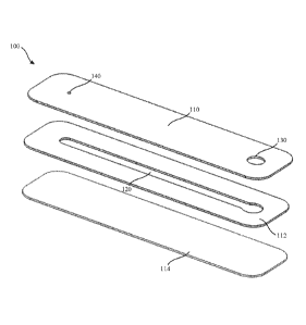
triple photosphate, mucus, sperm, combinations thereof, and the like.
[0036] FIG. 1A is an exploded perspective view of an illustrative example of a
microfluidic
device (100), according to some embodiments. The microfluidic device (100) may
include a first
layer (110) (e.g., cover, top portion) including a first opening (130) (e.g.,
proximal opening) and
a second opening (140) (e.g., distal opening), a second layer (112) (e.g.,
channel layer, middle
portion) including a microfluidic channel (120), and a third layer (114)
(e.g., base, substrate,
bottom portion). In some embodiments, each of the layers (110, 112, 114) may
generally form
an elongate rectangular structure where the layers may be configured to be
assembled one on top
of the other into a unitary structure, as shown in FIG. 1B. The first layer
(110) may be
substantially transparent while at least a portion of the second layer (112)
may be substantially
opaque. As used herein, transparency may include light transmission of about
10% or more
8
CA 03057501 2019-09-20
WO 2018/195530 PCT/US2018/028855
through a substrate while opaqueness may include light transmission of about
10% or less
through the substrate. For example, acrylic may be considered transparent as
it provides about
90% UV wavelength transmission. Most plastics are transparent and plastics
that may be formed
using laser welding may retain their transparency. In the assembled
configuration of FIG. 1B,
the microfluidic channel (120) may be coupled between the first opening (130)
and the second
opening (140). The second layer (112) may be coupled to the first layer (110)
such that the
microfluidic channel establishes a fluid communication path between the first
opening (130) and
the second opening (140). In some embodiments, the microfluidic device (100)
may have a
length of between about 1 mm and about 100 mm, a width of between about 1 mm
and about 50
mm, and a thickness of between about 1 mm and about 10 mm, including all
values and sub
ranges in-between.
[0037] The device (100) may include a transparent portion along a length of
the microfluidic
channel (120). The transparent portion may be configured to provide high
transmission and
minimal birefringence. As a practical matter, birefringence is always present
due to residual
stress and cannot be eliminated completely. For example, the transparent
portion may include
the microfluidic channel (120) of the second layer (112) and the regions of
the first layer (110)
and the third layer (114) overlying (i.e., directly above and below) the
microfluidic channel
(120). However, the transparent portion need not necessarily be perpendicular
to a plane of the
microfluidic device so long as a light beam may pass through the microfluidic
channel (120) and
be received by a detector (e.g., optical sensor). The transparent portion may
be substantially
transparent to at least one of ultraviolet light, visible light, and near-
infrared light. In some
embodiments, one or more additional regions of the device (100) may be
transparent. As another
example, substantially the entire device (100) may be transparent. The device
(100) may be
formed by, for example, one or more of acrylic, polycarbonate, cyclic olefin
copolymers (COC),
and polyester.
[0038] In some embodiments, the device (100) may be formed out of a
transparent polymer
such as acrylic, polycarbonate, combinations thereof, and the like. In some
embodiments, the
device (100) may include between about 0.01% to about 1.0% by weight of at
least one of
carbon black and a laser absorbing dye. For example, the second layer (112)
may include
9
CA 03057501 2019-09-20
WO 2018/195530 PCT/US2018/028855
between about 0.1% to about 1.0% by weight or between about 0.2% to about 0.3%
by weight of
at least one of carbon black and a laser absorbing dye. In some embodiments,
the microfluidic
channel (120) may be formed using low surface energy plastics such as
polycarbonate, COC,
and polyester that may enhance hydrophilic properties of the microfluidic
channel (120).
Additionally or alternatively, the microfluidic channel (120) may undergo
hydrophilic treatment
to enhance capillary fill in order to increase the surface energy and
wettability of the sample. For
example, microfluidic channels can be plasma etched using oxygen plasma.
Alternatively,
hydrophilic polymer (e.g., PVP, PEG, surfactant) coatings can be applied to
the microfluidic
channels using coating solutions, or chemical vapor deposition. In some
embodiments, one or
more substances (e.g., reagent) may be disposed in the microfluidic channel to
facilitate sample
analysis. For example, the reagents may include ly-sing agents and/or contrast
agents. Lysing
agents may lyse specific cell types such as red blood cells. Contrast agents
(e.g., staining agents)
may include nuclear, cytoplasm, and mitochondria (e.g., antibody and antibody
conjugates
including fluorescent dyes) corresponding to specific cellular antigens. For
example, one or
more substances may be disposed at specific regions of the microfluidic
channel (120) (e.g.,
proximal end) or throughout a length of the microfluidic channel (120).
[0039] In some embodiments, the first layer (110) may cover one side of the
microfluidic
channel (120) when assembled as shown in FIG. 1B. The first layer (110) may
have the same or
different thickness as the second layer (112) and/or third layer (114). Each
layer may have a
thickness between about 25 gm and 2 mm. For example, each layer may have a
thickness
between about 25 gm and about 1 mm. In FIGS. 1A-1B. each layer has a
substantially equal
thickness. The plane formed by the first layer (110) may correspond to a first
longitudinal side of
the device (100) while a plane formed by the third layer (114) may correspond
to a second
longitudinal side of the device (100). The first and second longitudinal sides
may be provided on
opposite sides of the second layer (112). In FIG. 1B, the microfluidic channel
(120) may be
about equidistant to the first longitudinal side and the second longitudinal
side. That is, the
microfluidic channel (120) may be defined along a central longitudinal plane
of the apparatus.
The microfluidic channel (120) may be arranged substantially parallel to the
first longitudinal
side.
CA 03057501 2019-09-20
WO 2018/195530 PCT/US2018/028855
[0040] In some embodiments, the microfluidic channel (120) of the second layer
(112) may
have a length of between about 1 mm and about 50 mm, a depth of between about
50 gm and
about 5000 gm, and a width of between about 50 gm and about 5000 gm. In FIG.
1B, the
microfluidic channel (120) may be linear relative to a longitudinal axis (102)
of the microfluidic
device (100). However, in other variations, the microfluidic channel (120) may
be curved
relative to a longitudinal axis (102) of the microfluidic device (100). For
example, the
microfluidic channel (120) may have a generally serpentine shape.
[0041] The first opening (130) of the first laver (110) may be configured to
receive a sample,
such as from a pipette. The first opening (130) may have any suitable shape
and/or size to
receive the sample. In FIGS. 1A-1B, the first opening (130) may be provided at
a proximal end
of the device (100) and may be fluidically connected to a first end of the
microfluidic channel
(120). In some embodiments, the first opening (130) may have a diameter of
between about
5000 gm and about 2 mm.
[0042] The second opening (140) of the first layer (110) may include an outlet
(e.g., vent)
configured to naturally vent gas (e.g., air) as the microfluidic channel (120)
is filled with a fluid.
In FIGS. 1A-1B, the second opening (140) may be provided at a distal end of
the device (100)
and may be fluidically connected to a second end of the microfluidic channel
(120). In some
embodiments, the second opening (140) may have a diameter of between about 10
gm and about
50 gm. In some embodiments, the first opening (130) and the second opening
(140) may be
spaced apart by between about 1 mm and about 100 mm. As shown in FIGS. 1A-1B,
the first
opening (130) may be larger than the second opening (140). Although FIGS. 1A-
1B illustrate a
single first opening (130) and a single second opening (140), the microfluidic
device (100) may
have a set of first openings (130) and a set of second openings (140).
[0043] In some embodiments, the microfluidic device (100) may include a set of
fiducials (not
shown) that may be imaged and/or otherwise detected by an optical detector of
a biofluid
analysis system. For example, a set of fiducials (e.g., colored/opaque points,
ruler, slits,
landmarks, markers) may be disposed at predetermined intervals along a length
of the
microfluidic channel (120) to aid image analysis. In some embodiments, the
microfluidic
11
CA 03057501 2019-09-20
WO 2018/195530 PCT/US2018/028855
channel (120) may include one or more filters (not shown) configured to
separate analvtes within
the sample based on size.
[0044] Although the device (100) shown in FIGS. IA-1B includes three layers,
it should be
appreciated that the microfluidic device (100) may be formed using more or
less layers. In some
embodiments, the device (100) may include a generally curved portion, as
described in more
detail with respect to FIG. 9, where a set of microfluidic channels may follow
a curved shape of
a housing.
[0045] In some embodiments, the third layer (114) and the second layer (120)
may be formed
using a die cut extruded film, and the first layer (11) may be formed using
injection molding. In
some embodiments, the second layer (112) may be bonded to the first layer
(110) and third layer
(114) using one or more of ultrasonic welding, laser welding, adhesives,
and/or solvent bonding.
[0046] As described in more detail herein, the microfluidic device (100) may
be coupled to a
microfluidic device case (e.g., sample holder, consumable, disposable) to aid
in one or more of
handling, tracking, and identification of a sample applied to the microfluidic
device. For
example, the microfluidic device case may include a grip portion for a user to
grasp without
touching the microfluidic device and potentially affecting the optical
qualities of the microfluidic
device. The microfluidic device case may be configured to hold the
microfluidic device at a
fixed position relative to the microfluidic device case.
[0047] In some embodiments, a third layer (114) of the microfluidic device
(100) may be
placed on a flat, horizontal surface to permit a sample (not shown) to be
input into the
microfluidic channel (120) through the first opening (130) (e.g., sample port,
biofluid input).
The sample may include, but is not limited to. urine, whole blood, plasma,
serum, combinations
thereof, and the like. The sample may flow through the microfluidic channel
(120) using
capillary action from a proximal to distal end of the microfluidic channel
(120). As the
microfluidic channel (120) fills with sample, gas (e.g., air) within the
microfluidic channel may
vent from the microfluidic device (100) through the second opening (140). In
some
embodiments, the first opening (130) may be coupled to at least one micropump
configured to
supply a continuous flow of the sample to the microfluidic device (100).
12
CA 03057501 2019-09-20
WO 2018/195530 PCT/US2018/028855
[0048] In some embodiments, the sample may be detected (e.g., imaged) as the
microfluidic
channel (120) is being filled and/or after a predetermined amount of time. For
example, analytes
(e.g., sediments, particulate matter) of the sample having a specific gravity
greater than one may
be allowed to settle within the microfluidic channel (120) over one or more
regions of the third
layer (114). This may aid image analysis of the sample so long as particle
concentration of the
sample is dilute enough to avoid superimposed particles. In some embodiments,
analysis (e.g.,
image analysis) of a sample having high particle concentration, may be
performed before one or
more analytes settle within the microfluidic channel (120). For example,
analytes including red
blood cells, platelets, white blood cells, and uric acid may be analyzed. Red
blood cells may
have a concentration of about 5 teracells/L, platelets may have a
concentration of about 0.3
teracells/L, white blood cells may have a concentration of about 7
gigacells/L, and uric acid may
have a concentration of about 100 moll. In some embodiments, a single
particle may be
analyzed in a sample, such as a single crystal. Additionally or alternatively,
ultrasonic vibration
may be applied to the microfluidic device (100) periodically to reduce
settling and maintain
suspension of one or more analytes.
[0049] In some embodiments, the microfluidic device (100) may be disposed
between a
radiation source and an optical detector. For example, the sample may be
imaged using a
radiation source facing an exposed side of the first layer (110) and an
optical detector facing the
exposed side of the third layer (114). As described in more detail herein,
detector data may be
used to generate analyte data that may be used to identify one or more
analytes and/or sample
attributes including, but not limited to, refractive index and osmolality.
[0050] FIG. 2A is an exploded perspective view of an illustrative example of a
microfluidic
device (200), according to some embodiments. The microfluidic device (200) may
include a first
layer (210) (e.g., cover, top portion) including a first opening (230) (e.g.,
proximal opening) and
a set of second openings (240) (e.g., distal opening), a second layer (212)
(e.g., channel layer,
middle portion) including a set of microfluidic channels (220), and a third
layer (214) (e.g., base,
substrate, bottom portion). In some embodiments, each of the layers (210, 212,
214) may
generally form an elongate rectangular structure where the layers may be
configured to be
assembled one on top of the other into a unitary structure, as shown in FIG.
2B. The first layer
13
CA 03057501 2019-09-20
WO 2018/195530 PCT/US2018/028855
(210) may be substantially transparent while at least a portion of the second
layer (112) may be
substantially opaque. In the assembled configuration of FIG. 2B, the set of
microfluidic channels
(220) may be coupled between the first opening (230) and the set of second
openings (240). The
set of microfluidic channels (220) may include a first channel, second
channel, and third channel
of a set of channels (220). The set of second openings (240) may include a
first opening, second
opening, and third opening of a set of openings (240). The second layer (112)
may be coupled to
the first layer (110) such that the microfluidic channel (220) establishes a
fluid communication
path between the first opening (230) and the second opening (240). In FIGS. 2A-
2B, the set of
microfluidic channels (220) may include three parallel channels, although more
or less channels
may be provided. This allows for separation of the sample and/or parallel
analysis of the sample.
For example, a first reagent and a second reagent may be disposed in
respective microfluidic
channels (220) to facilitate analysis of different analytes of the sample.
Additionally or
alternatively, identical parallel channels may improve a quality of sample
analysis. In some
embodiments, the microfluidic device (210) may have a length of between about
1 mm and
about 100 mm, a width of between about 1 mm and about 50 mm, and a thickness
of between
about 1 mm and about 10 mm.
[0051] The device (200) may include a transparent portion along a length of
the set of
microfluidic channels (220). The transparent portion may be configured to
provide high
transmission and minimal birefringence. For example, the transparent portion
may include the
set of microfluidic channels (220) of the second layer (212) and the regions
of the first layer
(210) and the third laver (214) overlying (i.e., directly above and below) the
set of microfluidic
channels (220). However, the transparent portion need not necessarily be
perpendicular to a
plane of the microfluidic device so long as a light beam may pass through the
set of microfluidic
channels (220) and be received by a detector (e.g., optical sensor). The
transparent portion may
be substantially transparent to at least one of ultraviolet light, visible
light, and near-infrared
light. In some embodiments, one or more additional regions of the device (200)
may be
transparent. As another example, substantially the entire device (200) may be
transparent. The
device (200) may be formed by, for example, one or more of acrylic,
polycarbonate, cyclic
olefin copolymers (COC), and polyester.
14
CA 03057501 2019-09-20
WO 2018/195530 PCT/US2018/028855
[0052] In some embodiments, the device (200) may be formed out of a
transparent polymer
such as acrylic, polycarbonate, combinations thereof, and the like. In some
embodiments, the
device (200) may include between about 0.01% to about 1.0% by weight of at
least one of
carbon black and a laser absorbing dye. For example, a layer may include
between about 0.1% to
about 1.0% by weight or between about 0.2% to about 0.3% by weight of at least
one of carbon
black and a laser absorbing dye. In some embodiments, the set of microfluidic
channel (220)
may be formed using low surface energy plastics such as polycarbonate, COC,
and polyester that
may enhance hydrophilic properties of the set of microfluidic channels (220).
Additionally or
alternatively, one or more of the set of microfluidic channels (220) may
undergo hydrophilic
treatment to enhance capillary fill in order to increase the surface energy
and wettability of the
sample. For example, hydrophilic polymers (e.g., PVP, PEG, surfactant) may be
applied to
microfluidic channel using plasma-etched vapor deposition (e.g., chemical). In
some
embodiments, one or more substances (e.g., reagent) may be disposed in the set
of microfluidic
channels (220) to facilitate sample analysis. For example, the reagents may
include lysing agents
and/or contrast agents. Lysing agents may lyse specific cell types such as red
blood cells.
Contrast agents (e.g., staining agents) may include nuclear, cytoplasm, and
mitochondria (e.g.,
antibody and antibody conjugates including fluorescent dyes) corresponding to
specific cellular
antigens. For example, one or more substances may be disposed at specific
regions of the set of
microfluidic channels (220) (e.g., proximal end) or throughout a length of the
set of microfluidic
channels (220).
[0053] In some embodiments, the first layer (210) may cover one side of the
set of
microfluidic channels (220) when assembled as shown in FIG. 2B. The first
layer (210) may
have the same or different thickness as the second layer (212) and/or third
layer (214). In FIGS.
2A-2B, each layer has a substantially equal thickness. Each layer may have a
thickness between
about 25 gm and 2 mm. For example, each layer may have a thickness between
about 25 gm and
about 1 mm. The plane formed by the first layer (210) may correspond to a
first longitudinal side
of the device (200) while a plane formed by the third layer (214) may
correspond to a second
longitudinal side of the device (200). The first and second longitudinal sides
may be provided on
opposite sides of the second layer (212). In FIG. 2B, the set of microfluidic
channels (220) may
be about equidistant to the first longitudinal side and the second
longitudinal side. That is, the
CA 03057501 2019-09-20
WO 2018/195530 PCT/US2018/028855
microfluidic channel (220) may be defined along a central longitudinal plane
of the apparatus.
The set of microfluidic channels (220) may be arranged substantially parallel
to the first
longitudinal side.
[0054] In some embodiments, the set of microfluidic channels (120) of the
second layer (212)
may have a length of between about 1 mm and about 50 mm, a depth of between
about 50 gm
and about 5000 gm, and a width of between about 50 gm and about 5000 gm. In
FIG. 2B, the
microfluidic channel (220) may be linear relative to a longitudinal axis (202)
of the microfluidic
device (200). However, the microfluidic channel (220) may be curved relative
to a longitudinal
axis (202) of the microfluidic device (200). For example, the microfluidic
channel (220) may
have a generally serpentine shape.
[0055] The first opening (230) of the first layer (210) may be configured to
receive a sample,
such as from a pipette. The first opening (230) may include any suitable shape
and/or size to
receive the sample. In FIGS. 2A-2B, the first opening (230) may be provided at
a proximal end
of the device (200) and may be fluidically connected to a first end of the set
of microfluidic
channels (220). In some embodiments, the first opening (230) may have a
diameter of between
about 5000 pm and about 2 mm.
[0056] The set of second openings (240) of the first layer (210) may include
an outlet (e.g.,
vent) configured to naturally vent gas (e.g., air) as the set of microfluidic
channels (220) are
filled with a fluid. In FIGS. 2A-2B, the set of second openings (240) may be
provided at a distal
end of the housing (2102) and may be fluidically connected to a second end of
the microfluidic
channel (220). In some embodiments, the set of second openings (240) may have
a diameter of
between about 10 gm and about 50 gm. In some embodiments, the first opening
(230) and the
set of second openings (240) may be spaced apart by between about 1 mm and
about 100 mm.
Although FIGS. 2A-2B illustrate a single first opening (230), the microfluidic
device (100) may
include a set of first openings (230) and a set of second openings (240).
[0057] In some embodiments, the microfluidic device (200) may include a set of
fiducials (not
shown) that may be imaged and/or otherwise detected by an optical detector of
a biofluid
analysis system. For example, a set of fiducials may be disposed at
predetermined intervals
16
CA 03057501 2019-09-20
WO 2018/195530 PCT/US2018/028855
along a length of the set of microfluidic channels (220) to aid image
analysis. In some
embodiments, the microfluidic channel (220) may include one or more filters
(not shown)
configured to separate analytes within the sample based on size.
[0058] Although the device (200) shown in FIGS. 2A-2B includes three layers,
it should be
appreciated that the microfluidic device (200) may be formed using more or
less layers. In some
embodiments, the device (200) may include a generally curved portion, as
described in more
detail with respect to FIG. 9, where a set of microfluidic channels may follow
a curved shape of
a housing.
[0059] In some embodiments, the third layer (214) and the second layer (212)
may be formed
using a die cut extruded film, and the first layer (210) may be formed using
injection molding. In
some embodiments, the second layer (212) may be bonded to the first layer
(210) and third layer
(214) using one or more of ultrasonic welding, laser welding, adhesives,
and/or solvent bonding.
[0060] As described in more detail herein, the microfluidic device (200) may
be coupled to a
microfluidic device case (e.g., sample holder, consumable, disposable) to aid
in one or more of
handling, tracking, and identification of a sample applied to the microfluidic
device. For
example, the microfluidic device case may include a grip portion for a user to
grasp without
touching the microfluidic device and potentially affecting the optical
qualities of the microfluidic
device. The microfluidic device case may be configured to hold the
microfluidic device at a
fixed position relative to the microfluidic device case
[0061] In some embodiments, a third layer (214) of the microfluidic device
(200) may be
placed on a flat, horizontal surface to permit a sample (not shown) to be
input into the
microfluidic channel (220) through the first opening (230) (e.g., sample port,
biofluid input).
The sample may include, but is not limited to, urine, whole blood, plasma,
serum, combinations
thereof, and the like. The sample may flow through the microfluidic channel
(220) using
capillary action from a proximal end to distal end of the microfluidic channel
(220). As the
microfluidic channel (220) fills with sample, gas (e.g., air) within the
microfluidic channel may
vent from the microfluidic device (200) through the set of second openings
(240). In some
17
CA 03057501 2019-09-20
WO 2018/195530 PCT/US2018/028855
embodiments, the first opening (230) may be coupled to at least one micropump
configured to
supply a continuous flow of the sample to the microfluidic device (200).
[0062] In some embodiments, the sample may be detected (e.g., imaged) as the
microfluidic
channel (220) is being filled and/or after a predetermined amount of time. For
example, analytes
(e.g., sediments, particulate matter) of the sample having a specific gravity
greater than one may
be allowed to settle within the microfluidic channel (220) over one or more
regions of the third
layer (214). This may aid image analysis of the sample so long as particle
concentration of the
sample is dilute enough to avoid superimposed particles. In some embodiments.
analysis (e.g.,
image analysis) of a sample having high particle concentration, may be
performed before one or
more analytes settle within the microfluidic channel (220). For example,
analytes including red
blood cells, platelets, white blood cells, and uric acid may be analyzed. Red
blood cells may
have a concentration of about 5 teracells/L, platelets may have a
concentration of about 0.3
teracells/L, white blood cells may have a concentration of about 7
gigacells/L, and uric acid may
have a concentration of about 100 [imol/L. In some embodiments, a single
particle may be
analyzed in a sample, such as a single crystal. Additionally or alternatively,
ultrasonic vibration
may be applied to the microfluidic device (200) periodically to reduce
settling and maintain
suspension of one or more analytes.
[0063] In some embodiments, the microfluidic device (200) may be disposed
between a
radiation source and a optical detector. For example, the sample may be imaged
using a radiation
source facing an exposed side of the first layer (210) and an optical detector
facing an exposed
side of the third layer (214). As described in more detail herein, detector
data may be used to
generate analyte data that may be used to identify one or more analytes and/or
sample attributes
including, but not limited to, refractive index and osmolality.
[0064] FIG. 3A is an exploded perspective view of an illustrative example of a
microfluidic
device (300), according to some embodiments. The microfluidic device (300) may
include a first
layer (310) (e.g., channel layer, top portion, cover) including a microfluidic
channel (320), a first
opening (330) (e.g., proximal opening), and a second opening (340) (e.g.,
distal opening) and a
second laver (312) (e.g., base, substrate, bottom portion). In some
embodiments, each of the
18
CA 03057501 2019-09-20
WO 2018/195530 PCT/US2018/028855
layers (310, 312) may generally form an elongate rectangular structure where
the layers may be
configured to be assembled one on top of the other into a unitary structure,
as shown in FIG. 3B.
The first layer (310) or the second layer (320) may be substantially
transparent while the other of
at least a portion of the second layer (312) and first layer (310) may be
substantially opaque. In
the assembled configuration of FIG. 3B, the microfluidic channel (320) may be
coupled between
the first opening (330) and the second opening (340). The second layer (312)
may be coupled to
the first layer (310) such that the microfluidic channel establishes a fluid
communication path
between the first opening (330) and the second opening (340). In some
embodiments, the
microfluidic device (300) may have a length of between about 1 mm and about
100 mm, a width
of between about 1 mm and about 50 mm, and a thickness of between about 1 mm
and about 10
mm.
[0065] The device (300) may include a transparent portion along a length of
the microfluidic
channel (320). The transparent portion may be configured to provide high
transmission and
minimal birefringence. For example, the transparent portion may include the
microfluidic
channel (320) of the first layer (310) and the regions of the second layer
(312) overlying (i.e.,
directly below) the microfluidic channel (320). However, the transparent
portion need not
necessarily be perpendicular to a plane of the microfluidic device so long as
a light beam may
pass through the microfluidic channel (320) and be received by a detector
(e.g., optical sensor).
The transparent portion may be substantially transparent to at least one of
ultraviolet light,
visible light, and near-infrared light. In some embodiments, one or more
additional regions of
the device (300) may be transparent. As another example, substantially the
entire device (300)
may be transparent. The device (300) may be formed by, for example, one or
more of acrylic,
polycarbonate, cyclic olefin copolymers (COC), and polyester.
[0066] In some embodiments, the device (300) may be formed out of a
transparent polymer
such as acrylic, polycarbonate, combinations thereof, and the like. In some
embodiments, the
device (300) may include between about 0.01% to about 1.0% by weight of at
least one of
carbon black and a laser absorbing dye. For example, the second layer may
include between
about 0.1% to about 1.0% by weight or between about 0.2% to about 0.3% by
weight of at least
one of carbon black and a laser absorbing dye. In some embodiments, the
microfluidic channel
19
CA 03057501 2019-09-20
WO 2018/195530 PCT/US2018/028855
(320) may be formed using low surface energy plastics such as polycarbonate,
COC, and
polyester that may enhance hydrophilic properties of the microfluidic channel
(320).
Additionally or alternatively, the microfluidic channel (320) may undergo
hydrophilic treatment
to enhance capillary fill in order to increase the surface energy and
wettability of the sample. For
example, hydrophilic polymers (e.g., PVP, PEG, surfactant) may be applied to
microfluidic
channel using plasma-etched vapor deposition (e.g., chemical). In some
embodiments, one or
more substances (e.g., reagent) may be disposed in the microfluidic channel
(320) to facilitate
sample analysis. For example, the reagents may include lysing agents and/or
contrast agents.
Lysing agents may lyse specific cell types such as red blood cells. Contrast
agents (e.g., staining
agents) may include nuclear, cytoplasm, and mitochondria (e.g., antibody and
antibody
conjugates including fluorescent dyes) corresponding to specific cellular
antigens. For example,
one or more substances may be disposed at specific regions of the microfluidic
channel (320)
(e.g., proximal end) or throughout a length of the microfluidic channel (320).
[0067] In some embodiments, the first layer (310) may cover one side of the
microfluidic
channel (320) when assembled as shown in FIG. 3B. The first layer (310) may
have a different
thickness than the second layer (312). The first layer (310) may have a
thickness between about
0.5 mm and about 2 mm and the second layer (312) may have a thickness between
about 25 um
and about 0.5 mm. In FIGS. 3A-3B, the second layer (312) is thinner than the
first layer (310).
In FIG. 3B, the microfluidic channel (320) may be closer to the second layer
(312) than an inlet
of the first and second openings (330, 340). The microfluidic channel (320)
may be arranged
substantially parallel to a plane of the first layer (310) and/or parallel and
offset from a central
longitudinal plane of the microfluidic device (300).
[0068] In some embodiments, the microfluidic channel (320) of the first layer
(310) may have
a length of between about 1 mm and about 50 mm, a depth of between about 50
p.m and about
5000 p.m, and a width of between about 50 p.m and about 5000 p.m. In FIG. 3B,
the microfluidic
channel (320) may be linear relative to a longitudinal axis (302) of the
microfluidic device (300).
However, in other variations, the microfluidic channel (320) may be curved
relative to a
longitudinal axis (302) of the microfluidic device (300). For example, the
microfluidic channel
(320) may include a generally serpentine shape.
CA 03057501 2019-09-20
WO 2018/195530 PCT/US2018/028855
[0069] The first opening (330) of the first layer (310) may be configured to
receive a sample,
such as from a pipette. The first opening (330) may include any suitable shape
and/or size to
receive the sample. In FIGS. 3A-3B, the first opening (330) may be provided at
a proximal end
of the device (300) and may be fluidically connected to a first end of the
microfluidic channel
(320). In some embodiments, the first opening (330) may have a diameter of
between about
5000 gm and about 2 mm.
[0070] The second opening (340) of the second layer (312) may include an
outlet (e.g., vent)
configured to naturally vent gas (e.g., air) as the microfluidic channel (320)
is filled with a fluid.
In FIGS. 3A-3B, the second opening (340) may be provided at a distal end of
the device (300)
and may be fluidically connected to a second end of the microfluidic channel
(320). In some
embodiments, the second opening (340) may have a diameter of between about 10
gm and about
50 gm. In some embodiments, the first opening (330) and the second opening
(340) may be
spaced apart by between about 1 mm and about 100 mm. Although FIGS. 3A-3B
illustrate a
single first opening (330) and a single second opening (340), the microfluidic
device (300) may
include a set of first openings (330) and a set of second openings (340).
[0071] In some embodiments, the microfluidic device (300) may include a set of
fiducials (not
shown) that may be imaged and/or otherwise detected by an optical detector of
a biofluid
analysis system. For example, a set of fiducials (e.g., colored/opaque points,
ruler, slits,
landmarks, markers) may be disposed at predetermined intervals along a length
of the
microfluidic channel (320) to aid image analysis. In some embodiments, the
microfluidic
channel (320) may include one or more filters (not shown) configured to
separate analytes within
the sample based on size.
[0072] Although the device (300) shown in FIGS. 3A-3B includes two layers, it
should be
appreciated that the microfluidic device (300) may be formed using more or
less layers. In some
embodiments, the device (300) may include a generally curved portion, as
described in more
detail with respect to FIG. 9, where a set of microfluidic channels may follow
a curved shape of
a housing.
21
CA 03057501 2019-09-20
WO 2018/195530 PCT/US2018/028855
[0073] In some embodiments, the first layer (310) and the second laver (320)
may be formed
using a die cut extruded film or injection molding. For example, the second
layer (312) may be
formed of a die cut extruded film while first layer (310) may be injection
molded. In some
embodiments, the second layer (312) may be bonded to the first layer (310)
using one or more of
ultrasonic welding, laser welding, adhesives, and/or solvent bonding.
[0074] As described in more detail herein, the microfluidic device (300) may
be coupled to a
microfluidic device case (e.g., sample holder, consumable, disposable) to aid
in one or more of
handling, tracking, and identification of a sample applied to the microfluidic
device. For
example, the microfluidic device case may include a grip portion for a user to
grasp without
touching the microfluidic device and potentially affecting the optical
qualities of the microfluidic
device. The microfluidic device case may be configured to hold the
microfluidic device at a
fixed position relative to the microfluidic device case
[0075] In some embodiments, a second layer (312) of the microfluidic device
(300) may be
placed on a flat, horizontal surface to permit a sample (not shown) to be
input into the
microfluidic channel (320) through the first opening (330) (e.g., sample port,
biofluid input).
The sample may include, but is not limited to, urine, whole blood, plasma,
serum, combinations
thereof, and the like. The sample may flow through the microfluidic channel
(320) using
capillary action from a proximal to distal end of the microfluidic channel
(320). As the
microfluidic channel (320) fills with sample, gas (e.g., air) within the
microfluidic channel may
vent from the microfluidic device (300) through the second opening (340). In
some
embodiments, the first opening (330) may be coupled to at least one micropump
configured to
supply a continuous flow of the sample to the microfluidic device (300).
[0076] In some embodiments, the sample may be detected (e.g., imaged) as the
microfluidic
channel (320) is being filled and/or after a predetermined amount of time. For
example, analytes
(e.g., sediments, particulate matter) of the sample having a specific gravity
greater than one may
be allowed to settle within the microfluidic channel (320) over one or more
regions of the second
layer (312). This may aid image analysis of the sample so long as particle
concentration of the
sample is dilute enough to avoid superimposed particles. In some embodiments,
analysis (e.g.,
22
CA 03057501 2019-09-20
WO 2018/195530 PCT/US2018/028855
image analysis) of a sample having high particle concentration, may be
performed before one or
more analytes settle within the microfluidic channel (320). For example,
analytes including red
blood cells, platelets, white blood cells, and uric acid may be analyzed. Red
blood cells may
have a concentration of about 5 teracells/L, platelets may have a
concentration of about 0.3
teracells/L, white blood cells may have a concentration of about 7
gigacells/L, and uric acid may
have a concentration of about 100 [imol/L. In some embodiments, a single
particle may be
analyzed in a sample, such as a single crystal. Additionally or alternatively,
ultrasonic vibration
may be applied to the microfluidic device (300) periodically to reduce
settling and maintain
suspension of one or more analytes.
[0077] In some embodiments, the microfluidic device (300) may be disposed
between a
radiation source and an optical detector. For example, the sample may be
imaged using a
radiation source facing an exposed side of the first layer (310) and an
optical detector facing an
exposed side of the second layer (312) such that the detector is closer to the
microfluidic channel
(320). As described in more detail herein, detector data may be used to
generate analyte data that
may be used to identify one or more analytes and/or sample attributes
including, but not limited
to, refractive index and osmolality.
[0078] FIG. 4A is an exploded perspective view of an illustrative example of a
microfluidic
device (400), according to some embodiments. The microfluidic device (400) may
include a first
layer (410) (e.g., top portion, cover) including a first opening (430) (e.g.,
proximal opening) and
a second opening (440) (e.g., distal opening) and a second layer (412) (e.g.,
base, channel layer,
substrate, bottom portion) including a microfluidic channel (420). In some
embodiments, each of
the layers (410, 412) may generally form an elongate rectangular structure
where the layers may
be configured to be assembled one on top of the other into a unitary
structure, as shown in FIG.
4B. The first layer (410) or the second layer (420) may be substantially
transparent while the
other of at least a portion of the second layer (412) or first layer (410) may
be substantially
opaque. In the assembled configuration of FIG. 4B, the microfluidic channel
(420) may be
coupled between the first opening (430) and the second opening (440). The
second layer (412)
may be coupled the first layer (410) such that the microfluidic channel (420)
establishes a fluid
communication path between the first opening (430) and the second opening
(440). In some
23
CA 03057501 2019-09-20
WO 2018/195530 PCT/US2018/028855
embodiments, the microfluidic device (400) may have a length of between about
1 mm and
about 100 mm, a width of between about 1 mm and about 50 mm, and a thickness
of between
about 1 mm and about 10 mm.
[0079] The device (400) may include a transparent portion along a length of
the microfluidic
channel (420). The transparent portion may be configured to provide high
transmission and
minimal birefringence. For example, the transparent portion may include the
microfluidic
channel (420) of the second layer (412) and the regions of the first layer
(410) overlying (i.e.,
directly above) the microfluidic channel (420). However, the transparent
portion need not
necessarily be perpendicular to a plane of the microfluidic device so long as
a light beam may
pass through the microfluidic channel (420) and be received by a detector
(e.g., optical sensor).
The transparent portion may be substantially transparent to at least one of
ultraviolet light,
visible light, and near-infrared light. In some embodiments, one or more
additional regions of
the device (400) may be transparent. As another example, substantially the
entire device (400)
may be transparent. The device (400) may be formed by, for example, one or
more of acrylic,
polycarbonate, cyclic olefin copolymers (COC), and polyester.
[0080] In some embodiments, the device (400) may be formed out of a
transparent polymer
such as acrylic, polycarbonate, combinations thereof and the like. In some
embodiments, the
device (400) may include between about 0.01% to about 1.0% by weight of at
least one of
carbon black and a laser absorbing dye. For example, a layer may include
between about 0.1% to
about 1.0% by weight or between about 0.2% to about 0.3% by weight of at least
one of carbon
black and a laser absorbing dye. In some embodiments, the microfluidic channel
(420) may be
formed using low surface energy plastics such as polycarbonate, COC, and
polyester that may
enhance hydrophilic properties of the microfluidic channel (420). Additionally
or alternatively,
the microfluidic channel (420) may undergo hydrophilic treatment to enhance
capillary fill in
order to increase the surface energy and wettability of the sample. For
example, hydrophilic
polymers (e.g., PVP, PEG, surfactant) may be applied to microfluidic channel
using plasma-
etched vapor deposition (e.g., chemical). In some embodiments, one or more
substances (e.g.,
reagent) may be disposed in the microfluidic channel to facilitate sample
analysis. For example,
the reagents may include lvsing agents and/or contrast agents. Lysing agents
may lyse specific
24
CA 03057501 2019-09-20
WO 2018/195530 PCT/US2018/028855
cell types such as red blood cells. Contrast agents (e.g., staining agents)
may include nuclear,
cytoplasm, and mitochondria (e.g., antibody and antibody conjugates including
fluorescent dyes)
corresponding to specific cellular antigens. For example, one or more
substances may be
disposed at specific regions of the microfluidic channel (420) (e.g., proximal
end) or throughout
a length of the microfluidic channel (420).
[0081] In some embodiments, the first layer (410) may cover one side of the
microfluidic
channel (420) when assembled as shown in FIG. 4B. The first layer (410) may
have a different
thickness than the second layer (412). The second layer (412) may have a
thickness between
about 0.5 mm and about 2 mm and the first layer (410) may have a thickness
between about 25
gm and about 0.5 mm. In FIGS. 4A-4B, the second layer (412) is thicker than
the first layer
(410). In FIG. 4B, the microfluidic channel (420) may be closer to the first
layer (410) than a
bottom surface of the second layer (412). The microfluidic channel (420) may
be arranged
substantially parallel to a plane of the first layer (410). That is, the
microfluidic channel (420)
may be parallel and offset from a central longitudinal plane of the apparatus.
[0082] In some embodiments, the microfluidic channel (420) of the first layer
(412) may have
a length of between about 1 mm and about 50 mm, a depth of between about 50 gm
and about
5000 gm, and a width of between about 50 gm and about 5000 gm. In FIG. 4B, the
microfluidic
channel (420) may be linear relative to a longitudinal axis (402) of the
microfluidic device (400).
However, in other variations, the microfluidic channel (420) may have be
curved relative to a
longitudinal axis (402) of the microfluidic device (400). For example, the
microfluidic channel
(420) may include a generally serpentine shape.
[0083] The first opening (430) of the first layer (410) may be configured to
receive a sample,
such as from a pipette. The first opening (430) may include any suitable shape
and/or size to
receive the sample. In FIGS. 4A-4B, the first opening (430) may be provided at
a proximal end
of the device (400) and may be fluidically connected to a first end of the
microfluidic channel
(420). In some embodiments, the first opening (430) may have a diameter of
between about
5000 gm and about 2 mm.
CA 03057501 2019-09-20
WO 2018/195530 PCT/US2018/028855
[0084] The second opening (440) of the first layer (410) may include an outlet
configured to
naturally vent gas (e.g., air) as the microfluidic channel (420) is filled
with a fluid. In FIGS. 4A-
4B, the second opening (440) may be provided at a distal end of the device
(400) and may be
fluidically connected to a second end of the microfluidic channel (420). In
some embodiments,
the second opening (440) may have a diameter of between about 10 gm and about
50 gm. In
some embodiments, the first opening (430) and the second opening (440) may be
spaced apart
by between about 1 mm and about 100 mm. Although FIGS. 4A-4B illustrate a
single first
opening (430) and a single second opening (440), the microfluidic device (400)
may include a
set of first openings (430) and a set of second openings (440).
[0085] In some embodiments, the microfluidic device (400) may include a set of
fiducials (not
shown) that may be imaged and/or otherwise detected by an optical detector of
a biofluid
analysis system. For example, a set of fiducials (e.g., colored/opaque points,
ruler, slits,
landmarks, markers) may be disposed at predetermined intervals along a length
of the
microfluidic channel (420) to aid image analysis. In some embodiments, the
microfluidic
channel (420) may include one or more filters (not shown) configured to
separate analytes within
the sample based on size.
[0086] Although the device (400) shown in FIGS. 4A-4B includes two layers, it
should be
appreciated that the microfluidic device (400) may be formed using more or
less layers. In some
embodiments, the device (400) may include a generally curved portion, as
described in more
detail with respect to FIG. 9, where a set of microfluidic channels may follow
a curved shape of
a housing.
[0087] In some embodiments, the first layer (410) and the second layer (420)
may be formed
using a die cut extruded film or injection molding. In some embodiments, the
second layer (412)
may be bonded to the first layer (410) using one or more of ultrasonic
welding, laser welding,
adhesives, and/or solvent bonding.
[0088] As described in more detail herein, the microfluidic device (400) may
be coupled to a
microfluidic device case (e.g., sample holder, consumable, disposable) to aid
in one or more of
handling, tracking, and identification of a sample applied to the microfluidic
device. For
26
CA 03057501 2019-09-20
WO 2018/195530 PCT/US2018/028855
example, the microfluidic device case may include a grip portion for a user to
grasp without
touching the microfluidic device and potentially affecting the optical
qualities of the microfluidic
device. The microfluidic device case may be configured to hold the
microfluidic device at a
fixed position relative to the microfluidic device case
[0089] In some embodiments, a second layer (412) of the microfluidic device
(400) may be
placed on a flat, horizontal surface to permit a sample (not shown) to be
input into the
microfluidic channel (420) through the first opening (430) (e.g., sample port,
biofluid input).
The sample may include, but is not limited to, urine, whole blood, plasma,
serum, combinations
thereof, and the like. The sample may flow through the microfluidic channel
(420) using
capillary action from a proximal to distal end of the microfluidic channel
(420). As the
microfluidic channel (420) fills with sample, gas (e.g., air) within the
microfluidic channel may
vent from the microfluidic device (400) through the second opening (440). In
some
embodiments, the first opening (430) may be coupled to at least one micropump
configured to
supply a continuous flow of the sample to the microfluidic device (400).
[0090] In some embodiments, the sample may be detected (e.g., imaged) as the
microfluidic
channel (420) is being filled and/or after a predetermined amount of time. For
example, analytes
(e.g., sediments, particulate matter) of the sample having a specific gravity
greater than one may
be allowed to settle within the microfluidic channel (420) over one or more
regions of the second
layer (412). This may aid image analysis of the sample so long as particle
concentration of the
sample is dilute enough to avoid superimposed particles. In some embodiments,
analysis (e.g.,
image analysis) of a sample having high particle concentration, may be
performed before one or
more analytes settle within the microfluidic channel (420). For example,
analytes including red
blood cells, platelets, white blood cells, and uric acid may be analyzed. Red
blood cells may
have a concentration of about 5 teracells/L. platelets may have a
concentration of about 0.3
teracells/L, white blood cells may have a concentration of about 7
gigacells/L, and uric acid may
have a concentration of about 100 moll. In some embodiments, a single
particle may be
analyzed in a sample, such as a single crystal. Additionally or alternatively,
ultrasonic vibration
may be applied to the microfluidic device (400) periodically to reduce
settling and maintain
suspension of one or more analytes.
27
CA 03057501 2019-09-20
WO 2018/195530 PCT/US2018/028855
[0091] In some embodiments, the microfluidic device (400) may be disposed
between a
radiation source and an optical detector. For example, the sample may be
imaged using a
radiation source facing an exposed side of the second layer (412) and an
optical detector facing
the exposed side of the first layer (410) such that the detector is closer to
the microfluidic
channel (420). As described in more detail herein, detector data may be used
to generate analyte
data that may be used to identify one or more analytes and/or sample
attributes including, but not
limited to, refractive index and osmolality.
[0092] FIG. 5A is an exploded perspective view of an illustrative example of a
microfluidic
device (500), according to some embodiments. The microfluidic device (500) may
include a first
layer (510) (e.g., channel layer, top portion, cover) including a set of
microfluidic channels
(520), a first opening (530) (e.g., proximal opening), and a set of second
openings (540) (e.g.,
distal opening) and a second layer (512) (e.g., base, substrate, bottom
portion). In some
embodiments, each of the layers (510, 512) may generally form an elongate
rectangular structure
where the layers may be configured to be assembled one on top of the other
into a unitary
structure, as shown in FIG. 5B. The first layer (510) or the second layer
(510) may be
substantially transparent while the other of at least a portion of the second
layer (512) or first
layer (510) may be substantially opaque. In the assembled configuration of
FIG. 5B, the set of
microfluidic channels (520) may be fluidically coupled to establish a fluid
communication path
between the first opening (530) and the set of second openings (540). The set
of microfluidic
channels (520) may include a first channel, second channel, and third channel
of a set of
channels (520). The set of second openings (540) may include a first opening,
second opening,
and third opening of a set of openings (540). In some embodiments, the
microfluidic device
(500) may have a length of between about 1 mm and about 100 mm, a width of
between about 1
mm and about 50 mm, and a thickness of between about 1 mm and about 10 mm.
[0093] The device (500) may include a transparent portion along a length of
the microfluidic
channels (520). The transparent portion may be configured to provide high
transmission and
minimal birefringence. For example, the transparent portion may include the
set of microfluidic
channel (520) of the second layer (512) and the regions of the first layer
(510) overlying (i.e.,
directly below) the set of microfluidic channels (520). However, the
transparent portion need not
28
CA 03057501 2019-09-20
WO 2018/195530 PCT/US2018/028855
necessarily be perpendicular to a plane of the microfluidic device so long as
a light beam may
pass through the set of microfluidic channels (520) and be received by a
detector (e.g., optical
sensor). The transparent portion may be substantially transparent to at least
one of ultraviolet
light, visible light, and near-infrared light. In some embodiments, one or
more additional regions
of the device (500) may be transparent. As another example, substantially the
entire device (500)
may be transparent. The device (500) may be formed by, for example, one or
more of acrylic,
polycarbonate, cyclic olefin copolymers (COC), and polyester.
[0094] In some embodiments, the device (500) may be formed out of a
transparent polymer
such as acrylic, poly-carbonate, combinations thereof, and the like. In some
embodiments, the
device (500) may include between about 0.01% to about 1.0% by weight of at
least one of
carbon black and a laser absorbing dye. For example, a layer may include
between about 0.1% to
about 1.0% by weight or between about 0.2% to about 0.3% by weight of at least
one of carbon
black and a laser absorbing dye. In some embodiments, the set of microfluidic
channels (520)
may be formed using low surface energy plastics such as polycarbonate, COC,
and polyester that
may enhance hydrophilic properties of the set of microfluidic channels (520).
Additionally or
alternatively, the set of microfluidic channels (520) may undergo hydrophilic
treatment to
enhance capillary fill in order to increase the surface energy and wettability
of the sample. For
example, hydrophilic polymers (e.g., PVP, PEG, surfactant) may be applied to
microfluidic
channel using plasma-etched vapor deposition (e.g., chemical). In some
embodiments, one or
more substances (e.g., reagent) may be disposed in each of the microfluidic
channels to facilitate
sample analysis. For example, the reagents may include lysing agents and/or
contrast agents.
Lysing agents may lyse specific cell types such as red blood cells. Contrast
agents (e.g., staining
agents) may include nuclear, cytoplasm, and mitochondria (e.g., antibody and
antibody
conjugates including fluorescent dyes) corresponding to specific cellular
antigens. For example,
one or more substances may be disposed at specific regions of the set of
microfluidic channels
(520) (e.g., proximal end) or throughout a length of the set of microfluidic
channels (520). A set
of microfluidic channels (520) allows a larger volume of biofluid to be
analyzed and allows
independent flow of biofluid through the set of microfluidic channels (520).
29
CA 03057501 2019-09-20
WO 2018/195530 PCT/US2018/028855
[0095] In some embodiments, the first layer (510) may cover one side of the
set of
microfluidic channels (520) when assembled as shown in FIG. 5B. The first
layer (510) may
have a different thickness than the second layer (512). In FIGS. 5A-5B, the
second layer (512) is
thicker than the first layer (510). The first layer (510) may have a thickness
between about 0.5
mm and about 2 mm and the second layer (512) may have a thickness between
about 25 gm and
about 0.5 mm. In FIG. 5B, the set of microfluidic channels (520) may be closer
to the first layer
(510) than an inlet of the first and second openings (530, 540). The set of
microfluidic channels
(520) may be arranged substantially parallel to a plane of the first layer
(510).
[0096] In some embodiments, the set of microfluidic channels (520) of the
second layer (512)
may have a length of between about 1 mm and about 50 mm, a depth of between
about 50 um
and about 5000 gm, and a width of between about 50 gm and about 5000 gm. In
FIG. 5B, the
set of microfluidic channels (520) may be linear. However, the set of
microfluidic channels
(520) may have one or more curved portions. For example, the set of
microfluidic channels
(520) may include a generally serpentine shape.
[0097] The first opening (530) of the second layer (512) may be configured to
receive a
sample, such as from a pipette. The first opening (530) may include any
suitable shape and/or
size to receive the sample. In FIGS. 5A-5B, the first opening (530) may be
provided at a
proximal end of the device (500) and may be fluidically connected to a first
end of the set of
microfluidic channels (520). In some embodiments, the first opening (530) may
have a diameter
of between about 5000 p.m and about 2 mm.
[0098] The set of second openings (540) of the second layer (512) may include
an outlet
configured to naturally vent gas (e.g., air) as the set of microfluidic
channels (520) is filled with
a fluid. In FIGS. 5A-5B, the second opening (540) may be provided at a distal
end of the device
(500) and may be fluidically connected to a second end of the set of
microfluidic channels (520).
In some embodiments, the set of second openings (540) may have a diameter of
between about
gm and about 50 gm. In some embodiments, the first opening (530) and the set
of second
openings (540) may be spaced apart by between about 1 mm and about 100 mm.
Although
FIGS. 5A-5B illustrate a single first opening (530) and a set of 3 second
openings (540), the
CA 03057501 2019-09-20
WO 2018/195530 PCT/US2018/028855
microfluidic device (500) may include a set of first openings (530) and a set
of second openings
(540).
[0099] In some embodiments, the microfluidic device (500) may include a set of
fiducials (not
shown) that may be imaged and/or otherwise detected by an optical detector of
a biofluid
analysis system. For example, a set of fiducials (e.g., colored/opaque points,
ruler, slits,
landmarks, markers) may be disposed at predetermined intervals along a length
of the set of
microfluidic channels (520) to aid image analysis. In some embodiments, the
set of microfluidic
channels (520) may include one or more filters (not shown) configured to
separate analytes
within the sample based on size.
[00100] Although the device (500) shown in FIGS. 5A-5B includes two layers, it
should be
appreciated that the microfluidic device (500) may be formed using more or
less layers. In some
embodiments, the device (500) may include a generally curved portion, as
described in more
detail with respect to FIG. 9, where a set of microfluidic channels may follow
a curved shape of
a housing.
[00101] In some embodiments, the first layer (510) and the second laver (512)
may be formed
using a die cut extruded film or injection molding. For example, the first
layer (510) may be
formed of a die cut extruded film while second layer (512) may be injection
molded. In some
embodiments, the second layer (512) may be bonded to the first layer (510)
using one or more of
ultrasonic welding, laser welding, adhesives, and/or solvent bonding.
[00102] As described in more detail herein, the microfluidic device (500) may
be coupled to a
microfluidic device case (e.g., sample holder, consumable, disposable) to aid
in one or more of
handling, tracking, and identification of a sample applied to the microfluidic
device. For
example, the microfluidic device case may include a grip portion for a user to
grasp without
touching the microfluidic device and potentially affecting the optical
qualities of the microfluidic
device. The microfluidic device case may be configured to hold the
microfluidic device at a
fixed position relative to the microfluidic device case
31
CA 03057501 2019-09-20
WO 2018/195530 PCT/1JS2018/028855
[00103] In some embodiments, a first layer (510) of the microfluidic device
(500) may be
placed on a flat, horizontal surface to permit a sample (not shown) to be
input into the set of
microfluidic channels (520) through the first opening (530) (e.g., sample
port, biofluid input).
The sample may include, but is not limited to, urine, whole blood, plasma,
serum, combinations
thereof, and the like. The sample may flow through the set of microfluidic
channels (520) using
capillary action from a proximal to distal end of the set of microfluidic
channels (520). As the set
of microfluidic channels (520) fills with sample, gas (e.g., air) within the
set of microfluidic
channels (520) may vent from the microfluidic device (500) through the second
opening (540).
In some embodiments, the first opening (530) may be coupled to at least one
micropump
configured to supply a continuous flow of the sample to the microfluidic
device (500).
[00104] In some embodiments, the sample may be detected (e.g., imaged) as the
set of
microfluidic channels (520) are being filled and/or after a predetermined
amount of time. For
example, analytes (e.g., sediments, particulate matter) of the sample having a
specific gravity
greater than one may be allowed to settle within the set of microfluidic
channels (520) over one
or more regions of the first layer (510). This may aid image analysis of the
sample so long as
particle concentration of the sample is dilute enough to avoid superimposed
particles. In some
embodiments, analysis (e.g., image analysis) of a sample having high particle
concentration,
may be performed before one or more analytes settle within the set of
microfluidic channels
(520). For example, analytes including red blood cells, platelets, white blood
cells, and uric acid
may be analyzed. Red blood cells may have a concentration of about 5
teracells/L, platelets may
have a concentration of about 0.3 teracells/L, white blood cells may have a
concentration of
about 7 gigacells/L, and uric acid may have a concentration of about 100 mon.
In some
embodiments, a single particle may be analyzed in a sample, such as a single
crystal.
Additionally or alternatively, ultrasonic vibration may be applied to the
microfluidic device
(500) periodically to reduce settling and maintain suspension of one or more
analytes.
[00105] In some embodiments, the microfluidic device (500) may be disposed
between the
radiation source and the optical detector. For example, the sample may be
imaged using a
radiation source facing an exposed side of the second layer (512) and an
optical detector facing
an exposed side of the first layer (510) such that the detector is closer to
the set of microfluidic
32
CA 03057501 2019-09-20
WO 2018/195530 PCT/US2018/028855
channels (520). As described in more detail herein, detector data may be used
to generate analyte
data that may be used to identify one or more analytes and/or sample
attributes including, but not
limited to, refractive index and osmolality. Although the set of microfluidic
channels (520)
shown in FIGS. 5A-5B includes three channels, it should be appreciated that
the microfluidic
device (500) may be formed using more or less channels.
[00106] FIG. 6A is an exploded perspective view of an illustrative example of
a microfluidic
device (600), according to some embodiments. The microfluidic device (600) may
include a first
layer (610) (e.g., channel layer, top portion, cover) including a microfluidic
channel (620)
including a set of step regions (620a, 620b, 620c) having a set of
corresponding heights, a first
opening (630) (e.g., proximal opening), and a second opening (640) (e.g.,
distal opening) and a
second layer (612) (e.g., base, substrate, bottom portion). In some
embodiments, each of the
layers (610, 612) may generally form an elongate rectangular structure where
the layers may be
configured to be assembled one on top of the other into a unitary structure,
as shown in FIG. 6B.
The first layer (610) or the second layer (612) may be substantially
transparent while the other of
at least a portion of the second layer (612) and first layer (610) may be
substantially opaque. In
the assembled configuration of FIG. 6B, the microfluidic channel (620) having
a set of step
regions (620a, 620b, 620c) may be coupled between the first opening (630) and
the second
opening (640). The second layer (612) may be coupled to the first layer (610)
such that the
microfluidic channel (620) establishes a fluid communication path between the
first opening
(630) and the second opening (640). In some embodiments, the microfluidic
device (600) may
have a length of between about 1 mm and about 100 mm, a width of between about
1 mm and
about 50 mm, and a thickness of between about 1 mm and about 10 mm.
[00107] As shown in FIGS. 6C-6D, the microfluidic channel (620) may define a
set of steps
(620a, 620b, 620c) such that a height of the microfluidic channel (620)
decreases in a step-wise
manner from the first opening (630) to the second opening (640). That is, a
volume of each step
may decrease from the first opening (630) to the second opening (640). In some
embodiments, a
height of each step of the set of steps (620a, 620b, 620c) may be from about
0.1 mm to about 0.9
mm. For example, a height of the first step (620a) may be about 0.9 mm, a
height of the second
step (620b) may be about 0.4 mm, and a height of the third step (620c) may be
about 0.1 mm.
33
CA 03057501 2019-09-20
WO 2018/195530 PCT/1JS2018/028855
[00108] The device (600) may include a transparent portion along a length of
the microfluidic
channel (620). The transparent portion may be configured to provide high
transmission and
minimal birefringence. For example, the transparent portion may include the
microfluidic
channel (620) of the first layer (610) and the regions of the second layer
(612) overlying (i.e.,
directly below) the microfluidic channel (620). However, the transparent
portion need not
necessarily be perpendicular to a plane of the microfluidic device so long as
a light beam may
pass through the microfluidic channel (620) and be received by a detector
(e.g., optical sensor).
The transparent portion may be substantially transparent to at least one of
ultraviolet light,
visible light, and near-infrared light. In some embodiments, one or more
additional regions of
the device (600) may be transparent. As another example, substantially the
entire device (600)
may be transparent. The device (600) may be formed by, for example, one or
more of acrylic,
polycarbonate, cyclic olefin copolymers (COC), and polyester.
[00109] In some embodiments, the device (600) may be formed out of a
transparent polymer
such as acrylic, poly carbonate, combinations thereof and the like. In some
embodiments, the
device (600) may include between about 0.01% to about 1.0% by weight of at
least one of
carbon black and a laser absorbing dye. For example, a layer may include
between about 0.1% to
about 1.0% by weight or between about 0.2% to about 0.3% by weight of at least
one of carbon
black and a laser absorbing dye. In some embodiments, the microfluidic channel
(620) may be
formed using low surface energy plastics such as polycarbonate, COC, and
polyester that may
enhance hydrophilic properties of the microfluidic channel (620). Additionally
or alternatively,
one or more regions (620a, 620b, 620c) of the microfluidic channel (620) may
undergo
hydrophilic treatment to enhance capillary fill in order to increase the
surface energy and
wettability of the sample. For example, hydrophilic polymers (e.g., PVP, PEG,
surfactant) may
be applied to microfluidic channel using plasma-etched vapor deposition (e.g.,
chemical). In
some embodiments, one or more substances (e.g., reagents) may be disposed in
one or more
regions of the microfluidic channel (620) to facilitate sample analysis. For
example, the reagents
may include lysing agents and/or contrast agents. Lysing agents may lyse
specific cell types such
as red blood cells. Contrast agents (e.g., staining agents) may include
nuclear, cytoplasm, and
mitochondria (e.g., antibody and antibody conjugates including fluorescent
dyes) corresponding
to specific cellular antigens. For example, one or more substances may be
disposed at specific
34
CA 03057501 2019-09-20
WO 2018/195530 PCT/US2018/028855
regions (620a, 620b, 620c) of the microfluidic channel (620) (e.g., proximal
end) or throughout a
length of the microfluidic channel (620).
[00110] In some embodiments, the second layer (612) may cover one side of the
microfluidic
channel (620) when assembled as shown in FIG. 6B. The first layer (610) may
have a different
thickness than the second layer (612). In FIGS. 6A-6B, the first layer (610)
is thicker than the
second layer (612). The first layer (610) may have a thickness between about
0.5 mm and about
2 mm and the second layer (612) may have a thickness between about 25 gm and
about 0.5 mm.
In FIG. 6B, the microfluidic channel (620) may decrease in height from the
first opening (630)
to the second opening (640). The microfluidic channel (620) may be arranged
substantially
parallel to a plane of the second layer (612).
[00111] In some embodiments, the microfluidic channel (620) of the first layer
(610) may have
a length of between about 1 mm and about 50 mm, a depth of between about 50 gm
and about
5000 gm, and a width of between about 50 gm and about 5000 gm. In FIG. 6B, the
microfluidic
channel (620) may be linear relative to a longitudinal axis (602) of the
microfluidic device (100).
However, in other variations, the microfluidic channel (620) may be curved
relative to a
longitudinal axis (602) of the microfluidic device (600). For example, the
microfluidic channel
(620) may include a generally serpentine shape. The regions (620a, 620b, 620c)
of the
microfluidic channel (620) may include about the same length or have different
lengths. The first
region (620a) may have a height about three times that of the third region
(620c) and the second
region (620b) may have a height about three times that of the third region
(620c). The
microfluidic channel (620) may have a constant width or may have a width that
varies per region
(620a, 620b, 620c).
[00112] The first opening (630) of the first layer (610) may be configured to
receive a sample,
such as from a pipette. The first opening (630) may include any suitable shape
and/or size to
receive the sample. In FIGS. 6A-6B, the first opening (630) may be provided at
a proximal end
of the device (600) and may be fluidically connected to a first end of the
microfluidic channel
(620). In some embodiments, the first opening (630) may have a diameter of
between about
5000 gm and about 2 mm.
CA 03057501 2019-09-20
WO 2018/195530 PCT/US2018/028855
[00113] The second opening (640) of the first layer (610) may include an
outlet configured to
naturally vent gas (e.g., air) as the microfluidic channel (620) is filled
with a fluid. In FIGS. 6A-
613, the second opening (640) may be provided at a distal end of the device
(600) and may be
fluidically connected to a second end of the microfluidic channel (620). In
some embodiments,
the second opening (640) may have a diameter of between about 10 gm and about
50 gm. In
some embodiments, the first opening (630) and the second opening (640) may be
spaced apart
by between about 1 mm and about 100 mm. Although FIGS. 6A-6B illustrate a
single first
opening (630) and a single second opening (640), the microfluidic device (600)
may include a
set of first openings (630) and a set of second openings (640).
[00114] In some embodiments, the microfluidic device (600) may include a set
of fiducials (not
shown) that may be imaged and/or otherwise detected by an optical detector of
a biofluid
analysis system. For example, a set of fiducials (e.g., colored/opaque points,
ruler, slits,
landmarks, markers) may be disposed at predetermined intervals along a length
of the
microfluidic channel (620) to aid image analysis. For example, each region
(620a, 620b, 620c)
of the microfluidic channel (620) may include a corresponding fiducial. In
some embodiments,
the microfluidic channel (620) may include one or more filters (not shown)
configured to
separate analytes within the sample based on size. For example, a filter may
be provided
between each region (620a, 620b, 620c) of the microfluidic channel (620).
[00115] Although the device (600) shown in FIGS. 6A-6B includes two layers, it
should be
appreciated that the microfluidic device (600) may be formed using more or
less layers. In some
embodiments, the device (600) may include a generally curved portion, as
described in more
detail with respect to FIG. 9, where a set of microfluidic channels may follow
a curved shape of
a housing.
[00116] In some embodiments, the first layer (610) and the second laver (612)
may be formed
using a die cut extruded film or injection molding. For example, the first
layer (610) may be
formed of a die cut extruded film while second layer (612) may be injection
molded. In some
embodiments, the second layer (612) may be bonded to the first layer (610)
using one or more of
ultrasonic welding, laser welding, adhesives, and/or solvent bonding.
36
CA 03057501 2019-09-20
WO 2018/195530 PCT/1JS2018/028855
[00117] As described in more detail herein, the microfluidic device (600) may
be coupled to a
microfluidic device case (e.g., sample holder, consumable, disposable) to aid
in one or more of
handling, tracking, and identification of a sample applied to the microfluidic
device. For
example, the microfluidic device case may include a grip portion for a user to
grasp without
touching the microfluidic device and potentially affecting the optical
qualities of the microfluidic
device. The microfluidic device case may be configured to hold the
microfluidic device at a
fixed position relative to the microfluidic device case
[00118] In some embodiments, a second layer (612) of the microfluidic device
(600) may be
placed on a flat, horizontal surface to permit a sample (not shown) to be
input into the
microfluidic channel (620) through the first opening (630) (e.g., sample port,
biofluid input).
The sample may include, but is not limited to, urine, whole blood, plasma,
serum, combinations
thereof, and the like. The sample may flow through the microfluidic channel
(620) using
capillary action from a proximal to distal end of the microfluidic channel
(620). As the
microfluidic channel (620) fills with sample, gas (e.g., air) within the
microfluidic channel may
vent from the microfluidic device (600) through the second opening (640). In
some
embodiments, the first opening (630) may be coupled to at least one micropump
configured to
supply a continuous flow of the sample to the microfluidic device (600).
[00119] In some embodiments, the sample may be detected (e.g., imaged) as the
microfluidic
channel (620) is being filled and/or after a predetermined amount of time. For
example, analytes
(e.g., sediments, particulate matter) of the sample having a specific gravity
greater than one may
be allowed to settle within the microfluidic channel (620) over one or more
regions of the second
layer (612). This may aid image analysis of the sample so long as particle
concentration of the
sample is dilute enough to avoid superimposed particles. In some embodiments,
analysis (e.g.,
image analysis) of a sample having high particle concentration, may be
performed before one or
more analytes settle within the microfluidic channel (620). For example,
analytes including red
blood cells, platelets, white blood cells, and uric acid may be analyzed. Red
blood cells may
have a concentration of about 5 teracells/L, platelets may have a
concentration of about 0.3
teracells/L, white blood cells may have a concentration of about 7
gigacells/L, and uric acid may
have a concentration of about 100 1.1mol/L. In some embodiments, a single
particle may be
37
CA 03057501 2019-09-20
WO 2018/195530 PCT/US2018/028855
analyzed in a sample, such as a single crystal. Additionally or alternatively,
ultrasonic vibration
may be applied to the microfluidic device (600) periodically to reduce
settling and maintain
suspension of one or more analytes.
[00120] In some embodiments, at least one step of the set of steps (620a,
620b, 620c) of the
microfluidic channel (620) may be configured to separate one or more
components (e.g. species)
from the sample due to the change in height between steps. Varying step
heights may allow
imaging of settled analytes (e.g., particulate matter) while minimizing the
likelihood of
superimposed particles. For example, a high concentration species may be
imaged in the third
step region (620c) having a lower height/volume than other step regions (620b,
620a) in order to
reduce the likelihood of superimposed particles after settling. Similarly, a
low concentration
species may be imaged in the first step region (620a) having a higher
height/volume that may
increase particle superposition and aid detection in image analysis.
[00121] In some embodiments, the microfluidic device (600) may be disposed
between the
radiation source and the optical detector. For example, the sample may be
imaged using a
radiation source facing an exposed side of the first layer (610) and an
optical detector facing an
exposed side of the second layer (612) such that the detector is closer to the
microfluidic channel
(620). As described in more detail herein, detector data may be used to
generate analyte data that
may be used to identify one or more analytes and/or sample attributes
including, but not limited
to, refractive index and osmolality.
FIG. 7A is an exploded perspective view of an illustrative example of a
microfluidic device
(700), according to some embodiments. The microfluidic device (700) may
include a first layer
(710) (e.g., channel layer, top portion, cover) including a microfluidic
channel (720), a first
opening (730) (e.g., proximal opening), and a second opening (740) (e.g.,
distal opening) and a
second layer (712) (e.g., base, substrate, bottom portion). The microfluidic
channel (720) has a
continuously decreasing height from the first opening (730) to the second
opening (740). In
some embodiments, each of the layers (710, 712) may generally form an elongate
rectangular
structure where the layers may be configured to be assembled one on top of the
other into a
unitary structure, as shown in FIG. 7B. The first layer (710) or the second
layer (712) may be
38
CA 03057501 2019-09-20
WO 2018/195530 PCT/US2018/028855
substantially transparent while the other of at least a portion of the second
layer (712) and first
layer (710) may be substantially opaque. In the assembled configuration of
FIG. 7B, the
microfluidic channel (720) having a continuously decreasing height may be
coupled between the
first opening (730) and the second opening (740). In some embodiments, a slope
of the
microfluidic channel (720) may be between about 0.01 and about 0.1. The second
layer (712)
may be coupled to the first layer (710) such that the microfluidic channel
(720) establishes a
fluid communication path between the first opening (730) and the second
opening (740). In
some embodiments, the microfluidic device (700) may have a length of between
about 1 mm and
about 100 mm, a width of between about 1 mm and about 50 mm, and a thickness
of between
about 1 mm and about 10 mm. A height of the microfluidic channel (720) may
vary
continuously between about 0.1 mm and about 0.9 mm. For example, as shown in
FIGS. 7C-7D,
the microfluidic channel (720) may have a continuously decreasing height from
the first opening
(730) to the second opening (740). That is, a volume of the channel (720) may
decrease from the
first opening (730) to the second opening (740). In some embodiments, the
microfluidic channel
(720) may have a set of regions along its length. Each region may have a slope
different from an
adjacent region of the channel (720). For example, the microfluidic channel
(720) may include a
set of four regions with each region having decreasing slope from the first
opening (730) to the
second opening (740). In some embodiments, the set of regions may include some
regions
having a fixed height and other regions having a non-zero slope. For example,
a first region of
the channel (720) including the first opening (730) may have a slope of about
0.1 while a second
region of the channel (720) including the second opening (740) may have a
slope of zero and a
height of about 0.1 mm.
[00122] The device (700) may include a transparent portion along a length of
the microfluidic
channel (720). The transparent portion may be configured to provide high
transmission and
minimal birefringence. For example, the transparent portion may include the
microfluidic
channel (720) of the first layer (710) and the regions of the second layer
(712) overlying (i.e.,
directly below) the microfluidic channel (720). However, the transparent
portion need not
necessarily be perpendicular to a plane of the microfluidic device so long as
a light beam may
pass through the microfluidic channel (720) and be received by a detector
(e.g., optical sensor).
The transparent portion may be substantially transparent to at least one of
ultraviolet light,
39
CA 03057501 2019-09-20
WO 2018/195530 PCT/US2018/028855
visible light, and near-infrared light. In some embodiments, one or more
additional regions of
the device (700) may be transparent. As another example, substantially the
entire device (700)
may be transparent. The device (700) may be formed by, for example, one or
more of acrylic,
polycarbonate, cyclic olefin copolymers (COC), and polyester.
[00123] In some embodiments, the device (700) may be formed out of a
transparent polymer
such as acrylic, polycarbonate, combinations thereof, and the like. In some
embodiments, the
device (700) may include between about 0.01% to about 1.0% by weight of at
least one of
carbon black and a laser absorbing dye. For example, a layer may include
between about 0.1% to
about 1.0% by weight or between about 0.2% to about 0.3% by weight of at least
one of carbon
black and a laser absorbing dye. In some embodiments, the microfluidic channel
(720) may be
formed using low surface energy plastics such as polycarbonate, COC, and
polyester that may
enhance hydrophilic properties of the microfluidic channel (720). Additionally
or alternatively,
one or more portions of the microfluidic channel (720) may undergo hydrophilic
treatment to
enhance capillary fill in order to increase the surface energy and
vvettability of the sample. For
example, hydrophilic polymers (e.g., PVP, PEG, surfactant) may be applied to
microfluidic
channel using plasma-etched vapor deposition (e.g., chemical). In some
embodiments, one or
more substances (e.g., reagents) may be disposed in one or more regions of the
microfluidic
channel (720) to facilitate sample analysis. For example, the reagents may
include lysing agents
and/or contrast agents. Lysing agents may lyse specific cell types such as red
blood cells.
Contrast agents (e.g., staining agents) may include nuclear, cytoplasm, and
mitochondria (e.g.,
antibody and antibody conjugates including fluorescent dyes) corresponding to
specific cellular
antigens. For example, one or more substances may be disposed at specific
regions of the
microfluidic channel (720) (e.g., proximal end) or throughout a length of the
microfluidic
channel (720).
[00124] In some embodiments, the second layer (712) may cover one side of the
microfluidic
channel (720) when assembled as shown in FIG. 7B. The first layer (710) may
have a different
thickness than the second layer (712). In FIGS. 7A-7B, the first layer (710)
is thicker than the
second layer (712). The first layer (710) may have a thickness between about
0.5 mm and about
2 mm and the second layer (712) may have a thickness between about 25 lam and
about 0.5 mm..
CA 03057501 2019-09-20
WO 2018/195530 PCT/US2018/028855
In FIG. 7B, the microfluidic channel (720) may decrease in height from the
first opening (730)
to the second opening (740). The microfluidic channel (720) may be arranged
substantially
parallel to a plane of the second layer (712).
[00125] In some embodiments, the microfluidic channel (720) of the first layer
(710) may have
a length of between about 1 mm and about 50 mm, a depth of between about 50
[tm and about
5000 vim, and a width of between about 50 p.m and about 5000 pm. In FIG. 7B,
the microfluidic
channel (720) may be linear relative to a longitudinal axis (702) of the
microfluidic device (700).
However, in other variations, the microfluidic channel (720) may be curved
relative to a
longitudinal axis (702) of the microfluidic device (700). For example, the
microfluidic channel
(720) may include a generally serpentine shape. In some embodiments, the
biofluid channel
(720) may have a set of stepped regions where at least one of the stepped
regions has a
continuously variable height that may have a slope different than a slope of
another stepped
region. The microfluidic channel (720) may have a constant width or may have a
width that
varies per region (720a, 720b, 720c).
[00126] The first opening (730) of the first layer (710) may be configured to
receive a sample,
such as from a pipette. The first opening (730) may include any suitable shape
and/or size to
receive the sample. In FIGS. 7A-7D, the first opening (730) may be provided at
a proximal end
of the device (700) and may be fluidically connected to a first end of the
microfluidic channel
(720). In some embodiments, the first opening (730) may have a diameter of
between about
5000 jim and about 2 mm.
[00127] The second opening (740) of the first layer (710) may include an
outlet configured to
naturally vent gas (e.g., air) as the microfluidic channel (720) is filled
with a fluid. In FIGS. 7A-
7D, the second opening (740) may be provided at a distal end of the device
(700) and may be
fluidically connected to a second end of the microfluidic channel (720). In
some embodiments,
the second opening (740) may have a diameter of between about 10 lam and about
50 lam. In
some embodiments, the first opening (730) and the second opening (740) may be
spaced apart
by between about 1 mm and about 100 mm. Although FIGS. 7A-7D illustrate a
single first
41
CA 03057501 2019-09-20
WO 2018/195530 PCT/US2018/028855
opening (730) and a single second opening (740), the microfluidic device (700)
may include a
set of first openings (730) and a set of second openings (740).
[00128] In some embodiments, the microfluidic device (700) may include a set
of fiducials (not
shown) that may be imaged and/or otherwise detected by an optical detector of
a biofluid
analysis system. For example, a set of fiducials (e.g., colored/opaque points,
ruler, slits,
landmarks, markers) may be disposed at predetermined intervals along a length
of the
microfluidic channel (720) to aid image analysis. For example, predetermined
heights of the
microfluidic channel (720) may include a corresponding fiducial. In some
embodiments, the
microfluidic channel (720) may include one or more filters (not shown)
configured to separate
analytes within the sample based on size. For example, a filter may be
provided at predetermined
heights of the microfluidic channel (720).
[00129] Although the device (700) shown in FIGS. 7A-7D includes two layers, it
should be
appreciated that the microfluidic device (700) may be formed using more or
less layers. In some
embodiments, the device (700) may include a generally curved portion, as
described in more
detail with respect to FIG. 9, where a set of microfluidic channels may follow
a curved shape of
a housing.
[00130] In some embodiments, the first layer (710) and the second layer (712)
may be formed
using a die cut extruded film or injection molding. For example, the second
layer (712) may be
formed of a die cut extruded film while first layer (710) may be injection
molded. In some
embodiments, the second layer (712) may be bonded to the first layer (710)
using one or more of
ultrasonic welding, laser welding, adhesives, and/or solvent bonding.
[00131] As described in more detail herein, the microfluidic device (700) may
be coupled to a
microfluidic device case (e.g., sample holder, consumable, disposable) to aid
in one or more of
handling, tracking, and identification of a sample applied to the microfluidic
device. For
example, the microfluidic device case may include a grip portion for a user to
grasp without
touching the microfluidic device and potentially affecting the optical
qualities of the microfluidic
device. The microfluidic device case may be configured to hold the
microfluidic device at a
fixed position relative to the microfluidic device case
42
CA 03057501 2019-09-20
WO 2018/195530 PCT/US2018/028855
[00132] In some embodiments, a second layer (712) of the microfluidic device
(700) may be
placed on a flat, horizontal surface to permit a sample (not shown) to be
input into the
microfluidic channel (720) through the first opening (730) (e.g., sample port,
biofluid input).
The sample may include, but is not limited to, urine, whole blood, plasma,
serum, combinations
thereof, and the like. The sample may flow through the microfluidic channel
(720) using
capillary action from a proximal to distal end of the microfluidic channel
(720). As the
microfluidic channel (720) fills with sample, gas (e.g., air) within the
microfluidic channel may
vent from the microfluidic device (700) through the second opening (740). In
some
embodiments. the first opening (730) may be coupled to at least one micropump
configured to
supply a continuous flow of the sample to the microfluidic device (700).
[00133] In some embodiments, the sample may be detected (e.g., imaged) as the
microfluidic
channel (720) is being filled and/or after a predetermined amount of time. For
example, analytes
(e.g., sediments, particulate matter) of the sample having a specific gravity
greater than one may
be allowed to settle within the microfluidic channel (720) over one or more
regions of the second
layer (712). This may aid image analysis of the sample so long as particle
concentration of the
sample is dilute enough to avoid superimposed particles. In some embodiments,
analysis (e.g.,
image analysis) of a sample having high particle concentration, may be
performed before one or
more analytes settle within the microfluidic channel (720). For example,
analytes including red
blood cells, platelets, white blood cells, and uric acid may be analyzed. Red
blood cells may
have a concentration of about 5 teracells/L, platelets may have a
concentration of about 0.3
teracells/L, white blood cells may have a concentration of about 7
gigacells/L, and uric acid may
have a concentration of about 100 [Imola_ In some embodiments, a single
particle may be
analyzed in a sample, such as a single crystal. Additionally or alternatively,
ultrasonic vibration
may be applied to the microfluidic device (700) periodically to reduce
settling and maintain
suspension of one or more analytes.
[00134] In some embodiments, a continuously decreasing height of the
microfluidic channel
(720) may be configured to separate one or more components (e.g. analytes,
species) from the
sample due to the change in height. Varying channel heights may allow imaging
of settled
analytes (e.g., particulate matter) while minimizing the likelihood of
superimposed particles. For
43
CA 03057501 2019-09-20
WO 2018/195530 PCT/US2018/028855
example, a high concentration species may be imaged in a distal region of the
channel (720)
haying a lower height/volume than a proximal region in order to reduce the
likelihood of
superimposed particles after settling. Similarly, a low concentration species
may be imaged in
the proximal region having a higher height/volume that may increase particle
superposition and
aid detection in image analysis. In this manner, the microfluidic device (700)
may aid analysis of
a set of components of a sample throughout a length of the microfluidic device
(700).
[00135] In some embodiments, the microfluidic device (700) may be disposed
between the
radiation source and the optical detector. For example, the sample may be
imaged using a
radiation source facing an exposed side of the first layer (710) and an
optical detector facing an
exposed side of the second layer (712) such that the detector is closer to the
microfluidic channel
(720). As described in more detail herein, detector data may be used to
generate analyte data that
may be used to identify one or more analytes and/or sample attributes
including, but not limited
to, refractive index and osmolality.
[00136] FIG. 8A is an exploded perspective view of an illustrative example of
a microfluidic
device (800), according to some embodiments. The microfluidic device (800) may
include a first
layer (810) (e.g., top portion, cover) including a first opening (830) (e.g.,
proximal opening) and
a second opening (840) (e.g., distal opening) and a second layer (812) (e.g.,
base, channel layer,
substrate, bottom portion) including a microfluidic channel (820) and a filter
(850). In some
embodiments, each of the layers (810, 812) may generally form an elongate
rectangular structure
where the layers may be configured to be assembled one on top of the other
into a unitary
structure, as shown in FIG. 8B. The first layer (810) or the second layer
(820) may be
substantially transparent while the other of at least a portion of the second
layer (812) or first
layer (810) may be substantially opaque. In the assembled configuration of
FIG. 8B, the
microfluidic channel (820) may be coupled between the first opening (830) and
the second
opening (840). The second layer (812) may be coupled the first layer (810)
such that the
microfluidic channel (820) establishes a fluid communication path between the
first opening
(830) and the second opening (840). In some embodiments, the microfluidic
device (800) may
have a length of between about 1 mm and about 100 mm, a width of between about
1 mm and
about 50 mm, and a thickness of between about 1 mm and about 10 mm.
44
CA 03057501 2019-09-20
WO 2018/195530 PCT/US2018/028855
[00137] The device (800) may include a transparent portion along a length of
the microfluidic
channel (820). The transparent portion may be configured to provide high
transmission and
minimal birefringence. For example, the transparent portion may include the
microfluidic
channel (820) of the second layer (812) and the regions of the first layer
(810) overlying (i.e.,
directly above) the microfluidic channel (820). However, the transparent
portion need not
necessarily be perpendicular to a plane of the microfluidic device so long as
a light beam may
pass through the microfluidic channel (820) and be received by a detector
(e.g., optical sensor).
The transparent portion may be substantially transparent to at least one of
ultraviolet light,
visible light, and near-infrared light. In some embodiments, one or more
additional regions of
the device (800) may be transparent. As another example, substantially the
entire device (800)
may be transparent. The device (800) may be formed by, for example, one or
more of acrylic,
polycarbonate, cyclic olefin copolymers (COC), and polyester.
[00138] In some embodiments, the device (800) may be formed out of a
transparent polymer
such as acrylic, poly carbonate, combinations thereof and the like. In some
embodiments, the
device (800) may include between about 0.01% to about 1.0% by weight of at
least one of
carbon black and a laser absorbing dye. For example, a layer may include
between about 0.1% to
about 1.0% by weight or between about 0.2% to about 0.3% by weight of at least
one of carbon
black and a laser absorbing dye. In some embodiments, the microfluidic channel
(820) may be
formed using low surface energy plastics such as polycarbonate, COC, and
polyester that may
enhance hydrophilic properties of the microfluidic channel (820). Additionally
or alternatively,
the microfluidic channel (820) may undergo hydrophilic treatment to enhance
capillary fill in
order to increase the surface energy and wettability of the sample. For
example, hydrophilic
polymers (e.g., PVP, PEG, surfactant) may be applied to microfluidic channel
using plasma-
etched vapor deposition (e.g., chemical). In some embodiments, one or more
substances (e.g.,
reagent) may be disposed in the microfluidic channel to facilitate sample
analysis. For example,
the reagents may include lysing agents and/or contrast agents. Lysing agents
may lvse specific
cell types such as red blood cells. Contrast agents (e.g., staining agents)
may include nuclear,
cytoplasm, and mitochondria (e.g., antibody and antibody conjugates including
fluorescent dyes)
corresponding to specific cellular antigens. For example, one or more
substances may be
CA 03057501 2019-09-20
WO 2018/195530 PCT/US2018/028855
disposed at specific regions of the microfluidic channel (820) (e.g., proximal
end) or throughout
a length of the microfluidic channel (820).
[00139] In some embodiments, the first layer (810) may cover one side of the
microfluidic
channel (820) when assembled as shown in FIG. 8B. The first layer (810) may
have a different
thickness than the second layer (812). In FIGS. 8A-8B, the second layer (812)
is thicker than the
first layer (810). The second layer (812) may have a thickness between about
0.5 mm and about
2 mm and the first layer (810) may have a thickness between about 25 gm and
about 0.5 mm. In
FIG. 8B, the microfluidic channel (820) may be closer to the first layer (810)
than a bottom
surface of the second layer (812). The microfluidic channel (820) may be
arranged substantially
parallel to a plane of the first layer (810). That is, the microfluidic
channel (820) may be parallel
and offset from a central longitudinal plane of the apparatus.
[00140] In some embodiments, the microfluidic channel (820) of the first layer
(812) may have
a length of between about 1 mm and about 50 mm, a depth of between about 50 gm
and about
5000 gm, and a width of between about 50 gm and about 5000 gm. In FIG. 8B, the
microfluidic
channel (820) may be linear relative to a longitudinal axis (802) of the
microfluidic device (800).
However, in other variations, the microfluidic channel (820) may have be
curved relative to a
longitudinal axis (802) of the microfluidic device (800). For example, the
microfluidic channel
(820) may include a generally serpentine shape.
[00141] The first opening (830) of the first layer (810) may be configured to
receive a sample
such as from a pipette. The first opening (830) may include any suitable shape
and/or size to
receive the sample. In FIGS. 8A-8B, the first opening (830) may be provided at
a proximal end
of the device (800) and may be fluidically connected to a first end of the
microfluidic channel
(820). In some embodiments, the first opening (830) may have a diameter of
between about
5000 gm and about 2 mm.
[00142] The second opening (840) of the first layer (810) may include an
outlet configured to
naturally vent gas (e.g., air) as the microfluidic channel (820) is filled
with a fluid. In FIGS. 8A-
8B, the second opening (840) may be provided at a distal end of the device
(800) and may be
fluidically connected to a second end of the microfluidic channel (820). In
some embodiments,
46
CA 03057501 2019-09-20
WO 2018/195530 PCT/US2018/028855
the second opening (840) may have a diameter of between about 10 gm and about
50 gm. In
some embodiments, the first opening (830) and the second opening (840) may be
spaced apart
by between about 1 mm and about 100 mm. Although FIGS. 8A-8B illustrate a
single first
opening (830) and a single second opening (840), the microfluidic device (800)
may include a
set of first openings (830) and a set of second openings (840).
[00143] In some embodiments, the microfluidic device (800) may include a set
of fiducials (not
shown) that may be imaged and/or otherwise detected by an optical detector of
a biofluid
analysis system. For example, a set of fiducials (e.g., colored/opaque points,
ruler, slits,
landmarks, markers) may be disposed at predetermined intervals along a length
of the
microfluidic channel (820) to aid image analysis. In some embodiments, the
microfluidic
channel (820) may include one or more filters (850) configured to separate one
or more
components from a fluid received in the microfluidic channel (820). A filter
(850) may be
configured to separate analytes within the sample based on size. For example,
the filter (850)
may be configured to remove one or more species to aid imaging of a sample
having a number
of analytes.
[00144] In FIG. 8B, the filter (850) may be configured to separate a first
region (822a) from a
second region (822b) of the microfluidic channel (820). Accordingly, the
filtered second region
(822b) may include less analytes than the unfiltered first region (822a). In
some embodiments,
one or more reagents may be applied onto a side of the filter (850) and/or a
sidewall of a second
region (822b). This may facilitate assays on components of the fluid for the
filtered portion of
the sample.
[00145] Although the device (800) shown in FIGS. 8A-8B includes two layers, it
should be
appreciated that the microfluidic device (800) may be formed using more or
less layers. In some
embodiments, the device (800) may include a generally curved portion, as
described in more
detail with respect to FIG. 9, where a set of microfluidic channels may follow
a curved shape of
a housing.
[00146] In some embodiments, the first layer (810) and the second layer (820)
may be formed
using a die cut extruded film or injection molding. In some embodiments, the
second layer (812)
47
CA 03057501 2019-09-20
WO 2018/195530 PCT/1JS2018/028855
may be bonded to the first layer (810) using one or more of ultrasonic
welding, laser welding,
adhesives, and/or solvent bonding.
[00147] As described in more detail herein, the microfluidic device (800) may
be coupled to a
microfluidic device case (e.g., sample holder, consumable, disposable) to aid
in one or more of
handling, tracking, and identification of a sample applied to the microfluidic
device. For
example, the microfluidic device case may include a grip portion for a user to
grasp without
touching the microfluidic device and potentially affecting the optical
qualities of the microfluidic
device. The microfluidic device case may be configured to hold the
microfluidic device at a
fixed position relative to the microfluidic device case
[00148] In some embodiments, a second layer (812) of the microfluidic device
(800) may be
placed on a flat, horizontal surface to permit a sample (not shown) to be
input into the
microfluidic channel (820) through the first opening (830) (e.g., sample port,
biofluid input).
The sample may include, but is not limited to, urine, whole blood, plasma,
serum, combinations
thereof, and the like. The sample may flow through the microfluidic channel
(820) using
capillary action from a proximal to distal end of the microfluidic channel
(820). As the
microfluidic channel (820) fills with sample, gas (e.g., air) within the
microfluidic channel may
vent from the microfluidic device (800) through the second opening (840). In
some
embodiments, the first opening (830) may be coupled to at least one micropump
configured to
supply a continuous flow of the sample to the microfluidic device (800).
[00149] In some embodiments, the sample may be detected (e.g., imaged) as the
microfluidic
channel (820) is being filled and/or after a predetermined amount of time. For
example, analytes
(e.g., sediments, particulate matter) of the sample having a specific gravity
greater than one may
be allowed to settle within the microfluidic channel (820) over one or more
regions of the second
layer (812). This may aid image analysis of the sample so long as particle
concentration of the
sample is dilute enough to avoid superimposed particles. In some embodiments,
analysis (e.g.,
image analysis) of a sample having high particle concentration, may be
performed before one or
more analytes settle within the microfluidic channel (820). For example,
analytes including red
blood cells, platelets, white blood cells, and uric acid may be analyzed. Red
blood cells may
48
CA 03057501 2019-09-20
WO 2018/195530 PCT/US2018/028855
have a concentration of about 5 teracells/L, platelets may have a
concentration of about 0.3
teracells/L, white blood cells may have a concentration of about 7
gigacells/L, and uric acid may
have a concentration of about 100 moll. In some embodiments, a single
particle may be
analyzed in a sample, such as a single crystal. Additionally or alternatively,
ultrasonic vibration
may be applied to the microfluidic device (800) periodically to reduce
settling and maintain
suspension of one or more analytes.
[00150] In some embodiments, the microfluidic device (800) may be disposed
between a
radiation source and an optical detector. For example, the sample may be
imaged using a
radiation source facing an exposed side of the second layer (812) and an
optical detector facing
the exposed side of the first layer (810) such that the detector is closer to
the microfluidic
channel (820). As described in more detail herein, detector data may be used
to generate analyte
data that may be used to identify one or more analytes and/or sample
attributes including, but not
limited to, refractive index and osmolality.
[00151] FIGS. 9A-9B are illustrative perspective views of microfluidic device
housings. FIG.
9A is a perspective view of a microfluidic device housing (910) having a
sloped surface. In some
embodiments, a set of microfluidic channels (not shown) may follow the slope
of the housing
(910) such that the channels do not have a uniform depth, which may be useful
in separating
particles having different concentrations. A channel having a continuously
varying slope may
allow particles to be distributed even along a length of the channel and
further allow image
analysis continuously along a length of the channel. Additionally or
alternatively, the set of
microfluidic channels may have a zero-slope, stepped, curved, and/or
serpentine shape. A
serpentine shape may be useful in allowing a greater volume of sample to be
analyzed. FIG. 9B
is a perspective view of a microfluidic device housing (920) having a
generally curved shape and
a sloped surface. The curved housing (920) may be held in a cartridge having a
curved shape
such as within a disk or rotor. In some embodiments, a set of microfluidic
channels (not shown)
may follow the curvature of the housing (920) such that the channels are not
linear, which may
be useful in separating particles having different concentrations.
Additionally or alternatively,
the set of microfluidic channels may have a zero-slope, stepped, curved,
and/or serpentine shape.
49
CA 03057501 2019-09-20
WO 2018/195530 PCT/US2018/028855
Regardless of the shape of the housing (910, 920), the path length of the set
of microfluidic
channels may be continuously varied looking through the housing (910, 920).
Systems
[00152] Described herein are biofluid analysis systems that may include one or
more of the
components necessary to perform biofluid analysis using the devices according
to various
embodiments described herein. For example, the biofluid analysis systems
described herein may
automatically process and analyze a sample on the microfluidic device using a
detector to
identify and/or analyze one or more analytes. Generally, the biofluid analysis
systems described
herein may include one or more of a microfluidic device assembly, a radiation
source, a detector,
and a controller (including memory, a processor, and computer instructions).
The radiation
source may be configured to emit a light signal (e.g., light beam) and to
illuminate a microfluidic
channel. A microfluidic device assembly may be configured to hold a
microfluidic device and to
receive the light beam. A detector may be configured to receive the light beam
passed through
the microfluidic device. A controller coupled to the detector may be
configured to receive signal
data corresponding to the light beam received by the detector and generate
analyte data using the
signal data. One or more analytes of the biofluid may be identified by the
controller using the
analyte data. The one or more analytes may include at least one of red blood
cells, white blood
cells, white blood cell clumps, hyaline casts, pathological casts, squamous
epithelial cells, non-
squamous epithelial cells, bacteria, yeast, crystals, calcium-oxolate
monohydrate, calcium-
oxolate, dehydrate, uric acid, triple photosphate, mucus, and sperm. The
biofluids described
herein may include any biological fluid as described herein including, but not
limited to urine,
blood, serum, semen, combinations thereof, and the like.
[00153] FIGS. 10A-10B are exterior perspective views of an analysis system
(1000). In some
embodiments, a system (1100) may include an external housing (1010), a sample
input opening
(1020) (e.g., entry hole) configured to receive a microfluidic device (1050)
and/or microfluidic
device case as described in detail herein, and an output device (1030) (e.g.,
display device). For
example, a microfluidic device (1050) may be advanced into the system (1000)
through the
sample input opening (1020). The system (1000) may be placed (e.g., mounted)
on a table, desk,
CA 03057501 2019-09-20
WO 2018/195530 PCT/US2018/028855
in a cart, floor, sidewall, or other suitable support surface. In some
embodiments, the system
(1000) may process one or more microfluidic devices configured to receive a
light beam for a
detector to generate signal data useful in identifying one or more analytes
from a fluid sample.
FIG. 10A illustrates the microfluidic device (1050) external to the system
(1000) and FIG. 10B
illustrates the microfluidic device (1050) partially inserted into the input
opening (1020). The
internal components of system (1000) (e.g., radiation source, microfluidic
device assembly,
detector, control device, etc.) are described in more detail with respect to
FIGS. 11A-11B.
[00154] FIGS. 11A-11B are block diagrams of a biofluid analysis system (1100)
according to
some embodiments. The system (1100) may include a control device (1120)
configured to
control one or more of a radiation source (1110), microfluidic device assembly
(1112), and
detector (1114). FIGS. 12A-12B are perspective views of an illustrative
variation of a biofluid
analysis system. As shown in FIG. 12A, the system (1200) may include a
microfluidic device
input (1220) (e.g., entry port) configured to receive a microfluidic device
(1250). For example,
the microfluidic device (1250) may be advanced into and/or retracted from the
system (1200)
using the microfluidic device input (1220). The system (1200) may further
include a display
(1230) and a user interface. For example, the user interface may be a
capacitive touch-screen
integrated with the display (1230). The system (1200) may be placed (e.g.,
mounted) on a table,
desk, in a cart, floor, sidewall, or other suitable support surface. In some
embodiments, the
system (1200) may process one or more microfluidic devices to generate signal
data
corresponding to analyte data useful in identifying one or more analytes from
a sample.
Radiation Source
[00155] The biofluid analysis systems as described herein may include a
radiation source
configured to emit a first light signal directed at the microfluidic device.
The radiation source
may be configured to generate the light beam in the UV, visible, and/or near-
IR wavelengths. A
detector as described herein may be configured to receive a second light beam
from the
microfluidic device. The second light signal may be generated in response to
the illumination of
the microfluidic channel using the first light signal. The second light signal
may be used to
generate analyte data for analysis. In some embodiments, the radiation source
may include one
or more of a light emitting diode, laser, microscope, optical sensor, lens,
and flash lamp.
51
CA 03057501 2019-09-20
WO 2018/195530 PCT/US2018/028855
Microfluidic device assembly
[00156] A microfluidic device assembly of a biofluid analysis system may be
used to aid
manipulation and positioning of a microfluidic device relative to other
components of a biofluid
analysis system such as the radiation source and detector. For example, a user
may place the
microfluidic device (1050) that may be structurally and/or functionally
similar to any of the
ablation devices (100, 200, 300, 400, 500, 600, 700, 800, 900) described
herein on a translatable
platform of the microfluidic device assembly through a microfluidic device
input (1020) (e.g.,
entry hole) in a housing (1010) of the system (1000). The microfluidic device
assembly may
hold (e.g., secure) the microfluidic device in place relative to the platform
during biofluid
analysis. The platform may then retract into the system to position the
microfluidic device for
illumination by the radiation source and analysis. The platform may include a
translation
mechanism having at least one degree of freedom (e.g., translate along the X-
axis and/or Y-axis
using a moveable XY stage) in response to a calibration procedure to align the
radiation source
to the microfluidic device. In some embodiments, the microfluidic device
assembly may include
a micropump configured to fluidically couple to a set of first openings of a
microfluidic device.
The micropump may provide a continuous flow of biofluid through the
microfluidic channels.
This permits a greater volume of sample to be analyzed, thereby allowing
analysis of sediments
having relatively smaller concentrations. The set of second openings may be
coupled to a
corresponding set of fluid outlets.
Microfluidic device and microfluidic device case
[00157] Any of the microfluidic devices (100, 200, 300, 400, 500, 600, 700,
800, 900, 1000,
1100) as described herein may be used with the biofluid analysis systems as
described herein. In
some embodiments, a microfluidic device may be removably held within a
microfluidic device
case (e.g., consumable, disposable, holder, portable housing) to aid in
handling,
functionalization, processing, and identification of a sample applied to the
microfluidic device.
The microfluidic device case having the microfluidic device may be placed by a
user into a
biofluid analysis system for automated processing of the sample. The
microfluidic device case
may be useful in providing physical support and protection to the microfluidic
device. The
52
CA 03057501 2019-09-20
WO 2018/195530 PCT/US2018/028855
microfluidic device may be configured to hold the microfluidic device at a
fixed position relative
to the housing. In some embodiments, the microfluidic device case may include
one or more
fiducials (e.g., colored/opaque points, ruler, slits, landmarks, markers) and
one or more
identifiers such as a barcode, QR code, combinations thereof, and the like.
Detector
[00158] Generally, the biofluid analysis systems described herein may include
a detector used
to receive light signals (e.g., light beams) that pass through a sample within
a transparent
microfluidic channel of a microfluidic device. The received light may be used
to generate signal
data that may be processed by a processor and memory to generate analyte data.
The detector
may be disposed on a side of the microfluidic device opposite that of a
radiation source such that
the detector receives a light beam (e.g., second light signal) from the
radiation source that has
passed through the transparent portions of the microfluidic device. The
detector may further be
configured to image one or more fiducials (e.g., colored/opaque points, ruler,
slits, landmarks,
markers) and identifiers of the microfluidic device. In some embodiments, the
detector may
include one or more of a lens, camera, and measurement optics.
Control device
[00159] The biofluid analysis systems as described herein may couple to one or
more control
devices (e.g., computer systems) and/or networks. FIG. 11B is a block diagram
of the control
device (1120). The control device (1120) may include a controller (1122)
including a processor
(1124) and a memory (1126). In some embodiments, the control device (1120) may
further
include a communication interface (1130). The controller (1122) may be coupled
to the
communication interface (1130) to permit a user to remotely control the
control device (1120),
radiation source (1110), microfluidic device assembly (1112), detector (1114),
and any other
component of the system (1100). The communication interface (1130) may include
a network
interface (1132) configured to connect the control device (1120) to another
system (e.g.,
Internet, remote server, database) over a wired and/or wireless network. The
communication
interface (1130) may further include a user interface (1134) configured to
permit a user to
directly control the control device (1120).
53
CA 03057501 2019-09-20
WO 2018/195530 PCT/US2018/028855
Controller
[00160] Generally, the biofluid analysis systems described herein may include
a microfluidic
device and corresponding control device coupled to a radiation source and
detector. In some
embodiments, a detector may be configured to generate signal data. The signal
data may be
received by a controller and used to generate analyte data corresponding to
one or more analytes
of a sample. The control device may accordingly identify and/or characterize
one or more
analytes of a sample. As described in more detail herein, the controller
(1122) may be coupled to
one or more networks using a network interface (1132). The controller (1122)
may include a
processor (1124) and memory (1126) coupled to a communication interface (1130)
including a
user interface (1134). The controller (1122) may automatically perform one or
more steps of
microfluidic device calibration, indexing, image analysis, and analyte
analysis, and thus improve
one or more of specificity, sensitivity, and speed of biofluid analysis.
[00161] The controller (1122) may include computer instructions for operation
thereon to cause
the processor (1124) to perform one or more of the steps described herein. In
some
embodiments, the computer instructions may be configured to cause the
processor to receive
signal data from the detector, generate analyte data using the signal data,
and identify one or
more analytes of the biofluid using the analyte data. In some embodiments, the
computer
instructions may be configured to cause the controller to set imaging data
parameters. The
computer instructions may be configured to cause the controller to generate
the analyte data.
Signal data and analysis may be saved for each microfluidic channel of each
microfluidic device.
[00162] A control device (1120), as depicted in FIG. 11B, may include a
controller (1122) in
communication with the biofluid analysis system (1100) (e.g., radiation source
(1110),
microfluidic device assembly (1112), and detector (1114)). The controller
(1122) may include
one or more processors (1124) and one or more machine-readable memories (1126)
in
communication with the one or more processors (1124). The processor (1124) may
incorporate
data received from memory (1126) and user input to control the system (1100).
The memory
(1126) may further store instructions to cause the processor (1124) to execute
modules,
processes, and/or functions associated with the system (1100). The controller
(1122) may be
connected to and control one or more of a radiation source (1110),
microfluidic device assembly
54
CA 03057501 2019-09-20
WO 2018/195530 PCT/1JS2018/028855
(1112), detector (1114), communication interface (1130), and the like by wired
and/or wireless
communication channels.
[00163] The controller (1122) may be implemented consistent with numerous
general purpose
or special purpose computing systems or configurations. Various exemplary
computing systems,
environments, and/or configurations that may be suitable for use with the
systems and devices
disclosed herein may include, but are not limited to software or other
components within or
embodied on a server or server computing devices such as routing/connectivity
components,
multiprocessor systems, microprocessor-based systems, distributed computing
networks,
personal computing devices, network appliances, portable (e.g., hand-held) or
laptop devices.
Examples of portable computing devices include smartphones, personal digital
assistants
(PDAs), cell phones, tablet PCs, wearable computers taking the form of
smartwatches and the
like, and portable or wearable augmented reality devices that interface with
the patient's
environment through sensors and may use head-mounted displays for
visualization, eye gaze
tracking, and user input.
Processor
[00164] The processor (1124) may be any suitable processing device configured
to run and/or
execute a set of instructions or code and may include one or more data
processors, image
processors, graphics processing units, physics processing units, digital
signal processors, and/or
central processing units. The processor (1124) may be, for example, a general
purpose processor,
Field Programmable Gate Array (FPGA), an Application Specific Integrated
Circuit (ASIC),
combinations thereof, and the like. The processor (1124) may be configured to
run and/or
execute application processes and/or other modules, processes and/or functions
associated with
the system and/or a network associated therewith. The underlying device
technologies may be
provided in a variety of component types including metal-oxide semiconductor
field-effect
transistor (MOSFET) technologies like complementary metal-oxide semiconductor
(CMOS),
bipolar technologies like emitter-coupled logic (ECL), polymer technologies
(e.g., silicon-
conjugated polymer and metal-conjugated polymer-metal structures), mixed
analog and digital,
combinations thereof, and the like.
CA 03057501 2019-09-20
WO 2018/195530 PCT/US2018/028855
Memory
[00165] In some embodiments, the memory (1126) may include a database (not
shown) and
may be, for example, a random access memory (RAM), a memory buffer, a hard
drive, an
erasable programmable read-only memory (EPROM), an electrically erasable read-
only memory
(EEPROM), a read-only memory (ROM), Flash memory, combinations thereof, and
the like. As
used herein, database refers to a data storage resource. The memory (1126) may
store
instructions to cause the processor (1124) to execute modules, processes,
and/or functions
associated with the control device (1120), such as calibration, indexing,
microfluidic device
signal processing, image analysis, analyte analysis, notification,
communication, authentication,
user settings, combinations thereof, and the like. In some embodiments,
storage may be network-
based and accessible for one or more authorized users. Network-based storage
may be referred
to as remote data storage or cloud data storage. Signal data and analysis
stored in cloud data
storage (e.g., database) may be accessible to authorized users via a network,
such as the Internet.
In some embodiments, database (1140) may be a cloud-based FPGA.
[00166] Some embodiments described herein relate to a computer storage product
with a non-
transitory computer-readable medium (also may be referred to as a non-
transitory processor-
readable medium) having instructions or computer code thereon for performing
various
computer-implemented operations. The computer-readable medium (or processor-
readable
medium) is non-transitory in the sense that it does not include transitory
propagating signals per
se (e.g., a propagating electromagnetic wave carrying information on a
transmission medium
such as space or a cable). The media and computer code (also may be referred
to as code or
algorithm) may be those designed and constructed for a specific purpose or
purposes.
[00167] Examples of non-transitory computer-readable media include, but are
not limited to,
magnetic storage media such as hard disks, floppy disks, and magnetic tape;
optical storage
media such as Compact Disc/Digital Video Discs (CD/DVDs); Compact Disc-Read
Only
Memories (CD-ROMs); holographic devices; magneto-optical storage media such as
optical
disks; solid state storage devices such as a solid state drive (SSD) and a
solid state hybrid drive
(SSHD); carrier wave signal processing modules; and hardware devices that are
specially
configured to store and execute program code, such as Application-Specific
Integrated Circuits
56
CA 03057501 2019-09-20
WO 2018/195530 PCT/US2018/028855
(ASICs), Programmable Logic Devices (PLDs), Read-Only Memory (ROM), and Random-
Access Memory (RAM) devices. Other embodiments described herein relate to a
computer
program product, which may include, for example, the instructions and/or
computer code
disclosed herein.
[00168] The systems, devices, and methods described herein may be performed by
software
(executed on hardware), hardware, or a combination thereof Hardware modules
may include,
for example, a general-purpose processor (or microprocessor or
microcontroller), a field
programmable gate array (FPGA), an application specific integrated circuit
(ASIC),
combinations thereof, and the like. Software modules (executed on hardware)
may be expressed
in a variety of software languages (e.g., computer code), including C, C++,
Java , Python,
Ruby, Visual Basic , and/or other object-oriented, procedural, or other
programming language
and development tools. Examples of computer code include, but are not limited
to, micro-code
or micro-instructions, machine instructions, such as produced by a compiler,
code used to
produce a web service, and files containing higher-level instructions that are
executed by a
computer using an interpreter. Additional examples of computer code include,
but are not
limited to, control signals, encrypted code, and compressed code.
Communication interface
[00169] The communication interface (1130) may permit a user to interact with
and/or control
the system (1100) directly and/or remotely. For example, a user interface
(1134) of the system
(1100) may include an input device for a user to input commands and an output
device for a user
and/or other users (e.g., technicians) to receive output (e.g., view sample
data on a display
device) related to operation of the system (1100). In some embodiments, a
network interface
(1132) may permit the control device (1120) to communicate with one or more of
a network
(1170) (e.g., Internet), remote server (1150), and database (1140) as
described in more detail
herein.
User interface
[00170] User interface (1134) may serve as a communication interface between a
user (e.g.,
operator) and the control device (1120). In some embodiments, the user
interface (1134) may
57
CA 03057501 2019-09-20
WO 2018/195530 PCT/US2018/028855
include an input device and output device (e.g., touch screen and display) and
be configured to
receive input data and output data from one or more sensors, input device,
output device,
network (1170), database (1140), and server (1150). For example, signal data
generated by a
detector may be processed by processor (1124) and memory (1126), and output
visually by one
or more output devices (e.g., display). Signal data, image data, and/or
analyte data may be
received by user interface (1134) and output visually, audibly, and/or through
haptic feedback
through one or more output devices. As another example, user control of an
input device (e.g.,
joystick, keyboard, touch screen) may be received by user interface (1134) and
then processed
by processor (1124) and memory (1126) for user interface (1134) to output a
control signal to
one or more components of the biofluid analysis system (1100). In some
embodiments, the user
interface (1134) may function as both an input and output device (e.g., a
handheld controller
configured to generate a control signal while also providing haptic feedback
to a user).
Output device
[00171] An output device of a user interface (1134) may output image data
and/or analyte data
corresponding to a sample and/or system (1100), and may include one or more of
a display
device, audio device, and haptic device. The display device may be configured
to display a
graphical user interface (GUI). The user console (1160) may include an
integrated display and/or
video output that may be connected to output to one or more generic displays,
including remote
displays accessible via the internet or network. The output data may also be
encrypted to ensure
privacy and all or portions of the output data may be saved to a server or
electronic healthcare
record system. A display device may permit a user to view signal data,
calibration data,
functionalization data, image data, analyte data, system data, biofluid data,
patient data, and/or
other data processed by the controller (1122). In some embodiments, an output
device may
include a display device including at least one of a light emitting diode
(LED), liquid crystal
display (LCD), electroluminescent display (ELD), plasma display panel (PDP),
thin film
transistor (TFT), organic light emitting diodes (OLED), electronic paper/e-ink
display, laser
display, holographic display, combinations thereof, and the like.
[00172] An audio device may audibly output patient data, biofluid data, image
data, analyte
data, system data, alarms and/or warnings. For example, the audio device may
output an audible
58
CA 03057501 2019-09-20
WO 2018/195530 PCT/US2018/028855
warning when improper insertion of the microfluidic device into the
microfluidic device
assembly occurs. In some embodiments, an audio device may include at least one
of a speaker,
piezoelectric audio device, magnetostrictive speaker, and/or digital speaker.
In some
embodiments, a user may communicate with other users using the audio device
and a
communication channel.
[00173] A haptic device may be incorporated into one or more of the input and
output devices
to provide additional sensory output (e.g., force feedback) to the user. For
example, a haptic
device may generate a tactile response (e.g., vibration) to confirm user input
to an input device
(e.g., joystick, keyboard, touch surface). In some embodiments, the haptic
device may include a
vibrational motor configured to provide haptic tactile feedback to a user.
Haptic feedback may in
some embodiments confirm initiation and completion of microfluidic device
processing.
Additionally or alternatively, haptic feedback may notify a user of an error
such as improper
placement and/or insertion of the microfluidic device into a microfluidic
device assembly. This
may prevent potential harm to the system.
Input device
[00174] Some embodiments of an input device may include at least one switch
configured to
generate a control signal. For example, the input device may be configured to
control movement
of the microfluidic device assembly. In some embodiments, the input device may
include a
wired and/or wireless transmitter configured to transmit a control signal to a
wired and/or
wireless receiver of a controller (1122). For example, an input device may
include a touch
surface for a user to provide input (e.g., finger contact to the touch
surface) corresponding to a
control signal. An input device including a touch surface may be configured to
detect contact
and movement on the touch surface using any of a plurality of touch
sensitivity technologies
including capacitive, resistive, infrared, optical imaging, dispersive signal,
acoustic pulse
recognition, and surface acoustic wave technologies. In embodiments of an
input device
including at least one switch, a switch may include, for example, at least one
of a button (e.g.,
hard key, soft key), touch surface, keyboard, analog stick (e.g., joystick),
directional pad,
pointing device (e.g., mouse), trackball, jog dial, step switch, rocker
switch, pointer device (e.g.,
stylus), motion sensor, image sensor, and microphone. A motion sensor may
receive user
59
CA 03057501 2019-09-20
WO 2018/195530 PCT/US2018/028855
movement data from an optical sensor and classify a user gesture as a control
signal. A
microphone may receive audio and recognize a user voice as a control signal.
Network interface
[00175] As depicted in FIG. 11A, a control device (1120) described herein may
communicate
with one or more networks (1170) and computer systems (1150) through a network
interface
(1132). In some embodiments, the control device (1120) may be in communication
with other
devices via one or more wired and/or wireless networks. The network interface
(1132) may
facilitate communication with other devices over one or more external ports
(e.g., Universal
Serial Bus (USB), multi-pin connector) configured to couple directly to other
devices or
indirectly over a network (e.g., the Internet, wireless LAN).
[00176] In some embodiments, the network interface (1132) may include a
radiofrequency
receiver, transmitter, and/or optical (e.g., infrared) receiver and
transmitter configured to
communicate with one or more devices and/or networks. The network interface
(1132) may
communicate by wires and/or wirelessly with one or more of the sensors, user
interface (1134),
network (1170), database (1140), and server (1150).
[00177] In some embodiments, the network interface (1132) may include
radiofrequency (RF)
circuitry (e.g., RF transceiver) including one or more of a receiver,
transmitter, and/or optical
(e.g., infrared) receiver and transmitter configured to communicate with one
or more devices
and/or networks. RF circuitry may receive and transmit RF signals (e.g.,
electromagnetic
signals). The RF circuitry converts electrical signals to/from electromagnetic
signals and
communicates with communications networks and other communications devices via
the
electromagnetic signals. The RF circuitry may include one or more of an
antenna system, an RF
transceiver, one or more amplifiers, a tuner, one or more oscillators, a
digital signal processor, a
CODEC chipset, a subscriber identity module (SIM) card, memory, and the like.
A wireless
network may refer to any type of digital network that is not connected by
cables of any kind.
[00178] Examples of wireless communication in a wireless network include, but
are not limited
to cellular, radio, satellite, and microwave communication. The wireless
communication may
use any of a plurality of communications standards, protocols and
technologies, including but
CA 03057501 2019-09-20
WO 2018/195530 PCT/US2018/028855
not limited to Global System for Mobile Communications (GSM), Enhanced Data
GSM
Environment (EDGE), high-speed downlink packet access (HSDPA), wideband code
division
multiple access (W-CDMA), code division multiple access (COMA), time division
multiple
access (TDMA), Bluetooth, near-field communication (NFC), radio-frequency
identification
(RFID), Wireless Fidelity (Wi-Fi) (e.g., IEEE 802.11a, IEEE 802.11b, IEEE
802.11g, IEEE
802.11n), Voice over Internet Protocol (VoIP), Wi-MAX, a protocol for email
(e.g., Internet
Message Access Protocol (IMAP), Post Office Protocol (POP)), instant messaging
(e.g.,
eXtensible Messaging and Presence Protocol (XMPP), Session Initiation Protocol
for Instant
Messaging, Presence Leveraging Extensions (SIMPLE), Instant Messaging and
Presence Service
(IMPS)), Short Message Service (SMS), or any other suitable communication
protocol. Some
wireless network deployments combine networks from multiple cellular networks
or use a mix
of cellular, Wi-Fi, and satellite communication.
[00179] In some embodiments, a wireless network may connect to a wired network
in order to
interface with the Internet, other carrier voice and data networks, business
networks, and
personal networks. A wired network is typically carried over copper twisted
pair, coaxial cable,
and/or fiber optic cables. There are many different types of wired networks
including wide area
networks (WAN), metropolitan area networks (MAN), local area networks (LAN),
Internet area
networks (IAN), campus area networks (CAN), global area networks (GAN), like
the Internet,
wireless personal area networks (PAN) (e.g., Bluetooth, Bluetooth Low Energy),
and virtual
private networks (VPN). As used herein, network refers to any combination of
wireless, wired,
public, and private data networks that are typically interconnected through
the Internet, to
provide a unified networking and information access system.
Methods
[00180] Described herein are embodiments corresponding to methods for
analyzing a biofluid
such as urine and manufacturing a microfluidic device. These methods may
identify and/or
characterize a sample and in some embodiments, may be used with the systems
and devices
described. For example, a biofluid analysis system may analyze and
characterize a urine sample
placed on a microfluidic device and identify one or more analytes. A
microfluidic device may be
61
CA 03057501 2019-09-20
WO 2018/195530 PCT/US2018/028855
functionalized by the addition of one or more substances (reagents) in order
to aid sample
analysis.
Biofluid preparation
[00181] In some embodiments, a sample may be preprocessed prior to application
on a
microfluidic device and processing by a biofluid analysis system. The sample
may include, for
example, urine, plasma from blood, serum from blood, mucus, semen,
combinations thereof, and
the like. The biofluid analysis system may be configured to identify and
characterize a wide
range of analytes. In some embodiments, one or more substances (e.g., wet or
dry reagents) may
be added to the sample. For example, a reagent may be added to the sample
prior to being input
to a microfluidic device and/or a reagent may be disposed within a
microfluidic channel of a
microfluidic device. Reagents may perform a variety of functions, including
but not limited to
preferential lvsis of certain components, preferential staining of certain
components,
modification of specific gravity of the liquid phase to promote or retard
sedimentation,
modification of osmotic pressure, modification of specific gravity of the
liquid phase to promote
or retard flotation of particulate matter, and chemical characterization of
the liquid phase.
Biofluid analysis
[00182] Methods for analyzing a biofluid in some embodiments may use a
biofluid analysis
system and/or microfluidic device as described herein. The methods described
here may quickly
identify analytes from a biofluid using a small amount of sample. Generally,
the methods
described here may include applying a sample to a microfluidic device and
inserting the
microfluidic device into a biofluid analysis system.
[00183] FIG. 12 is a flowchart that generally describes a method of analyzing
a biofluid (1200).
The process (1200) may begin at step 1202 by applying a sample to the
microfluidic device. For
example, a sample such as urine, may be input into a first opening of the
microfluidic device. In
some embodiments, one or more of the microfluidic channels may include one or
more
substances (e.g., reagents) prior to applying the sample to the microfluidic
device. For example,
the reagents may include lysing agents and/or contrast agents. Lysing agents
may lyse specific
62
CA 03057501 2019-09-20
WO 2018/195530 PCT/US2018/028855
cell types such as red blood cells. Contrast agents (e.g., staining agents)
may include nuclear,
cytoplasm, and mitochondria (e.g., antibody and antibody conjugates including
fluorescent dyes)
corresponding to specific cellular antigens.
[00184] In some embodiments, a first opening and/or second opening of the
microfluidic device
may be plugged and/or otherwise sealed after applying the sample to the
microfluidic device. In
this manner, the microfluidic device may be centrifuged to concentrate
particulate matter in one
or more regions of the microfluidic channel of the microfluidic device. In
some embodiments,
the microfluidic device may be incubated at one or more temperatures (e.g.,
room temperature
and/or an elevated temperature) prior to biofluid analysis. At step 1204, the
microfluidic device
may be placed in a microfluidic device case (e.g., consumable, disposable,
palette, cartridge,
holder, and/or the like). The microfluidic device case may be used to aid in
one or more of
handling, tracking, and identification of a sample applied to the microfluidic
device. For
example, the microfluidic device case may include a grip portion for a user to
grasp without
touching the microfluidic device and potentially affecting the optical
qualities of the microfluidic
device. The microfluidic device case may be configured to hold the
microfluidic device at a
fixed position relative to the microfluidic device case.
[00185] At step 1206, the microfluidic device case having the microfluidic
device disposed
thereon may be inserted into a biofluid analysis system and placed onto a
platform (e.g.,
microfluidic device assembly). For example, the microfluidic device case may
be inserted onto a
platform through a microfluidic device input (1220) of the biofluid analysis
system (1200) as
shown in FIG. 12B. At step 1208, the platform may be moved to a predetermined
position (e.g.,
under an output of a radiation source) and calibrated. The position of the
microfluidic device and
its set of microfluidic channels may be calibrated relative to the light beam
(e.g., first light
signal) emitted by the radiation source and the detector. That is, locations
of the microfluidic
channels may be identified and indexed. The indexing data may include
locations corresponding
to fiducials and identifiers of the microfluidic device and/or microfluidic
device case. In some
variations, the microfluidic device may be arranged parallel to a horizontal
plane (e.g., XY
plane) or a vertical plane (Z plane).
63
CA 03057501 2019-09-20
WO 2018/195530 PCT/US2018/028855
[00186] At step 1210, a set of the microfluidic channels may be illuminated by
a first light
signal of a radiation source sequentially or all at once. The microfluidic
device may be analyzed
using one or more of imaging, tomography, microscopy, fluorescence
spectroscopy, confocal
laser scanning microscopy, spectrophotometry, and electrochemistry. At step
1212, a second
light signal may be received at a detector for each microfluidic channel and
stored in memory.
The detector may be provided opposite to the radiation source. The detector
may generate signal
data using the received second light signal. At step 1214, analyte data may be
generated using by
a controller (e.g., processor and memory) using the received signal data.
[00187] As described in detail herein, the microfluidic device may be imaged
at one or more
regions. In some embodiments, imaging of the microfluidic device may occur in
a variety of
sample states. For example, imaging may be performed in a number of sample
states which may
depend upon factors such as a density of the liquid phase, the gravitational
field, and the
orientation of the microfluidic device during use. For example, the sample may
be analyzed after
sediment (e.g., particulate) matter has dispersed uniformly throughout the set
of microfluidic
channels, after settling onto a bottom surface, after floating to the top of a
channel, before and
after settling. The microfluidic device may be analyzed at any predetermined
temperature such
as room temperature, above room temperature (e.g., 37 C), and below room
temperature.
[00188] In some embodiments, the sample in the microfluidic device may be
imaged in a
suspended state. Re-suspension of the sample may reduce coincident particulate
matter during
analysis. The microfluidic device assembly may be configured to suspend
sediments in the
sample by one or more of rocking, inverting, and shaking the microfluidic
device. In some
embodiments, the microfluidic device assembly may include an ultrasonic
transducer configured
to suspend sediments in the sample using ultrasonic waves.
[00189] At step 1214, a controller may be configured to generate analyte data
using the signal
data from the detector. At step 1216, a controller may be configured to
identify one or more
biofluid characteristics and/or analytes using the analyte data. For example,
the biofluid
characteristics may include refractive index and osmolality, and the one or
more identified
analytes in a biofluid may include red blood cells, white blood cells, white
blood cell clumps,
64
CA 03057501 2019-09-20
WO 2018/195530 PCT/US2018/028855
hyaline casts, pathological casts, squamous epithelial cells, non-squamous
epithelial cells,
bacteria, yeast, crystals, calcium-oxolate monohydrate, calcium-oxolate
dehydrate, uric acid,
triple photosphate, mucus, and sperm. At step 1218, at least one of the
analyte data and biofluid
analysis may be output to a user.
Manufacturing a microfluidic device
[00190] Also described herein are embodiments corresponding to methods for
manufacturing a
microfluidic device that may be used in some embodiments with the biofluid
analysis system
embodiments as disclosed herein. The methods described here may manufacture a
microfluidic
device including a housing defining a set of openings and a set of
microfluidic channels. The
microfluidic devices manufactured as described herein may be processed to
generate analyte
data corresponding to biofluid characteristics.
[00191] Generally, the methods described here include forming each of a set of
layers of a
housing, applying a hydrophilic treatment and/or reagent, and attaching the
layers together to
form a unitary structure. At step 1302, a first layer (e.g., top, cover) may
be formed by die
cutting, laser cutting extruded film, and injection molding. The extruded film
may be formed
using one or more of acrylic, poly-carbonate, and polyester polymers.
Additives such as carbon
black and laser absorbing dyes may be added to facilitate laser welding. The
additives may be
compounded into plastic and/or may be coated prior to welding. For example,
between about
0.01% to about 1.0% by weight of at least one of carbon black and a laser
absorbing dye may be
added to the first portion. For example, the first portion may include between
about 0.1% to
about 1.0% by weight or between about 0.2% to about 0.3% by weight of at least
one of carbon
black and a laser absorbing dye. A set of first openings and a set of second
openings may be
formed in the first layer.
[00192] At step 1304, a second layer (e.g., channel layer) may be formed by
die cutting, laser
cutting extruded film, and injection molding. The extruded film may be formed
using one or
more of acrylic, polycarbonate, and polyester polymers. An additive such as
between about
0.01% to about 1.0% by weight of at least one of carbon black and a laser
absorbing dye may be
added to the second portion. For example, the second portion may include
between about 0.1%
CA 03057501 2019-09-20
WO 2018/195530 PCT/US2018/028855
to about 1.0% by weight or between about 0.2% to about 0.3% by weight of at
least one of
carbon black and a laser absorbing dye. A set of microfluidic channels may be
formed in the
second portion. Additionally, a third layer (e.g., bottom, base) may be
optionally formed by die
cutting, laser cutting extruded film, and injection molding. The extruded film
may be formed
using one or more of acrylic, polycarbonate, and polyester polymers. An
additive such as
between about 0.01% to about 1.0% by weight of at least one of carbon black
and a laser
absorbing dye may be added to the third portion. For example, the third
portion may include
between about 0.1% to about 1.0% by weight or between about 0.2% to about 0.3%
by weight of
at least one of carbon black and a laser absorbing dye. At step 1306, a
hydrophilic treatment may
be applied to one or more of the layers. Additionally or alternatively, a
hydrophobic and scratch-
resistant coating may be applied to one or more of the layers. At step 1308, a
set of reagents may
be coupled to a side of a microfluidic channel. At step 1310, each of the
layers may be attached
(e.g., bonded, welded) to each other to form a unitary structure. For example,
about 0.5% by
weight of laser absorbing dye may be added to PMMA or polycarbonate injection
molded parts,
and welded using about 940 nm laser diode light.
[00193] In some embodiments, one or more of the portions may be welded using
ultrasonic
welding. An energy director may be configured to focus ultrasonic energy and
generate an
ultrasonic weld. In some embodiments, ultrasonic welding may be performed
between about 15
kHz and about 40 kHz. For example, ultrasonic welding may be performed at
about 15 kHz, 20
kHz, 30 kHz, 35 kHz, and about 40 kHz.
[00194] Additionally or alternatively, the portions may be attached (e.g.,
bonded) using
adhesive bonding. Adhesive bonding may be configured for high volume, low
cost, continuous
web manufacturing. For example, double-sided tape may be used between the
first and second
layers, and the second and third layers. Double-sided tape may include a
substrate coated on
both sides with pressure sensitive acrylic or silicone adhesives. In some
embodiments, double-
sided tape may vary in thickness between about 25 microns and about 1000
microns.
66
CA 03057501 2019-09-20
WO 2018/195530 PCT/US2018/028855
[00195] In some embodiments, the microfluidic device may be packaged in an
impermeable
foil pouch, and may further include a package of desiccant. Desiccant may
minimize the impact
of moisture on a reagent disposed within the microfluidic device.
[00196] As used herein, the terms "about" and/or "approximately" when used in
conjunction
with numerical values and/or ranges generally refer to those numerical values
and/or ranges near
to a recited numerical value and/or range. In some instances, the terms
"about" and
"approximately" may mean within 10% of the recited value. For example, in
some instances,
"about 100 [units1" may mean within 10% of 100 (e.g., from 90 to 110). The
terms "about"
and "approximately- may be used interchangeably.
[00197] The foregoing description, for purposes of explanation, used specific
nomenclature to
provide a thorough understanding of various inventions and embodiments
disclosed herein.
However, it will be apparent to one skilled in the art that specific details
are not required in order
to practice the disclosed inventions and embodiments. Thus, the foregoing
descriptions of
specific embodiments of the inventions and corresponding embodiments thereof
are presented
for purposes of illustration and description. They are not intended to be
exhaustive or to limit the
invention to the precise forms disclosed; obviously, many modifications and
embodiments are
possible in view of the above teachings. The embodiments were chosen and
described in order to
best explain the principles of the inventions, the corresponding embodiments
thereof, and
practical applications, so as to enable others skilled in the art to best
utilize the invention and
various implementations with various modifications as are suited to the
particular use
contemplated. It is intended that the following claims and their equivalents
define the scope of
the invention.
[00198] In addition, any combination of two or more such features, structure,
systems. articles,
materials, kits, steps and/or methods, disclosed herein, if such features,
structure, systems,
articles, materials, kits, steps and/or methods are not mutually inconsistent,
is included within
the inventive scope of the present disclosure. Moreover, some embodiments of
the various
inventions disclosed herein may be distinguishable from the prior art for
specifically lacking one
67
WO 2018/195530 PCT/1JS2018/028855
or more features/elements/functionality found in a reference or combination of
references (i.e.,
claims directed to such embodiments may include negative limitations).
68
Date Recue/Date Received 2021-04-30