Note: Descriptions are shown in the official language in which they were submitted.
DUNNAGE CONVERSION MACHINE HAVING A VARIABLE SPACING FOR
EXPANDABLE SLIT-SHEET STOCK MATERIAL
Field of the Invention
This invention relates generally to a dunnage conversion machine and method
for converting a pre-slit expandable sheet stock material into a dunnage
product, and
more particularly to a dunnage conversion machine and method for converting
varying types of expandable slit-sheet stock material into respective expanded
dunnage products.
Background
In the process of shipping one or more articles from one location to another,
a
packer typically places some type of dunnage material in a shipping container,
such
as a cardboard box, along with the article or articles to be shipped. The
dunnage
material typically is used to wrap the articles or to partially or completely
fill the empty
space or void volume around the articles in the container. By filling the void
volume,
the dunnage prevents or minimizes movement of the articles that might lead to
damage during the shipment process. The dunnage also can perform blocking,
bracing, or cushioning functions. Some commonly used dunnage materials are
plastic foam peanuts, plastic bubble pack, air bags, and converted paper
dunnage
material.
Expanded slit-sheet dunnage products are particularly useful as a cushioning
material for wrapping articles and as a void-fill material. An expandable slit-
sheet
stock material typically has a plurality of slits pre-formed in the sheet
material.
Different shapes, spacing, and sizes of slits are possible. When tension is
applied
1
Date Recue/Date Received 2021-04-08
across the slits, the slits will open, sheet material between the slits will
rotate out of
the original plane of the unexpanded sheet material, and the sheet material
will
expand from a substantially flat, two-dimensional sheet with minimal thickness
to a
relatively less dense dunnage product having increased thickness, an increased
length dimension parallel to the direction of applied tension, and a decreased
width
dimension transverse the direction of the applied tension. The term expanding,
as
used herein, refers to a three-dimensional expansion, or a volume expansion,
of the
slit sheet stock material under tension. The material generally expands in
length and
thickness while decreasing in width, to yield increased volume and a
comparable
decrease in density. Slit-sheet dunnage material, and the manufacturing
thereof, are
described in U.S. Patent Nos. 5,667,871 and 5,688,578.
Summary of the Invention
While many dunnage conversion machines produce an adequate dunnage
product, existing dunnage conversion machines and dunnage products might not
be
ideal for all applications. Further, existing dunnage conversion machines may
not be
ideal for use with varying types of stock material, such as varying types of
expandable slit-sheet stock material. The present invention provides a dunnage
conversion machine for converting an expandable pre-slit sheet stock material
into a
relatively less dense dunnage product, and that is easy to adjust for use with
varying
types of the expandable pre-slit sheet stock material, which may have
different
shapes, lengths, orientations, or spacing between slits or rows of slits. The
conversion machine provided by the present invention has an improved expansion
assembly that provides means for adjusting the spacing between axes of
rotation of
components through which the sheet stock material is drawn. The adjustability
enables pre-slit sheet stock materials of differing thicknesses and/or having
differing
slit patterns to be fed through the expansion assembly. The feeding takes
place with
no or minimal compression of an expanded dunnage product, jamming in the
conversion machine, bunching, and/or tearing of the pre-slit sheet stock
material or
2
Date Recue/Date Received 2021-04-08
CA 03057823 2019-09-24
WO 2018/175742 PCT/US2018/023799
expanded dunnage product resulting from expansion of the pre-slit sheet stock
material.
The expandable slit-sheet stock material is generally a pre-slit-sheet stock
material, having a plurality of transversely-extending rows of slits. The rows
are
longitudinally-spaced from one another. Each row includes a plurality of slits
dispersed across the row. And the slits in each row typically are arranged in
a
staggered or offset relationship relative to the slits in adjacent rows.
A dunnage conversion system for expanding the improved slit-sheet stock
material includes a dunnage conversion machine, also referred to as a
converter.
The dunnage conversion machine includes a frame having laterally-spaced
support
members and a support coupled to the frame capable of supporting a supply of
sheet
stock material. First and second expansion members are rotatably coupled to
the
frame for rotation about respective parallel first and second axes of
rotation. The first
and second expansion members are spaced apart to receive an expandable sheet
stock material therebetween. Laterally-spaced support members are pivotably
coupled to the frame to support lateral end portions of the first expansion
member
such that pivoting movement of the support members changes a position of the
first
axis of rotation of the first expansion member relative to the second axis of
rotation of
the second expansion member. An adjustment member is coupled to one pivoting
support member of the pivoting support members. The adjustment member has a
plurality of sections, with at least two of the sections having a different
thickness. The
adjustment member is selectively positionable in any of a plurality of
positions such
that the sections of differing thickness are positionable relative to the
first axis of
rotation to adjust the position of the one pivoting support member in any of a
plurality
of positions. Adjusting the position of the adjustment member changes the
position of
the first axis of rotation relative to the second axis of rotation.
At least a portion of the support member may be disposed between the
positionable sections of differing thickness and the first axis of rotation.
3
CA 03057823 2019-09-24
WO 2018/175742 PCT/US2018/023799
The dunnage conversion machine may further include another adjustment
member coupled to the other pivoting support member of the pivoting support
member.
The thickness dimension of each of the sections of differing thickness may
extend along a plane disposed orthogonal to the first axis of rotation.
The adjustment member may be configured such that the plurality of positions
into which the adjustment member is selectively positionable are predetermined
positions.
The adjustment member may be selectively positionable such that the parallel
relationship between the first and second axes of rotation is maintained at
each of
the plurality of positions of the adjustment member.
The positionable sections of differing thickness may be interchangeably
positionable into an acting position effecting movement of the position of the
first axis
of rotation, and one section of differing thickness at a time can occupy the
acting
position.
The sections of differing thickness may be circumferentially spaced apart
about the adjustment member.
The adjustment member may be rotatable about an adjustment axis relative to
the frame to effect pivoting of the support member.
The adjustment member may be configured such that eccentric rotation of the
adjustment member effects pivoting of the support member.
The eccentric rotation of the adjustment member may be effected by an offset
spacing between an axis of rotation of the adjustment member and a central
axis of
the adjustment member.
Adjacent sections of the plurality of sections of differing thickness may be
longitudinally separated from one another along a length of the adjustment
member
by a respective ramp portion.
The adjustment member may be linearly translatable between the plurality of
positions of the adjustment member.
4
CA 03057823 2019-09-24
WO 2018/175742 PCT/US2018/023799
The dunnage conversion machine may be in combination with a supply of
expandable pre-slit stock material.
The dunnage conversion machine may further include a biasing member
disposed between at least one of the pivoting support members and the
respective
adjustment member, where the biasing member applies force to the respective
adjustment member to maintain the adjustment member in each of the plurality
of
positions.
Another dunnage conversion machine includes supporting means for
supporting a supply of expandable sheet stock material and a pair of expansion
members downstream of the supporting means for receiving an expandable sheet
stock material therebetween as it is drawn from the supporting means. The
expansion members facilitate uniform expansion of the sheet stock material as
it is
tensioned between the expansion members and a pulling force downstream of the
expansion members. An adjustment means is provided for varying a spacing
.. between central longitudinal axes of the expansion members of the pair of
expansion
members by varying respective positions of sections of differing thickness of
the
adjustment means relative to one of the central longitudinal axes of the
expansion
members.
The dunnage conversion machine may further include a support means being
pivotable in response to the varying of respective positions of the sections
of differing
thickness of the adjustment means.
The dunnage conversion machine may further include a biasing means for
maintaining a position of the adjustment means relative to the axis of
rotation of the
one expansion member of the pair of expansion members.
A method of converting an expandable sheet stock material into a relatively
less dense dunnage product may include the steps of (a) drawing under tension
a
first sheet stock material having a first slit pattern from a supply between a
pair of
rotating members to cause the first sheet stock material to expand in at least
one
dimension, (b) replacing the first sheet stock material with a second sheet
stock
.. material having a second slit pattern different from the first slit
pattern, (c) adjusting a
5
CA 03057823 2019-09-24
WO 2018/175742 PCT/US2018/023799
spacing between respective axes of rotation of the rotating members, and (d)
drawing
the second sheet stock material between the pair of rotating members under
tension
to cause the second sheet stock material to expand in at least one dimension.
The
adjusting step includes providing tactilely-detectable positions representing
at least
two different amounts of spacing between the axes of rotation of the rotating
members.
The adjusting step may include rotating an eccentric to effect adjusting
between the positions.
The foregoing and other features of the invention are hereinafter fully
described and particularly pointed out in the claims, the following
description and
annexed drawings setting forth in detail certain illustrative embodiments of
the
invention, these embodiments being indicative, however, of but a few of the
various
ways in which the principles of the invention may be employed.
Brief Description of the Drawings
The annexed drawings, which are not necessarily to scale, are being used to
help describe aspects of the invention.
FIG. 1 is a schematic view of an exemplary dunnage conversion machine in
accordance with the present invention.
FIG. 2 is a partial plan view of a slit-sheet stock material for use with the
exemplary dunnage conversion machine of FIG. 1.
FIG. 3 is a partial perspective view of an expanded dunnage product formed
from the slit-sheet stock material of FIG. 2.
FIG. 4 is a perspective view of an exemplary dunnage conversion machine in
accordance with the present invention.
FIG. 5 is a front view of the exemplary dunnage conversion machine of FIG. 4.
FIG. 6 is a side view of the exemplary dunnage conversion machine of FIG. 4.
FIG. 7 is a side view of the exemplary dunnage conversion machine of FIG. 4,
showing the side opposite that shown in FIG. 6.
6
CA 03057823 2019-09-24
WO 2018/175742 PCT/US2018/023799
FIG. 8 is a partial cross-section of the exemplary dunnage conversion machine
of FIG. 4, with the cross-section taken through the expansion assembly.
FIG. 9 is a partial cross-section of the exemplary dunnage conversion machine
of FIG. 4, with the cross-section taken through the expansion assembly.
FIG. 10 is a side view of the exemplary dunnage conversion machine of FIG.
4, with part of the external housing removed and the expansion assembly shown
in a
primary position.
FIG. 11 is a partial cross-section of the exemplary dunnage conversion
machine of FIG. 4, with the cross-section taken through the expansion assembly
and
the expansion assembly shown in a primary position.
FIG. 12 is a side view of the exemplary dunnage conversion machine of FIG.
4, with part of the external housing removed and the expansion assembly shown
in a
secondary position.
FIG. 13 is a partial cross-section of the exemplary dunnage conversion
machine of FIG. 4, with the cross-section taken through the expansion assembly
and
the expansion assembly shown in a secondary position.
FIG. 14 is a perspective view of another exemplary dunnage conversion in
accordance with the present invention.
FIG. 15 is a partial side view of the exemplary dunnage conversion machine of
FIG. 14.
FIG. 16 is another partial side view of the exemplary dunnage conversion
machine of FIG. 14.
FIG. 17 is yet another partial side view of the exemplary dunnage conversion
machine of FIG. 14, with part of the external housing removed.
Detailed Description
The present invention generally provides an improved dunnage conversion
machine for producing an expanded dunnage product from a supply of unexpanded
slit-sheet stock material, and more particularly that facilitates producing
expanded
7
CA 03057823 2019-09-24
WO 2018/175742 PCT/US2018/023799
dunnage products from supplies of different unexpanded slit-sheet stock
material of
differing thicknesses, differing pre-slit patterns, or a combination thereof.
The dunnage conversion machine includes a supporting means for supporting
a supply of the unexpanded slit-sheet stock material, also referred to as the
expandable sheet stock material or the sheet stock material. Unexpanded silt-
sheet
stock material is a stock material having slits cut therethrough, such that
when
tension is applied across the slits, the slits will open, sheet material
between the slits
will rotate out of the original plane of the unexpanded sheet material, and
the sheet
material will volumetrically expand. The dunnage conversion machine also
includes a
pair of expansion members downstream of the supporting means for receiving an
expandable sheet stock material therebetween as it is drawn from the
supporting
means, the expansion members facilitating uniform expansion of the sheet stock
material as it is tensioned between the expansion members and a pulling force
downstream of the expansion members. The downstream direction of the machine,
also referred to as the longitudinal direction, is the direction in which
stock material
travels through the machine from the supporting means to an outlet of the
machine,
where the upstream direction is oppositely disposed to the downstream
direction.
In addition to the supporting means and expansion means, the machine also
includes an adjustment means for varying a spacing between central
longitudinal
axes of the expansion members of the pair of expansion members by varying
respective positions of sections of differing thickness of the adjustment
means
relative to one of the central longitudinal axes of the expansion members. A
pivoting
means is pivotable in response to positioning of the sections of differing
thickness of
the adjustment means. Optionally, the dunnage conversion machine may include a
biasing means for maintaining a position of the adjustment means relative to
the axis
of rotation of the one expansion member of the pair of expansion members.
Turning now to the drawings in detail, FIG. 1 schematically illustrates an
exemplary dunnage conversion system 10 including both a dunnage conversion
machine 12 and a supply 14 of sheet stock material 16. The conversion machine
12,
also referred to as an expanding machine, dunnage expanding machine, or
8
CA 03057823 2019-09-24
WO 2018/175742 PCT/US2018/023799
converter, enables an operator to produce a more uniformly expanded dunnage
product from the supply 14.
The converter 12 includes at least a supporting means 18 for supporting the
supply 14 and an expansion assembly 20 for expanding the sheet stock material
16
as it is drawn through the expansion assembly 20. The expansion assembly 20 is
disposed downstream of the supply support 18. The converter 12 may optionally
include a separating means 22 for severing discrete dunnage products 24 from
the
continuous strip of expanded dunnage 26 output from the expansion assembly 20.
The optional separating means 22 may be disposed downstream of the expansion
means 20. The converter 12 optionally may be configured to convert sheet stock
material from multiple supplies.
The supply 14 of sheet stock material 16 includes sheet stock material that
has been pre-slit and typically includes one or more plies. As shown, the
sheet stock
material 16, also referred to as sheet material 16, generally is supplied in
one or
more rolls 30. The sheet material 16 in the roll may be wound about a hollow
core 32
that may be received on the supporting means 18, such as an axle that rotates
with
the hollow core 32, or about which the hollow core rotates, as the sheet
material 16 is
unwound off the roll. In other embodiments the sheet material 16 may be
additionally
or alternatively provided in another suitable arrangement, such as in a fan-
folded
stack, where the material is alternatingly folded into a stack of generally
rectangular
pages. In the case of a fan-folded stack, a suitable supporting means may
include a
stand or a cart having a shelf for supporting the fan-folded stack.
Whether in roll form or in the form of a fan-folded stack, the sheet material
is
generally planar with minimal thickness relative to a width dimension
extending
between lateral edges, and a length dimension transverse the width dimension.
The
sheet material typically is drawn from the supply in a feed direction,
generally parallel
to the length dimension of the sheet material.
An exemplary sheet material 16 is paper, such as kraft paper, and more
particularly is a single-ply kraft paper. Suitable kraft paper may have
various basis
weights, such as twenty-pound or forty-pound, for example. In some
embodiments,
9
CA 03057823 2019-09-24
WO 2018/175742 PCT/US2018/023799
the sheet material 16 may be laminated or may include any other suitable
material
such as another paper, plastic sheets, metal foil, or any combination thereof.
Paper is
an environmentally-responsible stock material that is recyclable,
biodegradable, and
composed of a renewable resource.
Turn now to FIGS. 2 and 3 for further description of the sheet material 16, An
exemplary sheet material 16 includes a pre-slit sheet material, also referred
to as an
unexpanded sheet material or expandable sheet material. The exemplary pre-slit
sheet material includes a plurality of slits 40 arranged in a plurality of
longitudinally-
spaced, transversely-extending rows 42 of slits 40 arranged across the width
of the
sheet material. The pre-slit sheet stock material 16 may have any of many
alternative
arrangements of slits and/or a differing sheet thickness. Different
arrangements of
slits may include any one or more of different arrangements of rows relative
to one
another, differently sized slits, different spacing between slits, different
slit shape or
slit positioning, such as angular positioning, relative to adjacent slits,
etc. The slits
may be formed by cutting the sheet material, or otherwise by weakening the
sheet
material, intermittently across the sheet material.
The rows 42 of slits 40 generally are parallel to one another and are
generally
periodically, and typically equally, longitudinally-spaced from one another.
The slits
40 are intermittently dispersed across the rows 42, with the slits 40 of each
row 42
generally being staggered in relation to slits 40 of directly adjacent rows
42. Across
each row 42 of slits 40, there may be a greater length of combined slits 40
than a
length of un-slit portions 44 disposed between laterally-opposed slit
endpoints 46,
providing for an optimum amount of expansion of the slit sheet material 16.
The slit sheet material 16 is configured to expand in one or more dimensions,
also referred to as volume expansion or volumetric expansion, as the sheet
material
16 travels through the converter 12 (FIG. 1). When the sheet material 16 is
stretched
under tension applied in a direction transverse the direction of the slits,
typically in a
longitudinal feed direction, perpendicular to a width dimension of the roll of
sheet
material 16, the paper's longitudinal length and its thickness increase, while
the
paper's lateral width dimension decreases. The increased thickness as the
sheet
CA 03057823 2019-09-24
WO 2018/175742 PCT/US2018/023799
material 16 is stretched longitudinally is caused at least in part by portions
of the
sheet material 16 between the rows of slits rotating relative to the plane of
the
unexpanded sheet material 16. The thickness dimension extends in a normal
direction relative to a face of the sheet material. The normal direction is
defined as
.. generally orthogonal to the paper's longitudinal length and also generally
orthogonal
to a lateral extent between laterally-opposed edges 48 of the sheet material,
i.e., the
width. The thickness of a slit sheet material 16 can be increased by an order
of
magnitude, or more, relative to its original thickness when stretched in this
manner.
The expanded slit sheet material, in the form of the continuous strip of
expanded dunnage 26 (FIG. 1), has an increased length and thickness and
reduced
width as compared to the unexpanded slit sheet material 16. This longitudinal
stretching and increase in thickness results in the volumetrically expanded
dunnage
product 24 (FIGS. 1 and 3), and is effected by the un-slit portions 44 between
slits 40
and of the paper at the upstream and downstream sides of the slits 40
separating
from adjacent portions of sheet material across the slits and rotating out of
the plane
of the unexpanded sheet material. The increased volume allows the expanded
dunnage product 24 to serve as a perforate protective void-fill or cushioning
wrap for
packaging articles in containers.
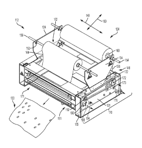
Turning now to FIGS. 4-13, an exemplary converter 112 for expanding pre-slit
sheet stock materials will be further described in the following paragraphs.
The
converter 112, cooperates with a supply 124 of expandable slit sheet stock
material
126 to produce a resultant expanded slit sheet packaging material, i.e., an
expanded
dunnage product 130.
The converter 112 generally includes a housing, which includes a frame 132.
.. The illustrated frame 132 includes opposing, laterally-spaced side panels
131
coupled to one or more base panels 133 for resting on a work surface, such as
a
table. Coupled to the frame 132, such as to the side panels 131, are one or
more
means for supporting sheet material, such as one or more supply supports 134.
In
the illustrated converter 112, a pair of opposing laterally-spaced supply
supports 134
are respectively coupled to the pair of side panels 131. The supply supports
134 are
11
CA 03057823 2019-09-24
WO 2018/175742 PCT/US2018/023799
spaced apart in a lateral direction 140. The lateral direction 140 extends
transverse a
longitudinal direction 150 extending from a rear 149 of the frame 132 to a
front 151 of
the frame 132 having an outlet for dispensing of expanded dunnage. The
longitudinal
direction 150 is parallel the feed direction of the sheet stock material
through the
converter 112.
A pair of axles 154 and 156 are supported by the supply supports 134, such
as in notches 152 of the supply supports 134 as shown. The rearmost axle 154
is
positioned for supporting the supply 124 of expandable sheet stock material
126, and
may receive and support a core 160 of a roll of sheet material in the
expandable
supply 124. The forwardmost axle 156 is positioned for supporting a supply 162
of
separator material 164, which may include an interleaf paper. The separator
material
164 may be a tissue paper, thin kraft paper such as thinner than the
expandable
sheet stock material, plastic, a combination thereof, etc. Like the supply 124
of
expandable sheet stock material 126, the separator supply 162 may be provided
as a
roll, such as wound about a hollow core that may be received on the axle 156.
Additionally or alternatively, the separator supply 162 may be provided in a
fan-folded
stack, and an associated supply support may include a shelf for supporting the
stack.
Referring in particular to FIGS. 6 and 7, the converter 112 also provides a
means for gripping the expandable sheet stock material 126 as it is drawn from
the
supply 124 includes an expansion assembly 170. The expansion assembly 170 is
spaced downstream of the one or more supply supports 134. The downstream
direction is equivalent to the feed direction, and follows the path of the
expandable
sheet stock material 126 from the supply 124 to an outlet 171 of the dunnage
conversion machine 112.
The illustrated expansion assembly 170 includes a pair of tensioning members
172 and 173 that receive and grip the unexpanded sheet stock material 126
drawn
from the supply 124. The expandable sheet stock material 126 extends between
the
pair of tensioning members 172 and 173. The tensioning members 172 and 173 are
positioned downstream of the rearmost axle 154 and are rotatably coupled to
the
side panels 131 of the frame 132 for rotation about respective axes of
rotation 176.
12
CA 03057823 2019-09-24
WO 2018/175742 PCT/US2018/023799
As depicted, opposed lateral ends 177 of each of the tensioning members 172
and
173 are received in the side panels 131, though other means of support may be
appropriate.
At least one of the tensioning members 172 and 173 may be powered by a
suitable motor 178. The motor 178 drives rotation of a force transfer axle 180
to
which the first driven tensioning member 172 is coupled by a suitable force
transfer
member 182 (FIG. 7), such as a belt or chain, which may be toothed in some
embodiments. In some embodiments, the second tensioning member 173 may be
driven, or both tensioning members 172 and 173 may be driven, such as in the
same
or opposing directions.
Downstream of the supply supports 134 and of the pair of tensioning members
172 and 173, is a pair of expansion members 190 and 192. The pair of expansion
members 190 and 192 are longitudinally-spaced from the pair of tensioning
members
172 and 173. The pair of expansion members 190 and 192 are spaced apart from
one another to enable receipt of the sheet stock material 126 therebetween.
Particularly, the depicted pair of expansion members 190 and 192 are
positioned to
grip the expanded form of the sheet stock material 126, i.e., a continuous
strip of
expanded dunnage. Tension to expand the expandable sheet stock material 126
from an unexpanded form to the expanded form of the continuous strip of
dunnage is
provided between the pair of tensioning members 172 and 173 and the pair of
expansion members 190 and 192.
Turning to specifics of the expansion members 190 and 192, the first
expansion member 190 and the second expansion member 192 are rotatably
coupled to the side panels 131 of the frame 132. The expansion members 190 and
192 are coupled for rotation about parallel respective first and second axes
of
rotation 194 and 196. As depicted, opposed lateral ends 198 of each of the
expansion members 190 and 192 are received in the side panels 131, though
other
means of support may be appropriate.
The second expansion member 192 is an upper expansion member located
above the first expansion member 190. The opposed lateral ends 198 of the
second
13
CA 03057823 2019-09-24
WO 2018/175742 PCT/US2018/023799
expansion member 192 include respective rotating members 200 and 202 coupled
thereto for allowing driving of each of the first and second expansion members
190
and 192. The rotating member 200 is a pulley wheel, such as a toothed pulley
wheel,
for receiving a transfer member 204 (FIG. 6), such as a belt or chain, which
may be
toothed. The transfer member 204 extends between a suitable rotating member
206,
such as a pulley wheel coupled to a lateral end 177 of the first driven
tensioning
member 172. The transfer member 204 enables joint rotation of the first driven
tensioning member 172 and the second expansion member 192, such as in the same
direction, by the motor 178.
On the opposed side of the converter 112, the rotating member 202, such as a
toothed gear, receives a transfer member 210 (FIG. 7), such as another belt or
chain,
which may be toothed. The transfer member 210 is received at each of the
rotating
member 202 and a rotating member 212, such as a toothed gear. The rotating
member 212 is coupled to the respective lateral end 198 of the first expansion
member 190 for allowing joint rotation of the first expansion member 190 with
the
second expansion member 192. A supplemental support rotating member 218, such
as another toothed gear, is further rotationally coupled to the respective
side panel
131 adjacent the gears 202 and 212 for providing support to the transfer
member
210. As depicted, the expansion members 190 and 192 rotate in opposite
directions.
Together, the transfer members 182, 204, and 210 provide rotational
intercoupling of the respective first driven tensioning member 172 and the
expansion
members 190 and 192. Accordingly, the motor 178 is configured to drive the
first
tensioning member 172 and each of the first expansion member 190 and the
second
expansion member 192.
In other embodiments, an alternative construction may enable any of: (i)
rotation of the second expansion member 192 in an opposite rotational
direction
relative to the first tensioning member 172, (ii) rotation of the first and
second
expansion members 190 and 192 in the same direction, or (iii) alternative or
additional driving of the first expansion member 190 by the motor 178. In even
other
embodiments, neither of the first and second expansion members 190 and 192 may
14
CA 03057823 2019-09-24
WO 2018/175742 PCT/US2018/023799
be driven, and tension at the outlet 171 of the converter 112 may be provided
manually, such as by a user. In still other embodiments, the tensioning
members 172
and 173 may be omitted altogether, and tension to expand the sheet stock
material
126 may be provided between the supply 124 and one of the pair of expansion
members 190 and 192, an externally applied force, or a manually applied force.
The tensioning members 172 and 173 and/or the expansion members 190
and 192 may include features that assist in maintaining the ability to apply
tension to
and feed the sheet stock material, expanded or unexpanded. As shown in FIG. 8,
to
maintain grip on the expanded form of the sheet stock material being expanded
between the tensioning members 172 and 173 and the expansion members 190 and
192, the illustrated expansion members 190 and 192 include a plurality of
gripping
members 220. The gripping members 220 are configured to maintain tension on
the
expanded form of the sheet stock material, also referred to as the continuous
strip of
expanded dunnage (not shown), such that tearing, crushing, and/or jamming of
the
strip of expanded dunnage is prevented or minimalized. The gripping members
220,
such as teeth, of each of the respective expansion members 190 and 192 are
laterally-spaced apart from one another. The depicted gripping members 220
expend
fully circumferentially about the expansion members 190 and 192 and are
equally
laterally spaced apart from one another. The depicted gripping members 220 of
the
first expansion member 190 are laterally aligned at the same respective
lateral
positions between the opposed lateral ends 198 as the gripping members 220 of
the
second expansion member 192. Alternative spacings, arrangements, shapes,
and/or
sizes of gripping members may be suitable in other embodiments.
Referring now to FIGS. 9-11, spacing between the rotational axes 194 and
196 of the expansion members 190 and 192 is controlled to prevent or
minimalize
this tearing, crushing, and/or jamming via support members 230 of the
expansion
assembly 170 and by an adjustment means, such as one or more adjustment
members 240 of the expansion assembly 170. The spacing may be adjusted to
accommodate strips of expanded dunnage having differing volumetric dimensions,
CA 03057823 2019-09-24
WO 2018/175742 PCT/US2018/023799
such as where differing unexpanded sheet materials have different thicknesses
and/or different slit arrangements.
A set of opposed, laterally-spaced support members 230 are pivotably coupled
to the respective side panels 131 of the frame 132. The support members 230
support the lateral end portions 198 of the first expansion member 190 such
that
pivoting movement of the support members 230 changes a position of the first
axis of
rotation 194 of the first expansion member 190 relative to the second axis of
rotation
196 of the second expansion member 192. For example, the lateral end portions
198
of the first expansion member 190 are received through the support members
230. A
fastener 242 couples one longitudinal end 244 of each support member 230 to
the
respective side panel 131. The support members 230 pivot about the fasteners
242
and about a pivoting axis 246 extending through the fasteners 242.
The adjustment means is selectively positionable to cause movement of the
support members 230, and thereby to change the position of the first axis of
rotation
194 relative to the second axis of rotation 196. Moreover, the adjustment
means is
adjustable such that the parallel relationship between the first and second
axes of
rotation 194 and 196 is maintained at each of a plurality of positions of the
adjustment means.
In alternative embodiments, the support members 230 may be integral with
one another, such as being connected via a support extending laterally between
the
support members 230. Additionally or alternatively, a single adjustment member
240
may provide for pivoting adjustment of the support member(s), where the single
adjustment member 240 may extend laterally between the support member(s).
As illustrated, opposed longitudinal ends 250 of at least one of the support
members 230 are supported by an adjustable adjustment means. As illustrated,
the
opposed longitudinal ends 250 of each of the support members 230 are supported
by
a respective adjustment member 240. The adjustment member 240 is received in
an
adjustment orifice 252 of the respective support member 230. The illustrated
lateral
end portions 198 of the first expansion member 190 are disposed longitudinally
between the fasteners 242 and the adjustment members 240. In some embodiments,
16
CA 03057823 2019-09-24
WO 2018/175742
PCT/US2018/023799
the adjustment members 240 may be longitudinally disposed between the lateral
end
portions 198 of the first expansion member 190 and fasteners 242.
Referring now to one of the adjustment members 240, but equally applicable
to each of the adjustment members 240, the adjustment member 240 is coupled,
such as rotatably coupled, to the frame 132, such as to the respective side
panel
131. The adjustment member 240 is selectively adjustable, such as manually,
between any of a plurality of positions effecting pivoting of the support
member 230.
The positions are each predetermined and tactilely-detectable in view of the
adjustment member 240 having a plurality of sections of differing thickness.
The adjustment member 240 is coupled to the respective pivoting support
member 230 such that selective positioning in any of the plurality of
positions of the
adjustment member 240 causes the sections of differing thickness to be
interchangeably positionable relative to the first axis of rotation 194. The
interchangeable positioning adjusts the position of the respective pivoting
support
member 230 in any of a plurality of positions of the respective pivoting
support
member 230. The interchanging of the sections of differing thickness thereby
causes
changing of the position of the first axis of rotation 194 relative to the
second axis of
rotation 196.
Particularly, the sections of differing thickness are circumferentially spaced
apart, such as equally spaced apart, about a circumference of the adjustment
member 240. The adjustment member 240 is rotatable about an adjustment axis
262
relative to the frame 132 to change the positioning of the sections of
differing
thickness relative to the frame 132. This is accomplished by creating an
eccentric --
offsetting the adjustment axis 262 about which the adjustment member 240
rotates
from a centerline of the adjustment member 240.
As depicted, a pair of opposing sections of differing thickness 259 and 260,
one being thicker than the other, are defined by a spacing between the
adjustment
axis 262 and a radially outer point 264 of each of the sections of differing
thickness
259 and 260. The sections 259 and 260 each have a different thickness in view
of
the adjustment member 240 being an eccentric where the adjustment axis 262 is
17
CA 03057823 2019-09-24
WO 2018/175742 PCT/US2018/023799
offset from a central longitudinal axis of the adjustment member 240. The
thickness
dimension of each of the sections of differing thickness 259 and 260 extends
along a
plane 266 (FIG. 11) that is disposed orthogonal to the first axis of rotation
194. In
other embodiments, the adjustment member 240 may include any suitable number
of
.. sections of differing thickness 259 and 260 and/or the sections of
differing thickness
259 and 260 may be otherwise spaced from one another about the adjustment
member 240.
Eccentric rotation of the adjustment member 240 about the adjustment axis
262 causes the positionable sections of differing thickness 259 and 260 to be
interchangeably positionable between an orientation with an upwardly-facing
thicker
portion 259 (FIG. 11) and an orientation with an upwardly-facing thinner
portion 260
(FIG. 13). Only one section 259, 260 of differing thickness at a time can
occupy an
upwardly-facing acting position. At least a portion of the support member 230
is
disposed between an upwardly-facing portion and the first axis of rotation 194
to
cause lifting or lowering pivoting movement of the support member 230. To
allow for
the interchangeable positioning, the adjustment orifice 252 is configured,
such as
having an elliptical or oblong shape to accommodate the eccentric rotation of
the
adjustment member 240 about the offset adjustment axis of rotation 262.
For example, looking first to FIGS. 10 and 11, the adjustment member 240 is
provided in a default position. The thicker section 259, shown best in the
cross-
section of FIG. 11, is positioned in the upwardly-facing acting position. The
adjustment member 240 may be rotated such that the opposing less-thick
(thinner)
section 260 may be interchangeably rotated into the upwardly-facing acting
position,
as shown in FIGS. 12 and 13, while the thicker section 259 is rotated into a
lower
non-acting position, or downwardly-facing non-acting position, opposite the
upwardly-
facing acting position. In particular, each of the opposing adjustment members
240 is
identically adjusted to maintain for uniform gripping across an expanded sheet
stock
material extending between the first and second expansion members 190 and 192.
In
this secondary position of the adjustment members 240, the respective support
members 230 are downwardly pivoted towards the base panel 230. The secondary
18
CA 03057823 2019-09-24
WO 2018/175742 PCT/US2018/023799
position of the adjustment members 240 shown in FIGS. 12 and 13 provides for
an
increased spacing between the first and second axes of rotation 194 and 196 of
the
first and second expansion members 190 and 192 than is provided by the default
position of the adjustment members 240 shown in FIGS. 9-11.
Turning again briefly to FIG. 11, the adjustment member 240 is maintained in
each of the default and secondary positions by a biasing means. The biasing
means,
such as opposed spring plungers 280, prevent rotation of the adjustment member
240. The spring plungers 280 are generally disposed between the pivoting
support
members 230 and the respective adjustment members 240.
More particularly, a spring plunger 280 is coupled to each of the support
members 230 for engaging with the respective adjustment members 240. Each
spring plunger 280 includes a plunger 282 received into the respective support
member 230 and into a plunger orifice 284 extending between the pair of
sections of
differing thickness 260 of the respective adjustment member 240. A biasing
member
286, such as a coil spring, maintains the plunger 282 into engagement in the
plunger
orifice 284. The plunger orifice 284 may be configured, such as having tapered
portions, such that the plunger 282 is automatically eased out of one side of
the
plunger orifice 284 located at one of the sections of differing thickness 260
and into
engagement into the opposite side of the plunger orifice 284 located at the
other of
the pair of sections of differing thickness. In some embodiments, the plunger
orifice
284 may not extend fully through the adjustment member 240, and thus opposed
plunger orifices may be provided to provide similar function. In some
embodiments
including only a single adjustment member 240, one or two spring plungers 280
may
be used.
Turning now to FIGS. 14-17, another embodiment of an exemplary dunnage
conversion machine is illustrated at 312. The exemplary dunnage conversion
machine 312 is substantially the same as the above-referenced dunnage
conversion
machine 112, and consequently the same reference numerals but indexed by 200
are used to denote structures corresponding to similar structures in the
dunnage
conversion machine 312. In addition, the foregoing description of the dunnage
19
CA 03057823 2019-09-24
WO 2018/175742 PCT/US2018/023799
conversion machine 112 is equally applicable to the dunnage conversion machine
312 except as noted below, and particularly with respect to the adjustment
means of
the dunnage conversion machine 312. Moreover, it will be appreciated upon
reading
and understanding the specification that aspects of the dunnage conversion
machines 112 and 312 may be substituted for one another or used in conjunction
with one another where applicable.
Turning first to FIGS. 14-16, the dunnage conversion machine 312, also
referred to as a converter 312, is provided for manual expansion of an
expandable
sheet stock material 326 of an expandable supply 324. The converter 312
generally
includes a housing, which includes a frame 332. The illustrated frame 332
includes
opposing, laterally-spaced side panels 331 coupled between laterally-extending
support portions 333. The side panels 331 are supply supports and provide
means
for supporting sheet material. As illustrated, a lateral direction 340 extends
transverse
a longitudinal direction 350 extending from a rear of the frame 332 to a front
of the
frame 332 having an outlet for dispensing of expanded dunnage. The
longitudinal
direction 350 is parallel the feed direction of the sheet stock material
through the
converter 312.
A pair of axles 354 and 356 are supported by the side panel/supply supports
331, such as in notches 352 as shown. The rearmost axle 354 is positioned for
supporting the supply 324 of expandable sheet stock material 326, such as
receiving
a core 360 of a roll of sheet material of the expandable supply 324. The
foRivardmost
axle 356 is positioned for supporting a supply 362 of separator material 364.
A means for gripping the expandable sheet stock material 326 as it is drawn
from the supply 324 includes an expansion assembly 370. The expansion assembly
370 is spaced downstream of the rearmost axle 354. The downstream direction is
parallel the longitudinal direction 350 and follows the path of the expandable
sheet
stock material 326 from the supply 324 to an outlet 371 of the dunnage
conversion
machine 312. Laterally-opposed end portions of the expansion assembly 370 may
be
at least partially contained within an assembly housing 372 coupled to the
frame 332.
CA 03057823 2019-09-24
WO 2018/175742 PCT/US2018/023799
The illustrated expansion assembly 370 includes a pair of expansion members
390 and 392 downstream of the rearmost axle 354. The pair of expansion members
390 and 392 are spaced adjacent one another, such as in engagement with one
another, to enable gripping of the unexpanded sheet stock material 326
therebetween. Particularly, the depicted pair of expansion members 390 and 392
are
positioned to grip the expanded form of the sheet stock material 326, i.e., a
continuous strip of expanded dunnage. Tension to expand the expandable sheet
stock material 326 from an unexpanded form to the expanded form of a
continuous
strip of dunnage at the outlet 371 is provided between the pair of expansion
members 390 and 392 and an externally applied force provided adjacent the
outlet
371, such as a manually applied force.
Turning to specifics of the expansion members 390 and 392, the first
expansion member 390 and the second expansion member 392 are rotatably
coupled to the side panels 331 of the frame 332 for rotation about parallel
respective
first and second axes of rotation 394 and 396. As depicted, opposed lateral
ends 398
of each of the expansion members 390 and 392 are received in the side panels
331,
though other means of support may be appropriate. The second expansion member
392 is a lower expansion member located below the first expansion member 390.
The expansion members 390 and 392 may include features that assist in
maintaining the ability to apply tension to and feed the sheet stock material,
expanded or unexpanded. For example, the depicted expansion members 390 and
392 each include a plurality of gripping members 420. The gripping members
420,
such as teeth, of each of the respective expansion members 390 and 392 are
laterally-spaced apart from one another. The depicted gripping members 420
expend
fully circumferentially about the expansion members 390 and 392 and are
equally
laterally spaced apart from one another. The depicted gripping members 420 of
the
first expansion member 390 are laterally aligned at the same respective
lateral
positions between the opposed lateral ends 398 as the gripping members 420 of
the
second expansion member 392. Alternative spacings, arrangements, shapes,
and/or
sizes of gripping members may be suitable in other embodiments.
21
CA 03057823 2019-09-24
WO 2018/175742 PCT/US2018/023799
Turning now to FIG. 17, spacing between the rotational axes 394 and 396 of
the expansion members 390 and 392 is controlled to optimize a uniform gripping
tension applied across a lateral length of the sheet stock material 326 drawn
between
the expansion members 390 and 392. The spacing may be adjusted to
accommodate sheet material having differing different thicknesses and/or
different slit
arrangements. Adjustment of the spacing is jointly controlled by pivotably-
mounted
support members 430 of the expansion assembly 370 and by an adjustment means.
For example, the expansion assembly 370 includes one or more adjustment
members 440.
A set of opposed, laterally-spaced support members 430 are pivotably coupled
to the respective side panels 331 of the frame 332. The pivotable support
members
430 support the lateral end portions 398 of the first expansion member 390
such that
pivoting movement of the pivotable support members 430 changes a position of
the
first axis of rotation 394 of the first expansion member 390 relative to the
second axis
of rotation 396 of the second expansion member 392. For example, the lateral
end
portions 398 of the first expansion member 390 are received through support
openings in the pivotable support members 430. A fastener 442 couples one
longitudinal end 444 of each support member 430 to the respective side panel
331.
The pivotable support members 430 are configured to pivot about the fasteners
442
and about a pivoting axis 446 extending through the fasteners 442.
The adjustment means is selectively positionable to cause movement of the
support members 430 about the pivoting axis 446, and thereby to change the
position of the first axis of rotation 394 relative to the second axis of
rotation 396.
Moreover, the adjustment means is adjustable such that the parallel
relationship
between the first and second axes of rotation 394 and 396 is maintained at
each of a
plurality of positions of the adjustment means.
In alternative embodiments, the pivotable support members 430 may be
integral with one another, such as being connected via a support extending
laterally
between the support members 430. Additionally or alternatively, a single
adjustment
.. member 440 may provide for pivoting adjustment of the pivotable support
member(s),
22
CA 03057823 2019-09-24
WO 2018/175742 PCT/US2018/023799
where the single adjustment member 440 may extend laterally between the
pivotable
support member(s). To simplify the description, only one of the adjustment
members
440 will be described, with the understanding that an equivalent adjustment
member
440 is provided on an opposite end of the expansion members 390 and 392.
As illustrated, a longitudinal end 450 of at least one of the pivotable
support
members 430 is moved by an adjustable adjustment means. As illustrated, the
longitudinal end 450 of each of the pivotable support members 430 is disposed
opposite the respective supported end 444 of the respective pivotable support
member 430. The longitudinal ends 450 of each of the pivotable support members
430 are moved by a respective adjustment member 440. The respective adjustment
members 440 typically are disposed against the respective pivotable support
members 430.
The adjustment member 440 is coupled, such as linearly translatably coupled,
to the frame 332, such as to the respective side panel 331. Particularly, the
adjustment member 440 includes an adjustment orifice 452. A fastener 454, such
as
a threaded bolt, is received through the adjustment orifice 452 and holds the
adjustment member 440 to the respective pivotable support member 430.
A support pin 455 (a bolt threaded into the block), also is received through
the
adjustment orifice 452 and is coupled to the respective side panel 331. A
biasing
member 456, such as a coil spring is disposed between a head 457 of the
support
pin 455 and the adjustment member 440. A flat washer 458 also may be disposed
between the biasing member 456 and the adjustment member 440 to provide
uniform
application of force of the biasing member 456 to the adjustment member 440.
The pivotable support member 430 further may include a support orifice 459
extending therethrough for receiving the support pin 455. The support orifice
459
may have an oblong or elliptical shape for allowing pivoting of the pivotable
support
member 430 relative to the support pin 455. The coupling of the support member
430
on the support pin 455 enables guidance of the pivotable support member 430
during
pivoting. In other embodiments, however, it may be suitable for the pivotable
support
member 430 not to capture the support pin 455.
23
CA 03057823 2019-09-24
WO 2018/175742 PCT/US2018/023799
The adjustment member 440 is selectively adjustable relative to the frame 332
and relative to the first axis of rotation 394 between any of a plurality of
positions
effecting pivoting of the pivotable support member 430. Movement of the
adjustment
member 440 is transferred into pivoting movement of the pivotable support
member
430 by continued engagement of the adjustment member 440 with the pivotable
support member 430, in coordination with a biasing force of the biasing member
456
applied to the adjustment member 440.
To allow for the adjustment, the adjustment member 440 includes a pair of
opposing sections of differing thickness 459 and 460, one being thicker than
the
other. The sections 459 and 460 are defined by a spacing between an adjustment
surface 462 of the adjustment member 440 and the pivotable support member 430.
The thickness dimension of each of the sections of differing thickness 459 and
460
extends along a plane 466 that is disposed orthogonal to the first axis of
rotation 394.
As illustrated, the section 459 has a greater thickness dimension than the
section
460. In other embodiments, the adjustment member 440 may include any suitable
number of sections of differing thickness.
The sections of differing thickness 459 and 460 are linearly spaced apart, and
longitudinally separated from one another, along the adjustment surface 462 of
the
adjustment member 440. A ramp portion 464 provides a change in height between
the pair of sections 459 and 460. In other embodiments, the sections of
differing
thickness may be linearly spaced from one another along the adjustment surface
462
with any suitable spacing therebetween.
The adjustment member 440 is linearly translatable relative to the frame 332
to change the positioning of the sections of differing thickness 459 and 460
relative to
the frame 332. Linear translation of the adjustment member 440 along the
support
member 430 causes the sections 459 and 460 each to be positionable between an
acting position 470 and an adjacent non-acting position 471. Only one section
of
differing thickness 459 or 460 at a time can occupy the acting position 470.
The translation is effected by a user pulling or pushing on a handle portion
480
of the adjustment member 440 that extends through an opening 482 in the
assembly
24
CA 03057823 2019-09-24
WO 2018/175742 PCT/US2018/023799
housing 372. The ramp portion 464 allows for efficient linear translation of
the
adjustment member 440 as the flat washer 458 is engaged with the adjustment
surface 462. After translation, the adjustment member 440 is maintained in
position
by the biasing force of the biasing member 456.
The plurality of adjustment positions of the adjustment member 440 are each
predetermined and tactilely-detectable in view of the adjustment member 440
having
a plurality of sections of differing thickness 459 and 460. The adjustment
member
440 is engaged with the respective pivotable support member 430 such that
selective
positioning in any of the plurality of positions of the adjustment member 440
causes
the sections 459 and 460 to be positionable relative to the first axis of
rotation 394.
As illustrated, at least a portion of the pivotable support member 430 is
disposed
between the acting position 470 and the first axis of rotation 394 to cause
lifting or
lowering pivoting movement of the support member 430.
The movement of the adjustment member 440 adjusts the respective pivotable
support member 430 in any of a respective plurality of positions. The movement
of
the sections of differing thickness 459 and 460 thereby changes the position
of the
first axis of rotation 394 relative to the second axis of rotation 396 to vary
the spacing
therebetween.
In summary, a dunnage conversion machine 12, 112, 312 according to any of
the FIGS. 1 and 4-17, for converting an expandable pre-slit sheet stock
material into
a relatively less dense dunnage product, includes an improved expansion
assembly
20, 170, 370 that provides means for adjusting the spacing between axes of
rotation
194, 196, 394, 396 of components 190, 192, 390, 392 through which the sheet
stock
material 26, 126, 326 is drawn. The adjustability enables pre-slit sheet stock
materials of differing thicknesses and/or having differing slit patterns to be
fed
through the expansion assembly 20, 170, 370 with no or minimal compression of
an
expanded dunnage product, jamming in the conversion machine, bunching, and/or
tearing of the pre-slit sheet stock material or expanded dunnage product 24,
130
resulting from expansion of the pre-slit sheet stock material 26, 126, 326.
CA 03057823 2019-09-24
WO 2018/175742 PCT/US2018/023799
Additionally, any of the aforementioned converters 12, 112, or 312 may
include an optional separating means, such as a separator. With respect to the
converter 12, but applicable to either of the converter 112 or 312, an
optional
separating means 22 (FIG. 1) may include a separate or sever distinct dunnage
products 24 from the continuous strip of dunnage 26. An optional separator of
the
separating means 22 may include one or more cutting members, which may be
actuated manually or automatically. An exemplary severing assembly is
described in
U.S. Patent No. 4,699,609 to Ranpak Corp. of Concord Township, Ohio.
In some situations, the separating means 22 may be omitted altogether, such as
when discrete lengths of sheet material are supplied to the converter 12.
Another
alternative is to employ a sheet stock material that is perforated across its
width so
that a length of dunnage product can be torn from the dunnage strip 26. The
perforations can be formed in the stock material before being supplied to the
converter 12 or formed as part of the conversion process. Additionally or
alternatively, the converter 12 may be configured to automatically separate a
desired
length of dunnage product from dunnage strip made of perforated stock
material.
This can be accomplished by providing an additional set of rotating members
upstream or downstream of the downstream-most set of rotating members of the
expansion assembly 20, and stopping whichever set is upstream, while
continuing to
feed sheet material through the other set of rotating members.
The present invention also provides a method of converting an expandable
sheet stock material 26, 126, 326 into a relatively less dense dunnage product
24,
130. The method includes the step of (a) drawing a first sheet stock material
having a
first slit pattern from a supply 124, 324 between a pair of rotating members
190, 192,
390, 392 under tension to cause the first sheet stock material to expand in at
least
one dimension. The method also includes the steps of (b) replacing the first
sheet
stock material with a second sheet stock material having a second slit
pattern, (c)
adjusting a spacing between axes of rotation 194, 196, 394, 396 of the
rotating
members 190, 192, 390, 392, and (d) drawing the second sheet stock material
between the pair of rotating members 190, 192, 390, 392 under tension to cause
the
26
CA 03057823 2019-09-24
WO 2018/175742 PCT/US2018/023799
second sheet stock material to expand in at least one dimension. The adjusting
step
may include providing tactilely-detectable positions representing at least two
different
amounts of spacing between the axes of rotation 194, 196, 394, 396 of the
rotating
members 190, 192, 390, 392. The adjusting step may include eccentric rotation
to
effect adjusting between the positions.
Although the invention has been shown and described with respect to a
certain illustrated embodiment or embodiments, equivalent alterations and
modifications will occur to others skilled in the art upon reading and
understanding
the specification and the annexed drawings. In particular regard to the
various
functions performed by the above described integers (components, assemblies,
devices, compositions, etc.), the terms (including a reference to a "means")
used to
describe such integers are intended to correspond, unless otherwise indicated,
to
any integer which performs the specified function (i.e., that is functionally
equivalent),
even though not structurally equivalent to the disclosed structure which
performs the
.. function in the herein illustrated embodiment or embodiments of the
invention. The
term "coupling" may refer to direct coupling of one integer to another or to
indirect
coupling of integers, such as with one or more integers therebetween. The term
"and/or," such as used in "a and/or b" is defined as including either or both
of (i) a and
b and (ii) a or b.
27