Note: Descriptions are shown in the official language in which they were submitted.
TITLE
[0001] Chair Having Tilting Seat And Back
FIELD
[0002] There is described a chair with a seat and back that tilt to provide
ergonomic seat
positions.
BACKGROUND
[0003] United States Patent 8,272,692 (Epperson) entitled "Office Chair
Having Tiltable
Seat And Back", describes a chair with a seat and back that tilt to provide
ergonomic seat
positions. There will now be described a chair that is an alternative to
Epperson and is
believed to provide advantages over Epperson.
SUMMARY
[0004] There is provided a chair which includes a support body having a
seat support
portion and a back support portion. A seat track is positioned on the seat
support portion. A
first seat portion engages the seat track on the seat support portion for
forward and rearward
movement along the seat track between a forward position and a rearward
position. A second
seat portion is provided having an upwardly extending back rest. At least one
back rest track
is provided on one of the back support portion or the back rest. At least one
track follower is
provide on another of the back support portion or the back rest. The second
seat portion is
pivotally connected to the first seat portion. Movement of the first seat
portion forward along
the seat track toward the forward position draws the second seat portion
forward with forward
movement of the second seat portion causing movement of the back rest
downwardly with
such movement accommodated by cooperation of the at least one back rest track
and the at
least one track follower.
[0005] The chair, as described above, allows for subtle forward and
backward movement.
This movement activates the major muscle groups in the legs without being
distracting or
interfering with work activities.
[0006] Although beneficial results may be obtained through the use of
the chair, as
described above, it has been found that more beneficial results may be
obtained when the first
seat portion is biased into the rearward position. With biasing, after the
user has consciously
CA 3057933 2019-10-08
2
exerted a force to move the first seat portion forward, the first seat portion
is drawn slowly
back to the starting position as the force is released.
[0007] Although beneficial results may be obtained through the use of
the chair, as
described above, it has been determined that a seat track which is arcuate and
symmetrical
works the best. When the first seat portion moves forward, the second seat
portion is drawn
forwardly and upwardly. This serves a number of purposes. It serves to bias
the first seat
portion and the second seat portion to the rearward position, it accentuates
the movement and
it helps the user avoid sliding forward.
[0008] In order to improve aesthetic appearance, it is preferred that
the first seat portion
and the second seat portion share an overlying fabric covering. In order to
improve comfort
and help the user avoid sliding forward, all or a portion of the overlying
fabric covering the
second seat portion may be provided with a friction inducing and pressure
relieving profile.
BRIEF DESCRIPTION OF THE DRAWINGS
[0009] These and other features will become more apparent from the
following description
in which reference is made to the appended drawings, the drawings are for the
purpose of
illustration only and are not intended to be in any way limiting, wherein:
[0010] FIG. 1 is a side elevation view of a chair having tilting seat
and back in a rearward
position.
[0011] FIG. 2 is a side elevation view of the chair of FIG. 1 in a
forward position.
[0012] FIG. 3 is a detailed side elevation view of the seat track when
the chair is in a
rearward position, as shown in FIG. 1.
[0013] FIG. 4 is a detailed side elevation view of the seat track when
the chair is in a
forward position, as shown in FIG. 2.
[0014] FIG. 5 is a detailed side elevation view of the back rest track
when the chair is in a
rearward position, as shown in FIG. 1.
[0015] FIG. 6 is a detailed side elevation view of the back rest track when
the chair is in a
forward position, as shown in FIG. 2.
CA 3057933 2019-10-08
3
[0016] FIG. 7 is a top plan view of the chair of FIG. 1.
DETAILED DESCRIPTION
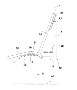
[0017] A
chair, generally identified by reference numeral 10, will now be described
with
reference to FIG. 1 through FIG. 7.
Structure and Relationship of Parts:
[0018]
Referring to FIG. 1 and FIG. 2, chair 10 consists of a support body 12 having
a seat
support portion 14 and a back support portion 16. A seat track 18 is
positioned on seat support
portion 14. A first seat portion 20 engages seat track 18 on seat support
portion 14 for forward
and rearward movement along arcuate seat track 18 between a forward position,
as shown in
FIG. 2 and a rearward position, as shown in FIG. 1. Movement of first seat
portion 20 along
seat track 18 is facilitated by ball bearings 22. It will be apparent that
movement could be
accommodated without the use of ball bearings or with other types of
engagement. It is
preferred that seat track 18 defines a symmetrical arcuate path. FIG. 3
illustrates first seat
portion 20 in a rearward portion on seat track 18. FIG. 4 illustrates first
seat portion 20 on a
forward position on seat track 18.
[0019]
Referring to FIG. 1 and FIG. 2, a second seat portion 24 is provided having an
upwardly extending back rest 26. Referring to FIG. 7, first seat portion 20
and second seat
portion 24 share an overlying fabric covering 28. That portion of overlying
fabric covering 28
that covers second seat portion 24, preferably has a friction inducing and
pressure relieving
profile in the form of openings 30.
[0020] Two back rest
tracks 32 are provided, one on each side of back rest 26. A pair of
track followers 34 are provided on back support portion 16. Track followers 34
move along
back rest tracks 32 during relative movement of back rest 26 and back support
portion 16. It
will be appreciated that this could be reversed with track followers 34
positioned on back rest
26 and back rest tracks 32 on back support portion 16.
[0021]
Referring to FIG. 1 and FIG. 2, second seat portion 24 is pivotally connected
by a
CA 3057933 2019-10-08
4
hinge connection 36 to first seat portion 20. In view of hinge connection 36,
when pressure is
exerted to move first seat portion 20 forward along seat track 18 toward the
forward position,
second seat portion 24 is drawn forward with forward movement of first seat
portion 20.
Referring to FIG. 5, back rest 26 is shown in the rearward position. Referring
to FIG. 6, as
second seat portion 24 drawn forward, back rest 26 is drawn downwardly with
such movement
being accommodated by back rest tracks 32 and track followers 34.
[0022]
Referring to FIG. 1 and FIG. 2, first seat portion 20 is biased by a spring 38
to the
rearward position. First seat portion 20 will always return to the rearward
position when
pressure is removed. It will be apparent that biasing can be accomplished by
other means, such
as a slope to induce a gravity return or a bungee cord.
[0023]
Referring to FIG. 1 and FIG. 2, support body 12 is illustrated has having a
flat base
40 and a single vertical support column 42. It will be appreciated that base
40 may be of
various shapes, such as a spider or multi-legged shape and may also have
casters at the ends
for rolling chair 10.
Operation:
[0024]
Referring to FIG. 1, a user sits centered with his or her tailbone positioned
on
second seat portion 24 with the user's back flush against back rest 26, in the
default rearward
position of chair 10. As the user exerts a forward and downward pressure
through their thighs
onto first seat portion 20, first seat portion 20 slides forward and downward
along the arcuate
seat track 18. As first seat portion 20 slides forward, second seat portion 24
is drawn forward
and slightly upward arcuate seat track 18 because hinge connection 36 ties
movement of second
seat portion 24 to movement of first seat portion 20.
[0025] With
the forward movement of second seat portion 24, an upper portion of back
rest 26 is drawn downwards with movement of back rest 26 being accommodated by
back rest
tracks 32 and track followers 34. Referring to FIG. 2, this results in first
seat portion 20 being
in a forward and downward sloping position and back rest 26 being in a
reclined position.
As the user lessens or removes the forward and downward pressure exerted on
first seat portion
CA 3057933 2019-10-08
5
20, spring 38 pulls first seat portion 20 rearwards and upwards along arcuate
seat track 18. As
first seat portion 20 moves rearward on arcuate seat track 18, second seat
portion 24 is pushed
rearward by the movement of first seat portion 20. As the second seat portion
24 moves
rearward, movement of back rest 26 is accommodated by back rest tracks 32 and
track
followers 34. This returns chair 10 to the default rearward position of FIG.
I.
Advantages:
[0026] 1. The movement of the above described chair is subtle and can
be effected without
interfering with the work activities of a person seated behind a desk.
[0027] 2. The movement activates the major muscle groups in the legs and,
as such, plays
a role in maintaining fitness and burning calories.
[0028] 3. With their tailbone positioned on second seat portion 26,
users do not slide off
the seat as they tilt the seat forward and move into a reclined position. In
contrast, when a
unitary seat is inclined it is difficult to avoid sliding forward.
[0029] 4. The slight upward tilt of the second seat portion 26, combined
with the
downward tilt of first seat portion 24, opens up the hip-thigh angle, which
helps to restore the
natural lordosis (inward curve) of the lumbar spine. This results in increased
comfort for the
user and decreased time spent sitting in a slumped (kyphotic) sitting posture,
which has been
shown to be a major source of lower back pain for office workers.
[0030] In this patent document, the word "comprising" is used in its
non-limiting sense to
mean that items following the word are included, but items not specifically
mentioned are not
excluded. A reference to an element by the indefinite article "a" does not
exclude the
possibility that more than one of the element is present, unless the context
clearly requires that
there be one and only one of the elements.
[0031] The scope of the claims should not be limited by the illustrated
embodiments set
forth as examples, but should be given the broadest interpretation consistent
with a purposive
construction of the claims in view of the description as a whole.
CA 3057933 2019-10-08