Note: Descriptions are shown in the official language in which they were submitted.
CA 03057946 2019-09-24
WO 2018/182836
PCT/US2018/015061
MEDICAL TOOL POSITIONING DEVICES, SYSTEMS, AND METHODS OF USE
AND MANUFACTURE
CROSS-REFERENCE TO RELATED APPLICATIONS
[0001] This application claims priority to the following provisional
applications, the
disclosures of which are incorporated by reference herein: U.S. Application
No. 62/479,218,
filed March 30, 2017; U.S. Application No. 62/489,900, filed April 25, 2017;
and U.S.
Application No. 62/523,706, filed June 22, 2017.
INCORPORATION BY REFERENCE
[0002] All publications and patent applications mentioned in this
specification are herein
incorporated by reference to the same extent as if each individual publication
or patent
application was specifically and individually indicated to be incorporated by
reference.
BACKGROUND
[0003] A wide variety of intravascular medical devices are known. Improved
systems,
devices, and methods that facilitate better control, positioning, and
usability of medical
devices are needed.
SUMMARY
[0004] One aspect of the disclosure is a handle assembly for positioning a
medical tool
(e.g., an ultrasound probe), where a first displacement system for the medical
tool bypasses
a second displacement system for a steerable shaft.
[0005] One aspect of the disclosure is a handle assembly for
positioning a medical tool
(e.g., an ultrasound probe), where a first displacement system for the medical
tool extends
further proximally than a proximal end of a steerable shaft and optionally
further proximally
than a hemostatic valve within the handle assembly.
[0006] One aspect of the disclosure is a handle assembly for
positioning a medical tool
(e.g., an ultrasound probe), wherein the handle assembly includes a first
actuator movable
relative to a handle body, the first actuator adapted to cause axial movement
of the medical
tool and rotation of the medical tool, the handle assembly including a second
actuator
proximal to the first actuator and movable relative to a handle body, the
second actuator
adapted to steer a steerable shaft.
-1-
CA 03057946 2019-09-24
WO 2018/182836
PCT/US2018/015061
[0007] One aspect of the disclosure is a handle assembly for
positioning a medical tool
(e.g., an ultrasound probe), where a first displacement system for the medical
tool is adapted
to be moved axially within the handle body while a steerable shaft is not
moved axially within
the handle body.
[0008] One aspect of the disclosure is a handle assembly for positioning a
medical tool
(e.g., an ultrasound probe), wherein the handle assembly includes a medical
tool rotation
limiter, optionally an assembly, that prevents rotation of the tool beyond a
certain amount.
The rotation limiter can be a compound rotation limiter assembly. The rotation
limiter can
be adapted to allow for more than 360 degree rotation of the medical tool
within the handle
assembly, and prevent optionally less than 720 degrees of rotation, or
optionally less than
675, and optionally less than 630, optionally less than 585, optionally less
than 540, and
optionally less than 495, and optionally less than 450, optionally less than
405.
[0009] One aspect of the disclosure is a handle assembly for
positioning a medical tool
(e.g., an ultrasound probe), wherein the handle assembly includes a medical
tool rotation
limiter, wherein at least a portion of the ultrasound probe rotation limiter
assembly is
disposed proximal to the proximal end of the steerable shaft and proximal to a
hemostatic
valve disposed in the handle body. The rotation limiter may include a
stationary handle
element and a first rotating element, the stationary handle element and the
first rotating
element positioned and configured to interface with one another to prevent
further rotational
movement of the first rotating element beyond a certain amount of rotation.
The rotation
limiter may also include a second rotating element secured to or part of a
medical tool shaft,
the second rotating element rotatable relative to the first rotating element,
the second
rotating element and the first rotating element disposed relative to one
another and each
configured to interface one another to cause combined rotation of the first
and second
rotating elements upon further rotation of the second rotating element.
[00010] One aspect of the disclosure is an ultrasound probe that has a distal
portion that
includes an ultrasound transducer, the distal portion extending further
distally than a distal
end of a steerable sheath and having a radially outer dimension greater than a
radial
dimension of a lumen of the steerable sheath in which the probe is disposed,
the ultrasound
probe further including a flexible circuit strip, the flexible circuit strip
comprising an
insulating substrate, a plurality of conductive traces disposed on and
extending along the
insulating substrate, a portion of each of the plurality of conductive traces
covered by an
insulation member, and a portion of the plurality of conductive traces not
covered by the
-2-
CA 03057946 2019-09-24
WO 2018/182836
PCT/US2018/015061
insulation member, the portion of the plurality of conductive traces that are
not covered by
the second insulation layer defining a probe contact.
[00011] One aspect of the disclosure is one or more elements that secure,
while allowing
movement therein, an ultrasound probe shaft within a handle assembly.
[00012] One aspect of the disclosure is a hard stop feature integrated into a
handle body,
the hard stop feature limiting rotation of a medical tool.
[00013] One aspect of the disclosure is an integrated handle body, the handle
body
including a plurality of guides, some of which may have walls extending along
the body's
length, while some may be transverse thereto.
[00014] One aspect of the disclosure is an ultrasound probe positioning
system,
comprising: a handle assembly, a steerable sheath; and an ultrasound probe,
the handle
assembly in operable communication with the steerable sheath and the
ultrasound probe, the
handle assembly including a handle body with an outer surface that can be
gripped by a
user, a distal ultrasound probe actuator adapted to be moved relative to the
handle body, and
a proximal steerable sheath actuator proximal to the distal actuator adapted
to be moved
relative to the handle body, the steerable sheath having a distal deflectable
region that is in
operable communication with at least one axially actuatable member, wherein
the proximal
steerable sheath actuator is in operable communication with the axially
actuatable member
such that actuation of the proximal steerable sheath actuator relative to the
handle body
causes deflection of the distal deflectable region, and wherein the distal
actuator is adapted
to be rotated relative to the handle body and also adapted to be moved axially
relative to the
handle body, and wherein the distal actuator is in operable communication with
the
ultrasound probe such that axial movement of the distal actuator relative to
the handle body
causes axial movement of the ultrasound probe relative to the distal end of
the steerable
sheath, and such that rotation of the distal actuator relative to the handle
body causes
rotation of the ultrasound probe relative to the distal end of the steerable
sheath,wherein the
handle assembly comprises an ultrasound probe displacement system that is
attached to the
distal ultrasound probe actuator and to an ultrasound probe shaft and that
creates operable
communication between the distal ultrasound probe actuator and the ultrasound
probe shaft,
and wherein at least part of the ultrasound probe displacement system is
disposed within the
handle body and extends further proximally in the handle body than a proximal
end of the
steerable sheath and is attached to the ultrasound probe shaft at a location
proximal to a
proximal end of the steerable sheath, and wherein the ultrasound probe
displacement system
bypasses the steerable sheath within the handle body such that it is not in
operable
-3-
CA 03057946 2019-09-24
WO 2018/182836
PCT/US2018/015061
communication with the steerable sheath within the handle body so that the
ultrasound
probe shaft can be rotated and axially moved without causing movement of the
steerable
sheath within the handle body. Any of the other relevant features herein may
be included in
this system.
[00015] In some embodiments the part of the ultrasound probe displacement
system that is
attached to the ultrasound probe shaft is attached to the ultrasound probe
shaft proximal to a
hemostatic valve disposed within the handle body.
[00016] In some embodiments at least a portion of the ultrasound probe
displacement
system, within the handle body, extends around and outside of the steerable
sheath, and is
adapted to be moved axially relative to the steerable sheath when the distal
actuator is
moved axially. The ultrasound probe displacement system can include, within
the handle
body, a first portion that extends around and outside of the steerable sheath,
and a second
portion in operable communication with the first portion, the second portion
positioned
radially away from the steerable sheath and extends in a direction parallel to
a longitudinal
axis of the sheath. The first portion can include a first rotatable member
with a lumen
through which the steerable sheath and the ultrasound probe shaft extend, and
wherein the
second portion can include a second rotatable member spaced radially away from
the first
rotating member and in operable communication with the first rotating member.
The
ultrasound probe displacement system can further comprise a third rotatable
member with a
proximal end that is proximal to the proximal end of the steerable sheath, the
third rotatable
member positioned radially inward relative to the second rotatable member, the
third
rotating member having a lumen through which the ultrasound probe shaft
extends and
which is secured directly or indirectly to the ultrasound probe shaft.
[00017] In some embodiments the system further comprises a compound ultrasound
probe
rotation limiter assembly disposed within the handle body that prevents the
ultrasound probe
within the handle body from being rotated beyond a certain amount, optionally
wherein at
least a portion of the ultrasound probe rotation limiter assembly is disposed
proximal to the
proximal end of the steerable shaft and proximal to a hemostatic valve
disposed in the
handle body. The rotation limiter assembly can comprise a stationary handle
element and a
first rotating element, the stationary handle element and the first rotating
element positioned
and configured to interface with one another to prevent further rotational
movement of the
first rotating element beyond a certain amount of rotation. The system can
further comprise
a second rotating element secured to or part of the ultrasound probe shaft,
the second
rotating element rotatable relative to the first rotating element, the second
rotating element
-4-
CA 03057946 2019-09-24
WO 2018/182836
PCT/US2018/015061
and the first rotating element disposed relative to one another and each
configured to
interface one another to cause combined rotation of the first and second
rotating elements
upon further rotation of the second rotating element. The compound ultrasound
probe
rotation limiter assembly can allow for the proximal portion of the ultrasound
probe within
the handle body to be rotated greater than 360 degrees, and prevents rotation
of, optionally,
more than 720 degrees, and optionally, more than 450 degrees.
[00018] In some embodiments the ultrasound probe has a distal portion that
includes an
ultrasound transducer, the distal portion extending further distally than a
distal end of the
steerable sheath and optionally having a radially outer dimension greater than
a radial
dimension of a lumen of the steerable sheath in which the probe is disposed,
the ultrasound
probe further including a flexible circuit strip, the flexible circuit strip
comprising an
insulating substrate, a plurality of conductive traces disposed on and
extending along the
insulating substrate, a portion of each of the plurality of conductive traces
covered by an
insulation member, and a portion of the plurality of conductive traces not
covered by the
insulation member, the portion of the plurality of conductive traces that are
not covered by
the second insulation layer defining a probe contact.
[00019] One aspect of the disclosure is an intravascular ultrasound probe
system,
comprising: a handle comprising a handle body and an actuator, the actuator
movable
relative to the handle body, the handle body comprising a stationary rotation
stop element;
an ultrasound probe comprising a probe shaft at least a part of which is
secured within the
handle body and is in operable communication with the actuator; and first and
second
rotatable members that are rotatable relative to the handle body and to the
stationary rotation
stop element, the first and second rotatable members disposed relative to one
another and
configured to allow the first rotatable member to rotate without moving the
second rotatable
member in a first position and then interface with each other in a second
position and rotate
together when they are interfaced, the second rotatable member and the
stationary rotation
stop element positioned and configured so that further rotation of the second
rotatable
member is prevented when second rotatable member and the stop element
interface one
another, thus preventing the ultrasound probe shaft from being rotated beyond
a certain
amount.
[00020] In some embodiments the compound rotation limiter assembly is
configured to
allow the proximal end of the ultrasound probe shaft to be rotated more than
360 degrees
within the handle body before preventing it from being rotated further, and
optionally
-5-
CA 03057946 2019-09-24
WO 2018/182836
PCT/US2018/015061
preventing rotation more than 720 degrees, and optionally preventing rotation
more than
450 degrees.
[00021] One aspect of the disclosure is a rotation limiter for an
intravascular ultrasound
probe positioning system, comprising: an annular element with an inner surface
defining a
lumen therein, the annular element including a radially inner extension that
extends further
radially inward than a remainder of the inner surface, the radially inner
extension, in a
sectional end view, having a height from .005 inches to .042 inches and
subtending an angle
from 1 degree to 120 degrees, the annular element further including a radially
outer
extension that extends further radially outward than a remainder of an outer
surface of the
annular element, the radially outer extension subtending an angle 1 degree to
60 degrees,
wherein the remainder of the inner surface has a diameter from .319 inches to
.361 inches ,
and wherein the length of the annular element from a proximal end to a distal
end is from
.095 inches to .188 inches.
[00022] In some embodiments the annular element further comprises a second
radially
outer extension, the second radially outer extension at least 45 degrees away
from the
radially outer extension around the annular element, and optionally 180
degrees away from
the radially outer extension.
[00023] In some embodiments the radially inner extension and the radially
outer extension
are rotationally aligned.
[00024] One aspect of the disclosure is a handle body for positioning an
intravascular
ultrasound probe and preventing rotation of the probe beyond a certain amount,
comprising:
a handle body comprising an integral rotation stop (1418) that extends
radially inward
relative to an outer wall of the handle body, the rotation stop having a
length from .0156
inches to .250 inches, and the rotation stop having a height greater than .143
inches but not
greater than .203 inches.
[00025] In some embodiments the rotation stop includes a stop surface disposed
substantially in an axis that includes a midpoint of the handle body, the
midpoint measured
along a width of the handle body.
[00026] In some embodiments the integral rotation stop has a first width in a
proximal
portion and a second width smaller than the first width in a distal portion,
the distal portion
comprising a free end of the integral rotation stop.
[00027] In some embodiments the integral rotation stop is from 45.14 inches to
55.38
inches from a distal end of the handle body.
-6-
CA 03057946 2019-09-24
WO 2018/182836
PCT/US2018/015061
[00028] One aspect of the disclosure is an integrated handle body for
positioning an
intravascular ultrasound probe, comprising: an integrated elongate handle body
with a
length and width measured perpendicular to one another, the handle body having
a proximal
region that includes first, second and third proximal guides with lengths
longer than their
widths, each of the proximal guides including first and second walls extending
along the
length of the handle body, the first proximal guide being disposed in a
central region of the
handle body, the second and third proximal guides on either side of the first
guide, a central
region that includes a plurality central walls extending transverse to the
walls in the
proximal region, the plurality of central walls each including a plurality of
recessed regions
formed therein, and a distal region that includes first, second and third
distal guides with
lengths longer than their widths, each of the distal guides including first
and second walls
extending along the length of the handle body and transverse to the central
walls, the first
distal guide being disposed in a central region of the handle body, the second
and third distal
guides on either side of the first distal guide.
[00029] In some embodiments at least one of the first, second, and third
proximal guides
shares a wall with an adjacent proximal guide.
[00030] In some embodiments at least one of the first, second, and third
distal guides
shares a wall with an adjacent distal guide.
[00031] In some embodiments the proximal region further comprises a region
proximal to
the proximal guides that includes a plurality of rotation walls transverse to
the guide walls,
each of the rotation walls including a recessed region formed therein.
[00032] In some embodiments the second proximal guide is radially aligned with
the
second distal guide, and the third proximal guide is radially aligned with the
third distal
guide.
[00033] One aspect of the disclosure is an ultrasound probe shaft member that
provides at
least one of stabilization and driving, comprising: an elongate tubular
element with a
radially outwardly extending spine extending along at least a the length
thereof, the elongate
tubular element having an inner lumen with an inner diameter from .05 inches
to .250
inches, such as from .080 inches to .125 inches, the spine having a height
from .01 inches to
.2 inches, such as .0157 inches to .125 inches, the spine, in a sectional end
view, subtending
an angle from 1 degree to 180 degrees (optionally to 135 degrees, and
optionally to 90
degrees), wherein the elongate tubular element (1240) has a length from .5
inches to 3.5
inches, such as from .75 inches to 2.5 inches. The shaft member can be coupled
to an
-7-
CA 03057946 2019-09-24
WO 2018/182836
PCT/US2018/015061
ultrasound probe shaft, which fixedly secures an outer surface of the probe
shaft to the inner
lumen of the shaft member.
[00034] One aspect of the disclosure is an ultrasound probe positioning
system,
comprising: a steerable shaft with a first stabilizing feature formed in a
distal end region, the
stabilizing feature including at least one surface; an ultrasound probe, at
least a portion of
which is disposed within the steerable shaft and axially and rotationally
moveable relative to
the shaft, the ultrasound probe including a working end that includes an
ultrasound
transducer and a second stabilizing feature including at least one surface
that is configured
and positioned to interface with the first stabilizing feature on the
steerable shaft to prevent
relative movement between the steerable shaft and ultrasound probe in at least
one direction,
wherein when the ultrasound probe is moved distally relative to the interfaced
position, the
relative movement between the steerable shaft and ultrasound probe in at least
one direction
can occur.
[00035] The disclosure herein also includes methods of assembling or
reassembling any of
the subassemblies or assemblies herein, including any of the subassemblies
within any of
the handle assemblies herein. For example without limitation, the disclosure
here includes
methods of spooling one or more pull wires over a bearing surface in a spindle
support and
then around the spindle surface, examples of which are provided herein.
[00036] The methods herein also include manufacturing or constructing any of
the
individual components of any of the subassemblies or assemblies herein. For
example, the
disclosure includes methods of manufacturing handle shell components that have
particular
configurations (e.g., guides, walls, etc.) that can accommodate internal parts
that cause the
assemblies or subassemblies herein to function as intended.
BRIEF DESCRIPTION OF THE DRAWINGS
[00037] Figure lA illustrates an exemplary embodiment of a system that
includes steering
and a medical device.
[00038] Figure 1B illustrates a cross section A-A of the steering and device
portion of the
medical device of Figure 1A.
[00039] Figure 2 illustrates an exemplary system that includes a handle
assembly with a
plurality of actuators, a steerable sheath and medical tool.
-8-
CA 03057946 2019-09-24
WO 2018/182836
PCT/US2018/015061
[00040] Figures 3 and 4 illustrate an exemplary embodiment of a system in
which the
steerable portion can have a cross section equal to that shown in Figure 2.
[00041] Figures 5 and 6 illustrate exemplary distal regions of a system in
which the
steerable portion can include a cross section as illustrated in Figure 1B.
[00042] Figures 7Ai and 7Aii illustrate an exemplary steerable shaft with pull
wires.
[00043] Figures 7Bi and 7Bii illustrate an exemplary steerable shaft with pull
wires.
[00044] Figures 7Ci and 7Cii illustrate an exemplary steerable shaft with pull
wires.
[00045] Figures 7Di - 7Diii illustrate an exemplary steerable shaft with pull
wires.
[00046] Figure 7E illustrates an exemplary steerable shaft with one or more
pull wires
circumferentially interwoven into braid wires of the shaft.
[00047] Figure 8 illustrates an exemplary system comprising a medical tool
inside a
steerable sheath or shaft, designed to have modular components that are
provided to the user
in an integrated manner.
[00048] Figures 9A and 9B illustrate an embodiment where a sheath handle
includes a
removable or breakable handle portion.
[00049] Figures 10A and 10B illustrate a portion of an exemplary system in
which a tool
lock and handle are configured to limit the range of medical device rotation.
[00050] Figures 11A and 11B illustrate an embodiment of a system that includes
a
steerable sheath that has exemplary modular features to aid in reposing the
device.
[00051] Figures 12A and 12B illustrate an alternative embodiment of a system
wherein a
tool lock is contained within a sheath handle but coupled to an outer control.
[00052] Figures 13Ai, 13Aii, 13Bi, 123ii, and 13C illustrate an exemplary
system where a
medical tool contains a proximal electrical connector containing a plurality
of electrical
contacts.
[00053] Figures 14A, 14B and 14C illustrate an exemplary proximal coupling
between a
medical tool and a connector.
[00054] Figures 15A and 15B illustrate an exemplary system with a connector
that
contains an inner feature designed to enclose a tool lock attached to a tool
portion.
[00055] Figure 16 illustrates an exemplary system that includes a separate
medical tool
torque device that could be attached to a medical tool to provide an ability
to translate and
torque the tool relative to a steerable sheath.
-9-
CA 03057946 2019-09-24
WO 2018/182836
PCT/US2018/015061
[00056] Figures 17A, 17B and 17C illustrate an exemplary tool that comprises
an outer
member and an inner lead assembly.
[00057] Figure 18 illustrates an exemplary portion of an exemplary system that
includes a
bundle.
[00058] Figure 19 illustrates an exemplary proximal end of a medical tool, the
tool
including a conductor bundle that extends into a proximal connector within
which is housed
a printed circuit board (PCB).
[00059] Figure 20A illustrates a portion of an exemplary medical tool that
includes a
flexible circuit strip.
[00060] Figure 20B illustrates an exemplary proximal portion of a strip.
[00061] Figure 20C illustrates a detailed view of an exemplary proximal
portion of a strip.
[00062] Figure 20D illustrates an end view of an exemplary flex strip.
[00063] Figure 20E illustrates an exemplary stack of flex strips.
[00064] Figure 20F illustrates an exemplary stack of flex strips and ground
and shield
strips.
[00065] Figure 20G illustrates an exemplary bundle including a tubing material
around a
stack of strips and shield and ground strips.
[00066] Figures 21A and 21B illustrate an embodiment in which a plurality of
flex circuit
strips have a staggered length and exposed locations are attached to a PCB at
contacts
provided in a similarly staggered length.
[00067] Figure 21C illustrates an exemplary method of moving a tool distally
and out of a
sheath, optionally a steerable sheath.
[00068] Figure 22 illustrates an exemplary embodiment in which a conductor
bundle can
be reversibly spooled or wrapped around a spool comprising a rod, tube,
spindle or similar
rotatable structure.
[00069] Figure 23 illustrates a portion of an exemplary embodiment in which
exposed flex
circuit ends are attached to a disposable mini-PCB element which has a same
size
connection on one side, but a larger exposed connection on the opposite side.
[00070] Figure 24 illustrates an exemplary embodiment of multiple intermediate
flex
extension strips bonded to primary flex strips.
-10-
CA 03057946 2019-09-24
WO 2018/182836
PCT/US2018/015061
[00071] Figure 25 illustrates an embodiment with a printed circuit board
designed with
redundant attachment locations.
[00072] Figures 26A-F illustrates how a flex strip can change as portions are
trimmed
away at each reposing cycle.
[00073] Figures 27A-G illustrate an exemplary embodiment in which each stack
of
redundant extensions is staggered.
[00074] Figures 28, 29, 30, 31, and 32 illustrate alternate exemplary
embodiments of
cross-sections of a bundled stack in a lumen, which can be incorporated into
any the systems
herein.
[00075] Figure 33 illustrates an exemplary embodiment in which a medical tool
and
steerable sheath are configured to interface.
[00076] Figure 34 illustrates an exemplary embodiment in which a medical tool
and
steerable sheath are configured to interface.
[00077] Figure 35A illustrates an exemplary embodiment in which a medical tool
and
steerable sheath are configured to interface.
[00078] Figure 35B illustrates an exemplary embodiment in which a medical tool
and
steerable sheath are configured to interface.
[00079] Figures 36A and 36B illustrate an exemplary system including a handle
assembly
adapted to cause axial and rotational movement of a medical tool separate from
a steerable
shaft.
[00080] Figures 37A and 37B illustrate an exemplary embodiment of a handle
assembly.
[00081] Figures 38A and 38B illustrate an exemplary embodiment of a handle
assembly.
[00082] Figures 39A-E illustrate an exemplary embodiment of a handle assembly,
including steerable sheath control.
[00083] Figures 40A0-B illustrate an exemplary aspect of a steerable sheath
control
mechanism.
[00084] Figure 41 illustrates exemplary gaskets.
[00085] Figures 42A and 42B illustrate an exemplary probe control system
within an
exemplary handle assembly.
[00086] Figures 43A-C illustrate an exemplary portion of an exemplary probe
control
system.
-11-
CA 03057946 2019-09-24
WO 2018/182836
PCT/US2018/015061
[00087] Figures 44A-E illustrate an exemplary portion of an exemplary
steerable sheath
control system.
[00088] Figures 45A and 45B illustrate an exemplary combination of audible
and/or
tactile cue features incorporated into a knob to signal the position of the
knob relative to a
neutral start position or a stop position.
[00089] Figure 46 illustrates an exemplary handle assembly.
[00090] Figure 47 illustrates an exemplary hemostasis valve.
[00091] Figure 48 illustrates an exemplary handle assembly with space for
bundle slack.
[00092] Figures 49A-C illustrate various adaptations for reversibly attaching
the medical
tool from the steerable shaft.
[00093] Figure 50 illustrates an integrated system of the steerable sheath and
medical tool
wherein the system is connected to a console via a connector cable.
[00094] Figure 51 illustrates an exemplary process of how systems herein and a
console
may communicate to control use and reuse of systems herein.
DETAILED DESCRIPTION
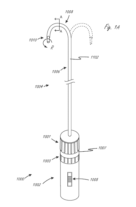
[00095] Figure lA illustrates an exemplary embodiment of a system that
integrates
steering and a medical device. System 1000 includes handle assembly 1002 and
steering
and medical device portion 1004. Steering and medical device portion 1004
includes a
proximal portion 1006 and steerable portion 1008. The system is adapted so
that handle
assembly 1002 can be actuated to cause steering of the steerable portion 1008,
and
optionally can be further actuated to cause movement of medical device 1010
relative to
steering and medical device portion 1004. In this exemplary embodiment, handle
assembly
1002 includes first actuator 1001, second actuator 1003, and third actuator
1005. First
actuator 1001 is adapted to be actuated (in this example rotated) relative to
handle body
1007 to cause the steering of steerable portion 1008, and specifically
steering outer sheath
1102. Steerable portion 1008 in this embodiment can be steered, or bent, into
the
configuration shown in Figure lA in solid lines, and can also be steered into
the
configuration shown in dashed lines, or anywhere in between, and in some
embodiments the
opposite steering function is limited to simply straightening the shaft from
an initial bent
configuration, such as the solid line bent configuration in figure 1A. The
term "steer" in this
disclosure means to deflect or bend, optionally via actuation of at least one
pull wire, but in
-12-
CA 03057946 2019-09-24
WO 2018/182836
PCT/US2018/015061
some instances the term can include shaft rotation (torqueing) and axial
movement. The
term "pull wire" herein refers to any element that may transmit a tensile
force from the
proximal end of the device to the distal end region. Pull wires may be
comprised of metal
wire such as stainless steel or nickel titanium, either solid or
stranded/braided, or it may be
comprised of a polymer such as aramid fiber (Kevlar0), polyethylene, ptfe,
eptfe, etc.,
preferably stranded/braided, but also in monofilament form. In a preferred
embodiment, the
pull wire is constructed from an aramid fiber bundle having four 50 denier
multifilament
(approximately 25 filaments) threads braided together at a high picks per
inch. The wire
cross-sectional diameter is typically in the .005"-.012" range, more
preferably .008"-.010",
although braided or stranded wire may flatten or ovalize in the device lumen.
The preferred
construction embodiments are believed to provide optimized strength and wear
resistance
for the size necessary to keep the shaft diameters to a minimum. Optional
second actuator
1003 is adapted to be actuated relative to handle body 1007 (in this example
rotated) to
cause rotation of medical tool 1010 relative to shaft 1102 (labeled as
rotation movement
"R"), and optional actuator 1005 is adapted to be actuated relative to handle
body 1007 (in
this example axially) to cause axial (distal-proximal) movement of medical
device 1010
relative the outer sheath 1102. Proximal portion 1006 is not configured to
bend
significantly when steerable portion 1008 is steered (bent/deflected),
although the proximal
portion may flex and bend to conform to the anatomy within which it is used.
In many
embodiments, this is accomplished by constructing the steerable portion 1008
from a softer
or less rigid material and/or composite construction than the proximal portion
1006.
[00096] The embodiment shown in Figure lA is an example of an apparatus that
includes
an integrated handle assembly that is in operable communication with both a
steerable outer
shaft and an inner medical tool. The handle assembly is integrated in that it
is assembled and
constructed to be in operable communication with the outer shaft and the inner
medical tool
prior to packaging and use. "Integrated" as that term is used in the context
of an integrated
handle assembly refers to a handle assembly in which at least one part of the
handle
assembly has to be broken or taken apart before the medical tool can be
removed from
within the outer shaft.
[00097] Figure 1B illustrates an exemplary cross section A-A (shown in Fig.
1A) of the
steering and device portion 1004, and specifically in the steerable portion
1008. In this
embodiment medical device 1010 is sized and configured to be disposed within a
steerable
sheath. The steerable sheath includes an outer shaft 1102 and a set of pull
wires 1104, which
are axially fixed in a distal region of steerable portion 1008.
-13-
CA 03057946 2019-09-24
WO 2018/182836
PCT/US2018/015061
[00098] The medical tool in figures lA and 1B can be, for example, any medical
tool
herein, such as an ultrasound tool. When "ultrasound probe" is used herein, it
generally
refers to an elongate tool that includes at least one ultrasound transducer
and one or more
conductive elements that electrically connect the at least one ultrasound
transducer to a
proximal region of the elongate tool. A proximal region of the ultrasound
probe includes, or
is modified to include, at least one proximal contact, which is in electrical
communication
with the at least one ultrasound transducer, and which can be put into
electrical
communication with, optionally via attachment to, an electrical contact on
another device,
cable, or connector.
[00099] Figure 2 illustrates an exemplary system 10 that is adapted to
function similarly to
the system in figures lA and 1B, and also illustrates exemplary internal
components of
handle assembly 12 (internal components shown as dashed lines). Handle
assembly 12 is
integrated and in operable communication with outer steerable shaft 20 and
medical tool 30.
Handle assembly 12 includes actuator 14 that is adapted to, when actuated
relative to handle
body 15, cause steering of steerable shaft 20. Actuator 14 is in operable
communication with
steerable shaft 20 via steering control 16 disposed in handle assembly 12.
Medical tool 30
includes a proximal portion 18 disposed within and incorporated into handle
assembly 12.
Actuator 13 is in operable communication with medical tool 30, and actuation
of actuator 13
(in this example rotation) relative to handle body 15, causes rotation of
medical tool 30
relative to outer shaft 20 via rotation control 1215. Optional third actuator
17 is also in
operable communication with medical tool 30, and is adapted to be actuated, in
this
embodiment, axially (relative to handle body 15), to cause axial movement of
medical tool
relative to outer steerable shaft 20 via axial control 1217.
[000100] The medical tool in figure 2 can be, for example, any medical tool
herein, such as
25 an ultrasound tool.
[000101] Figures 3 and 4 illustrate an exemplary embodiment of a system 1200
in which
the steerable portion can have a cross section as shown in Figure 1B. System
1200 includes
steerable portion 1202 and medical tool 1204, both of which are configured to
interface with
each other. Steerable portion 1202 includes handle portion 1206 and a sheath
portion 1208,
30 which includes steerable portion 1222. Sheath portion 1208 includes an
outer tubular
member 1207. Medical tool 1204 includes handle portion 1210 and tool portion
1212,
which includes at least one shaft and a working distal region at its distal
end. Handle
portion 1206 includes steering actuator 1220, which in this embodiment is
adapted to be
rotated relative to handle body 1209 to cause the steering of steerable
portion 1222.
-14-
CA 03057946 2019-09-24
WO 2018/182836
PCT/US2018/015061
[000102] Medical tool 1204 is configured to be advanced through steerable
portion 1202,
both of which are configured to interface with each other. When advanced, tool
portion
1212 of medical tool 1204 is advanced through sheath portion 1208 until its
distal end is
near the distal end of sheath portion 1208, and a portion of handle portion
1210 is advanced
distally within handle portion 1206. Handle portion 1210 of medical tool 1204
includes
handle 1214 and stabilizer 1218. Stabilizer 1218 is configured, along with an
internal
portion of handle portion 1206, to interface one another in a secure
relationship to prevent
relative movement therebetween in at least one direction. Handle portion 1210
also includes
nut 1216, which is configured to interface with a proximal end of handle
portion 1206.
Stabilizer 1218 acts as an axial constraint for medical tool 1204, relative to
steerable sheath
1202.
[000103] Figure As shown in Figure 4, a distal working region of tool portion
1212 is
extending distally out of sheath portion 1208 when the medical tool 1204 and
steerable
sheath 1202 are stably interfacing with one another. In this embodiment the
distal end of
tool portion 1212 is not axially fixed relative to the distal end of sheath
portion 1208.
[000104] The medical tool in figures 3 and 4 can be, for example, any medical
tool herein,
such as an ultrasound tool.
[000105] Handle 1214 can optionally include at least one actuator that can
cause the axial
and/or rotational motion of the medical device relative to the steerable
sheath. Thus, once
the tool and sheath are stably interfaced, one or more tool handle actuators
can control
motion of the medical tool (e.g., rotational or axial). The tool and sheath
can be interfaced
after packaging and just prior to use, or they can be integrated before
packaging. Handle
1214 can also include other controls that control the functionality of the
medical tool.
[000106] Figures 5 and 6 illustrate an exemplary distal region of a steerable
system that
includes an inner medical tool. System 1300 includes steerable sheath 1302 and
medical
tool portion 1304. Steerable sheath 1302 includes outer member 1308 and one or
more pull
wires 1306, which are fixed distal to the steerable portion and configured
such that, when a
handle actuator is actuated, they are moved axially proximal to the steerable
portion, which
causes their relative axial movement in the steerable portion, which causes
the steerable
portion to be steered (as is described above). Pull wire 1306 can be parallel
to the central
axis in the steerable portion of the sheath.
[000107] In this merely exemplary embodiment, tool portion 1304 includes an
elongate
medical tool 1310 that includes an RF tip electrode at its distal end, and a
guidewire lumen
1312, but the medical tool can be any other medical tool herein. In this
embodiment tool
-15-
CA 03057946 2019-09-24
WO 2018/182836
PCT/US2018/015061
1310 and steerable sheath 1302 are configured so that the tool distal end
(including the
region very near the distal end) is axially immovable but rotationally movable
relative to the
steerable sheath 1302 distal end (including the region very near the distal
end). To make the
parts axially immovable and rotationally movable, outer member 1308 includes
an extension
1314 that extends radially inward relative to the inner surface of outer
member 1308
proximal to extension 1314. Tool 1310 includes a region with an outer
configuration 1315
(radially inwardly shaped) that corresponds to the extension 1314. The two
components
similarly have shaped elements 1317 and 1318 distal to elements 1314 and 1315.
The
configuration of the tool and outer member therefore prevents distal and
proximal
movement of the tool relative to the outer member and therefore the steerable
sheath when
the tool and sheath are interfaced as shown. In this embodiment tool 1310 is
rotationally
free, or moveable, relative to steerable sheath. That is, while tool 1310
cannot move axially
at the fixation location (which is distal to the steerable portion) it can be
rotated. Being
rotationally free can be beneficial if the medical tool, including one or more
instruments
thereon, should be oriented in or facing a particular direction.
[000108] Because the tool and the sheath are axially fixed distal to the
steerable portion, the
proximal end of the tool is configured to be able to move slightly axially
during steering.
For example, a spring built into the handle can allow the tool shaft to move
slightly relative
to the steerable sheath. Other ways of allowing for proximal axial movement
can be
incorporated as well.
[000109] The proximal end of system 1300 can include the two handle components
such as
those shown in the embodiment in Figures 3 and 4, and can be similarly
interfacing, with the
exception of the moderate axial movement of the tool at the proximal end.
[000110] In other embodiments the distal region shown in figures 5 and 6 can
be
incorporated with a handle assembly shown in figures 1A or 2.
[000111] One aspect of the disclosure is a method of rendering two co-axial
components
that were previously axially movable axially immovable (axially fixing them).
This aspect
also includes methods of removing the axial fixation such that the components
can again be
axially moved. This can be considered releasable axial fixation. The axial
fixation is
created, in general, prior to advancing the system into a patient, and in some
embodiments
the axial fixation is created during manufacturing. The release of the axial
fixation can occur
during a refurbishing process, and the axial fixation can again be created
during a
refurbishing process.
-16-
CA 03057946 2019-09-24
WO 2018/182836
PCT/US2018/015061
[000112] In some embodiments the system can be modified to include a component
whose
volume can be modified (increased or decreased) to cause the axial fixation of
the medical
tool. In some embodiments the component has a configuration that changes to
cause the
axial fixation of the medical tool.
[000113] In some embodiments system 1300 is adapted so that extension 1314 is
configured such that its volume can be modified to cause or release the axial
fixation. In
this particular modification, fillable annular volume 1319 (shown and labeled
only once in
the cross-section but it is understood that it exists on the other side due to
its annular
configuration) is adapted to be filled with a filling material, and such that
the filling material
can be removed as well. In these alternative embodiments the outer member
includes an
annular filling volume 1319 defined by the radially outer dotted line surface
and by the
radially inner portions of the previously described extension 1314. That is,
extension 1314
is modified to include a fillable annular chamber or volume 1319, but outer
surfaces of
extension 1314 remain and define the annular fillable volume 1319.
[000114] When it is desired to allow tool 1310 and sheath 1302 to be
relatively axially
movable, such as during manufacture of the system, fillable volume 1319
remains at least
partially un-filled, so that tool 1310 can be easily advanced or retracted
axially within sheath
1302. When it is desirable to render tool 1310 and 1302 axially immovable, or
fixed, (after
they are in desired relative axial positions ¨such as during manufacturing or
refurbishment),
fillable volume 1319 is filled with a filling material so that the extension
extends radially
inward and becomes more rigid, preventing the axial movement of tool 1310
relative to
sheath 1302. The extension in this embodiment is thus a reconfigurable axial
restraint.
[000115] If it is desirable to axially move the tool 1310 and sheath 1302 at a
later time
(such as during refurbishment ¨ e.g., at least one of cleaning and
sterilizing), the fillable
material can then be removed from volume (or chamber) 1319, making extension
less rigid,
so that tool 1310 can be axially moved relative to sheath 1302.
[000116] In these alternative embodiments extension 1314 can be considered
expandable
and unexpandable; fillable and unfillable; reconfigurable; configured and
adapted to have a
stiffness that can be modified; configured so that its rigidity can be
modified; and having a
volume that can be modified.
[000117] In some embodiments the fillable material can be inserted and removed
from
annular fill volume 1319 with a fill device such as a needle.
-17-
CA 03057946 2019-09-24
WO 2018/182836
PCT/US2018/015061
[000118] In one exemplary use, tool 1310 is axially advanced to the position
in figure 6,
and fill volume 1319 is thereafter filled with a filing material to axially
fix tool 1310 and
sheath 1302 (e.g., during manufacture or refurbishment). The method can also
include
removing the filling material and axially moving at least one of the tool 1301
and sheath
1302 (e.g., during refurbishment).
[000119] In an exemplary embodiment the filling material can be modified from
a solid to
liquid, and visa-versa, by changing its temperature. In some embodiments the
fillable (also
referred to herein as "filling") material is solid at operating temperature to
increase the
volume or rigidity of extension 1314, but can be melted (or made less viscous)
to allow it to
be removed from annular volume 1319.
[000120] In some embodiments the filling material is a wax. The wax can, in
some
embodiments, have a melting point less than a polymeric material of an
adjacent
component, such as an inner or an outer member.
[000121] This concept of creating axial fixation (and allowing removal of the
axial
fixation) by, for example, adding and removing a filling material, can be used
to axially fix
any two components herein, including an outer sheath of a steerable sheath and
the medical
tool within it.
[000122] Figures 7A-7E represent exemplary embodiments of a distal region of
the sheath
portion 1208 of steerable sheath 1202 in system 1200. For simplicity, the
illustrated cross-
sections show only the outer sheath 1208 and not the inner tool 1212. The
outer sheath 1208
preferably has a composite construction to improve torque transmission applied
to the
outside of the shaft from the proximal end, or to resist torque forces applied
to it from within
the shaft, such as from tool 1212. As illustrated in Figure 7Ai-iii, in order
to form the
composite, multiple braid elements 1250, preferably formed from metal wire
(round, pairs
of round, or ribbon shaped) and/or multiple fibers (e.g., aramid or nylon),
may be braided
directly over a thin wall (e.g., .0010" .0005") lubricious liner tube 1251,
such as a PTFE
or FEP material. A thermoplastic polymer 1252 (such as Pebax in a range of
durometers
from 25D-72D, or nylon, or other common catheter materials) may be laminated
with heat
using heat shrink tubing (such as FEP) to reflow the polymer over the braid
elements 1250
and liner tube 1251 to form a uniform member. The thermoplastic polymer 1252
may also
have radiopaque compounds that include materials such as bismuth, barium
sulfate, or
tungsten in order that the tip of the sheath be visible to the user under
fluoroscopy. In the
embodiment of Figure 7Ai-iii, the pull wire 1104 is preferably parallel to the
central access
in the steerable (deflectable) portion 1222 of the sheath and also preferably
provided in a
-18-
CA 03057946 2019-09-24
WO 2018/182836
PCT/US2018/015061
lumen 1253 created within the wall of the steerable sheath 1208. This lumen
may be
created during the thermoplastic polymer tubing extrusion process or during a
shaft heat
lamination fusing process with the aid of a removable mandrel. The pull wire
lumen 1253
may further be created by incorporating a pull wire tube 1254, preferably
temporarily
supported by a removable mandrel, within the wall. The removable mandrel may
also be
placed alongside the pull line 1104 or 1104' during the fusing process,
resulting in a
somewhat ovalized lumen 1253 within which a fiber pull wire may be allowed to
flatten
into, allowing space for free movement of the pull wire. The tube 1254 may
include PTFE,
FEP, polyimide, or another material which maintains its wall integrity during
a heat
lamination process up to approximately 500 F. The tube is preferably
surrounded and
supported by the thermoplastic polymer 1252 which is preferably heat laminated
against the
tube. In another embodiment, the pull wire lumen, preferably comprising the
pull wire tube,
is incorporated within the weave of the braid elements 1250. For example,
braid elements
1250 running in one direction would pass under the pull wire lumen, while
those running in
the opposite direction would pass over the pull wire lumen. The braid
reinforcement
provides a more dimensionally stable lumen during catheter manipulations and
also helps
assure the straightness of the lumen as needed. Proximal to the steerable
portion, the pull
wire may continue proximally parallel to the central axis on the same side of
the outer
sheath 1208, such as is illustrated in Figure 7Ai-iii. In this embodiment and
others that
follow, an additional pull wire 1104' within an additional pull wire lumen
routed within the
wall of sheath 1208, up through the steerable portion 1222, may be required to
straighten the
steerable portion of the device. This straightening pull wire 1104' is
preferably routed
within steerable portion 1222 on the side opposite from the pull wire(s) 1104
used for
steering (deflection) in the steerable portion 1222. In another embodiment,
not shown, two
lumens and two straightening pull wires 1104' could be used, essentially
mirroring the
paired 1104 pull wire configuration. These straightening wires could also be
constructed to
allow deflection in the opposite direction by tensioning a greater distance
(beyond just
straightening) within the handle.
[000123] During use, a portion 1223 of the distal catheter just proximal to
the steerable
(deflectable) portion 1222 may be forced to conform to a curve based on the
constraints of
the anatomy in which it is used. For a specific embodiment where the device is
advanced
into the heart chambers from a groin access, the portion 1223 forced into a
curve is expected
to range from 5 to 25 cm in length. During rotation of the sheath shaft 1208
from the
proximal end, torque is transmitted through this distal curved region 1223 to
the catheter tip.
A non-uniform cross section and/or tension of the device in this region 1223
may induce a
-19-
CA 03057946 2019-09-24
WO 2018/182836
PCT/US2018/015061
tendency for the shaft to build up and suddenly release torque, causing a
"whip" or sudden
jerk in rotation as it is torqued. To minimize the potential for whip, it is
optional to
distribute the pull wire tension and construction material around the surface
of the curved
region 1223. In one embodiment, such as is illustrated in Figure 7Bi-iii, the
pull wire 1104
may spiral around the central axis of the sheath in at least the curved region
1223 proximal
to portion 1222. The pull wire of this embodiment may make a full
circumferential wrap
over approximately 10 cm of length, with this value ranging 5-15 cm. The
spiral may only
need to be present in the curved region 1223, continuing straight proximally
thereafter
through proximal portion 1224 (similar to 1006), which may minimize the
friction in the
pull wire lumen and the associated pull wire force required to steer (deflect)
the steerable
portion 1222. The spiral may also make a minimum of one turn before continuing
straight,
or spiral the full length of the shaft. In another embodiment to minimize
whip, it may only
be necessary to distribute the pull wire tension to opposite sides of the
shaft. As illustrated
in Figure 7Ci-ii, deflection of the steerable section 1222 is accomplished
with two parallel
pull wires 1104 positioned adjacent one another on the same side of the sheath
1208. In the
curved region 1223 and proximal portion 1224 (similar to 1006) proximal to the
steerable
section 1222, the pull wires are routed to opposite sides of the shaft, each
90 from the
position in the steerable section 1222, to distribute the tension more evenly.
While it is
preferable to actuate the two parallel pull wires at the same time with equal
force with the
handle actuator, in other embodiments, a differential in force could be
applied to steer the
tip to one side or the other of the plane formed when the two are actuated
with equal force.
In other embodiments, any plurality of pull wires could be routed in the same
configuration
as illustrated in Figures 7B or Figure 7C, with the multiple proximal pull
wires distributed
uniformly around the shaft circumference. Also, as illustrated in Figure 7Ci-
ii, the pull wires
1104 may be routed proximally along the opposite sides of the shaft for most
of the shaft
proximal portion 1124 length, but preferably brought back together adjacent
one another
near the proximal end portion of the shaft to allow the wires to exit the same
side of the
proximal shaft together to facilitate them being secured together to a handle
component for
simultaneous actuation tension.
[000124] Figures 7Di-iv illustrate another embodiment of the distal region of
catheter with
construction similar to that previously described, but instead configured to
provide a distal
steerable portion 1222 which can be deflected into two different directions.
As illustrated, a
two pairs of pull wires 1105/1107 and 1106/1108 are along the proximal shaft
region 1224
and curved region 1223. This is similar to Figure 7Ai-iii, except that the
wires are paired on
each side of the shaft. The routing could also be spiraled as in Figure 7Bi-
ii, or other
-20-
CA 03057946 2019-09-24
WO 2018/182836
PCT/US2018/015061
configurations discussed. Within distal steerable portion 1222, the wires are
routed 900
from the proximal portions, although other angles are contemplated. At a
junction 1225
within 1222 one or more of the pull wires (e.g., 1105 and 1107) may be
terminated and
anchored to the shaft, with the remaining pull wires (e.g., 1106 and 1108)
continuing to a
more distal tip location 1226 where they are anchored. This configuration
allows
independent actuation of pull wires terminated at 1225 and 1226 such that
different shapes
may be created during actuation. Figure 7Dii shows both lines 1107 and 1108
tensioned to
create a variable curve in the same direction. Figure 7Diii shows lines 1107
and 1106
tensioned to create an "S" curve. Other configurations are also possible.
[000125] The pull wires (such as 1104 and 1104') must be terminated at their
distal end in a
manner that reliably affixes them to the wall of the distal steerable shaft
portion 1222, such
that they do not break or pull free under repeated applications of tension. In
a preferred
embodiment, shown in Figure 7E, the pull wires 1104 and 1104', upon exiting
the distal pull
wire lumen 1253, are circumferentially interwoven into the braid wires 1250 of
the distal
shaft 1222 (shown without the thermoplastic polymer 1252). One or more of the
pull wires
1104 or 1104' may also be additionally or instead wrapped and/or tied around
the outside of
the braid wires 1250 for additional securing. The braid wires 1250 may be then
trimmed
distal to the securing point, with the interwoven and/or wrapped pull wires
preventing the
braid wires from expanding and/or unraveling. Additional adhesives such as UV
cured or
cyanoacrylates may also be used to secure the pull wires to the braid wires.
The weave
and/or wrap of the pull wires and braid wires is then laminated with a
thermoplastic polymer
which melts within the space around the wires and cools to secure them in
place. The
thermoplastic polymer may also have radiopaque compounds that include
materials such as
bismuth, barium sulfate, or tungsten in order that the tip of the sheath be
visible to the user
under fluoroscopy.
[000126] In additional embodiments, the tool 1212 may also or alternatively be
constructed
with one or more pull wires to deflect the tip in a manner similar to any of
the previous
embodiments described for the outer sheath 1208. In addition to routing the
pull wires
within the wall of the tubular member of the tool 1212, the pull wires could
be routed next
to the conductors inside the lumen of the tubular element 1212. Actuation of
the pull wires
could be from an actuator located in the proximal handle 1206. The distal
shaft of tool 1212
may also be formed into a particular shape (e.g., an arc) such that it bends
into the shape as
it exits the tip of the steerable portion 1222 of outer sheath 1208. The
stiffness of the distal
shaft of tool 1212 is such that it does not substantially deform outer sheath
1208 while
-21-
CA 03057946 2019-09-24
WO 2018/182836
PCT/US2018/015061
inside, but upon exiting is allowed to bend. The shape may be set by any one
or
combination of the following means: heat setting the polymeric material, using
a moveable
or fixed shaped stylet within the inner lumen of shaft 1212 or within a lumen
within the wall
of shaft 1212. Such a stylet could be round, oval, or rectangular in cross
section, and be
formed of stainless steel, nitinol, or a rigid polymer such as PEEK, Vestamid,
or similar.
The outer steerable sheath could alternatively be made to bend with a similar
method as
above, with or without additional pull wire deflection, and with or without
additional shape
or deflection of the distal portion of tool shaft 1212.
[000127] Fig. 8 illustrates a system 1400 comprising a medical tool 1204
disposed partially
inside a steerable sheath 1202. Medical tool 1204 and sheath 1202 can be any
of the
medical tools and sheaths described herein, even though they are labeled 1204
and 1202.
While the steerable sheath 1202 is preferably "steerable", for example through
the use of a
pull wire or other functional deflection mechanisms (any of those set forth
herein), it is
understood that this "steerable" sheath (or any steerable sheath herein) could
also be non-
steerable in that it is just a straight tubular element, or has a fixed, non-
deflectable distal
curve shape. Steering may be also accomplished via torqueing the sheath, with
or without
use of a deflection mechanism.
[000128] The system 1400 illustrated in figure 8 is designed to have modular
components
that are provided to the user in an integrated manner, but which can be
disassembled after a
procedure using a specialized process to clean, repair, and/or replace any of
the modular
components of the system. The system 1400 may then also be reassembled,
sterilized and
repackaged. This process, or in some cases a portion of this process, can be
referred to
herein as "reposing," or "refurbishment," and any system herein can be reposed
or
refurbished using any of the methods herein. The performance of system 1400 is
optimized
for the medical tool 1204 and sheath 1202 to work only with one another and
not substitute
other devices on the market that may have a similar function. Also, the
reposing of the
devices takes special care to ensure the continued safety and performance
quality of the
system.
[000129] In the disclosures that follow, many references are made to ways of
separating
various modular components of a system, either by breaking or using a
controlled process.
Depending on the embodiment, handle portion 1960 (see figures 9A and 9B), rear
handle
1961 (see figure 11), and handle lip 1962 (see figure 12A) can be separated
from the handle
assembly. Tool lock 1955 (e.g., shaft 1240 shown in figures 42 and 43), for
example, can
be separated from tool portion 1212 of medical tool 1204 or from handle
assembly 1206.
-22-
CA 03057946 2019-09-24
WO 2018/182836
PCT/US2018/015061
Tool connector 1210 (see figure 8) or 1990 (see figure 13A), for example,
could be
separated from tool portion 1212. Hemostasis valve 1950 assembly (see figure
8) could be
separated from the handle assembly 1206. Sheath portion 1208 could be
separated from
handle assembly 1206. Outer member 2010 (see figure 17B) of tool portion 1212
could be
separated from inner lead assembly 2011 and its internal electrical
connections. Many
similar controlled processes and materials could be used to enable the initial
assembly and
subsequent disassembly and reassembly of the components of any of the
embodiments
herein.
[000130] Any given process or combination of processes could be used at any
one or all the
aforementioned modular separation points. The processes include but are not
limited to the
following examples. Components could be bonded using a material that acts like
an
adhesive or mechanical lock, but which can be deformed with heat to remove the
components. This includes materials such as wax and thermoplastic elastomers
(polyurethane, polyethylene, polyamide, to name just a few). Materials such as
hydrogels
(such as those described previously herein) may be swollen with aqueous
solutions to
change their properties such that they soften or become lubricious enough to
separate
components. Sugar, salt, starch, or other similar materials in crystal or
powder form could
be used to create a mechanical interference fit between components, but then
readily
dissolved in an aqueous solution to separate the components. These materials
could also be
used as a matrix in a non-degradable material that then compresses like a foam
once the
crystalline structure is dissolved. Other polymers known to break down over
time after
contact with fluid (such as that introduced during use), including those also
known in the art
to be biodegradable, could be used in the system such that replacement due to
their
weakened properties would be mandated. Other materials could be used that lose
their
holding strength in the presence of a chemical solvent. Strong acids or bases
could be used
to dissolve certain metals and plastics. For example, silicone may swell and
tear easily in
the presence of heptane, hexane, or isopropyl alcohol. Where a liquid material
is to be
dispensed to alter the seal, the seal could be protected during use inside a
protective space
which can only be accessed with a special tool (such as a needle puncture
diaphragm or luer
activated valve).
[000131] Certain components may be joined using a solder or solder-like
process, where
reheating the solder will separate the components. In some embodiments the
metallic joint
could be separated using electrolysis. Mechanical interference could also be
used to hold
components together (e.g., screws, pins, thread, wedge, and the like).
Ratcheting
-23-
CA 03057946 2019-09-24
WO 2018/182836
PCT/US2018/015061
mechanisms (e.g., Zip-ties, belt-loop styles, roller-wedge, cam-actuated
grips) could also be
used to hold components together but require a manufacturer access to the
parts to break and
replace or use a tool to temporarily separate the components. Components could
be held in
place through magnetic attraction (magnet to magnet or magnet to iron). In
particular
embodiments, the magnetic hold could not be released without demagnetizing the
magnets.
This could be accomplished by physical breaking or mechanically fatiguing the
magnet,
raising the temperature of the magnet above its Curie Point (e.g., 80 C for
neodymium
magnets), or applying an alternating current across the magnet to disrupt the
dipoles. In
another embodiment, parts could be engaged and held in place with a lock such
as a bar fit
into a hole or other capture feature (similar to a door lock). The bar could
be heat set in a
curve, or a hinge structure, that is normally engaged in the hole, but upon
exposure to heat
beyond a transition temperature, changes shape to back out of the hole
(allowing parts to be
disassembled). In a similar manner, the bar could be magnetized and when
exposed to a
magnetic field, forced out of the hole. Other similar mechanisms could use
coils or other
springs, or spring-actuated devices, which change shape in the presence of
heat or a
magnetic field to unlock. In another embodiment, components could be held
together under
hydraulic pressure (e.g., water or oil such as mineral oil or silicone oil),
such as a sealed
cylinder with a piston, a bellows, diaphragm, balloon, etc. To separate the
components, the
pressure may be vented by puncturing into or otherwise breaking the seal to
the pressurized
chamber. Opening or relaxing a valve to relieve the pressure could also be
employed. In
many cases, the process used to separate the parts will also contaminate or
damage them
enough to require replacement, further repair, and/or additional cleaning
before reassembly
and other subsequent processing steps. Any combination of the exemplary
processes above
could also be used.
[000132] In any of the embodiments herein, a medical tool can be an ultrasound
device,
with one or more ultrasound transducers disposed at its distal region. For
example, the
ultrasound device may be an ultrasound imaging device, such as a 4D-ICE
(intracardiac
echocardiography) imaging tool.
[000133] Figure 8 illustrates that tool portion 1212 of the medical tool 1204
may be
rotatable within and relative to steerable sheath 1202 and may also be
optionally capable of
axial translation within the sheath. Tool lock 1955, which in figure 8 is
disposed within the
body of handle 1206, is secured to tool portion 1212 and may have one or more
functions to
constrain movement within sheath 1202 and/or control the functionality of
medical tool
1204 (e.g., shaft 1240 in figures 42 and 43). In some embodiments of
constraining the axial
-24-
CA 03057946 2019-09-24
WO 2018/182836
PCT/US2018/015061
motion of tool 1212 in the proximal direction, the tip of the tool 1212 may be
prevented
from entering inside the sheath where it may be rendered non-functional (e.g.,
if the purpose
is to deliver electrical energy to the tissue or send/receive ultrasound
pulses). In other
embodiments, a luminal seal may be provided on tool 1212 just proximal to the
functional
portion of the distal working end, which when retracted into a particular
location within the
distal luminal space of sheath 1208, defined by the proximal retraction limit,
a seal within
the lumen is formed. In other embodiments where the distal end region of tool
1212 is
larger than the ID of the sheath, as is illustrated with tip 1821 in Figure
13A, the proximal
limit may prevent damage to the sheath, other devices, or tissue if the tool
tip is retracted
against the distal tip of the sheath portion 1208. The proximal travel limit
of tool 1212
provides a slight offset (e.g., 0.5-3.0 mm) between the proximal end of tip
1821 and the
distal end of sheath portion 1208, which may be beneficial to allow space for
flushed fluids
to the exit the sheath lumen and/or avoid pinching tissue structures or
interventional devices
between the tip 1821 and sheath 1208 when the tip is pulled back close to the
distal end of
the sheath 1208.
[000134] Constraint of axial motion of the tool 1212 in the distal direction
may be
necessary to ensure adequate control of the tool 1212. For example, too far of
an extension
without distal steering may cause inadvertent damage to tissue structures by
the user, or the
tool 1212 could become too floppy to torque and steer with adequate precision
using the
system 1200, limiting its performance. The use of a tool lock 1955,
constrained within the
handle 1206, to limit axial motion will also have practical limits for the
length of handle
1206. With the above considerations in mind, an optional practical distal
extension limit of
the tool 1212 created by the interaction of tool lock 1955 in handle 1206
would be
approximately 3 cm. Other embodiments could be considered up to 5 cm tool
extension.
Other configurations with an extension of up to 20 cm to leverage advantages
of a floppy
tool shaft, or pre-shaped steerable tool shaft, or a deflectable tool shaft,
to track into various
anatomic structures are also contemplated. The elimination of a travel limiter
such as tool
lock 1955 would limit travel by the length of the tool shaft that has
sufficient clearance to
pass within the lumen of sheath portion 1208. Figure 8 also illustrates a
hemostasis valve
assembly 1950 within the handle portion 1206 which is useful to keep blood or
other fluids
from leaking out from the proximal end of steerable sheath 1202, and to allow
flushing of
the luminal space between tool 1204 and the inner lumen of sheath 1202.
[000135] Figures 9A and 9B illustrate another embodiment of a system where
handle
assembly 1206 includes a removable or breakable handle portion 1960 that can
be removed
-25-
CA 03057946 2019-09-24
WO 2018/182836
PCT/US2018/015061
from handle assembly 1206 or broken from assembly 1206 to allow access to an
interior
space of handle assembly 1206. Once removed or broken, as shown in figure 9A,
access is
available to tool lock 1955 disposed with handle assembly 1206. Tool lock 1955
can then
be disassociated from tool portion 1212, as shown in figure 8A. Once tool lock
1955 is
removed, tool 1204 is can then be removed from sheath 1202, as shown in figure
9B.
[000136] In some embodiments, handle portion 1960 (and any other handle
portion herein
that can be removed or broken from a handle assembly) can be configured to
interface with
a corresponding component of handle assembly 1206 so that it can be stabilized
relative to
1206 when in use, but can be removed from handle 1206 in a controlled manner
without
breaking an interface between handle 1206 and portion 1960. For example
without
limitation, the two parts could have a threaded interface. Alternatively, for
example, portion
1960 can be configured so that the interface between it and handle assembly
1206 must be
broken, but wherein the interface is such that breaking it can be done in a
relatively easy and
predictable manner.
[000137] One function of tool lock 1955 is to prevent removal of the medical
tool 1204
from sheath 1202 to ensure system integrity as previously stated. A tool lock
also limits the
axial translation of the medical tool within the handle assembly by being
physically
constrained within the handle assembly. This may be desirable to ensure the
medical tool is
either not moved axially, or the movement is constrained to a safe and
functional range for
the medical tool beyond the tip of the sheath.
[000138] In another embodiment, illustrated in figures 10A and 10B, tool lock
1955 and
handle assembly 1206 may both be configured to limit the range of medical tool
rotation.
This may be desirable to prevent a build-up of torque in one direction that
could twist and
damage portions of the outer member 2010 or an inner lead assembly 2011 (see
figures
17A-C).
[000139] As illustrated in figures 10A and 10B, tool lock 1955 has a feature
1956, in this
embodiment a radial protrusion on one side, that allows it to be rotated
through an angle less
than 360 in either direction. Handle assembly 1206 has a protrusion (disposed
at the
bottom of the figure) extending radially inward that is positioned and
configured to engage
with and stop movement of feature 1956, and thus tool lock 1955 and medical
tool 1212.
Other torque limiters known in the art, including those that limit torque to a
finite number of
full rotations in a given direction, could also be employed. Axial travel and
torque could
also be limited by opposing magnets. Resistance would be encountered as a
magnet in a
tool lock approached (via axial or rotational travel), an opposing magnet
positioned in the
-26-
CA 03057946 2019-09-24
WO 2018/182836
PCT/US2018/015061
handle portion. Rotational limitation, an illustration of which is shown
figures 10A and 10B,
can be incorporated into any of the systems herein.
[000140] Figures 42 and 43 illustrate an alternate exemplary medical tool
rotation limiting
mechanism in the handle. In that embodiment, the rotation limiter is a
compound rotation
limiter, is also disposed proximal to a hemostatic valve, and allows for
greater than 360
degree rotation of the medical tool shaft at the location of the rotation
limiter within the
handle.
[000141] In embodiments that include a tool lock, the tool lock rotational
and/or axial
movement may also have a friction fit with features within the handle such
that it is
moveable but does not rotate or slide back to the original position except by
action of the
user. For example, either or both the outer surface of the tool lock and an
inner surf ace of
the handle portion (such as handle portion 1960) may comprise a lubricious
material such as
PTFE, FEP, Delrin (Acetal). Unless formed from the same material, the mating
material
could be a smooth polished polymer or metal. The two parts could have a
precise clearance
or interference of, for example, up to .0002". The friction could also be
controlled by a
slight interference from just a portion of the surface of the tool lock with a
portion of the
handle portion (such as portion 1960). The interference could be a small
integrated feature,
and/or or a separate component which is mounted on an elastic material such as
a
compressible polymer (silicone, polyurethane, etc.), either solid or in foam
form, or a metal
or rigid polymer spring formed from a coil or flat ribbon. A slidable wedge
could also be
used to adjust the compression. The amount of compression interference could
also be
adjusted at the time of manufacture with a lead screw or a pressurized chamber
driving the
interference features together. During a reposing process this compression
friction
interference would need to be disassembled, and then reassembled and returned
to
manufacturer settings. In another embodiment, the compressive features could
be
assembled into the handle portion (such as portion 1960) to act directly on
the tool portion
1212 without the need for the tool lock feature. While the tool lock is
illustrated as
integrated into tool portion 1212, it could also be integrated directly in to
the tool handle
portion 1210, which would be engaged into the sheath handle portion 1960. This
is
particularly applicable where axial translation of the medical tool 1204
relative to the sheath
1202 is not required.
[000142] Tool lock 1955 may also have an electronic or electromagnetic feature
which
senses the presence of handle portion 1960 (or other handle portion). Once a
handle portion
(e.g., portion 1960) is removed, the tool lock may disable the functionality
of medical tool
-27-
CA 03057946 2019-09-24
WO 2018/182836
PCT/US2018/015061
1204. For example, the handle portion may include a magnet mounted in
proximity to the
tool lock. The magnet can hold a reed switch closed in the tool lock that
completes a
functional circuit in the medical tool. When the magnet is removed with the
handle portion
(e.g., portion 1960), the reed switch opens and disables the medical tool.
Other proximity
switches to accomplish the same function can also be used. The tool lock may
also or
alternatively disable the medical tool function once the tool lock is removed
from the
medical tool (e.g., as would be required to remove the medical tool from the
sheath). For
example, the tool lock could have a direct wired connection to the medical
tool (for
example, within the tool portion 1212) which disconnects from the medical tool
upon tool
removal. The medical tool could also include a proximity sensor in the tool
portion 1212
which is disabled once the medical tool is removed from the sheath. For
example, similar to
that described above, a reed switch completing a functional circuit in the
medical tool could
be held closed by a magnet in the tool lock. Removal of the tool lock would
then open the
reed switch and disable the medical tool. Other proximity sensors known in the
art could
also be utilized. Replacement of the tool lock could re-enable the function;
however, an
additional reprogramming of the controlling tool software may also be made
necessary to
reset function of the medical tool once the software detects an interruption
in the circuit. In
a related scenario, the removal or breakage of handle portion (such as portion
1960) could
interrupt a circuit in the tool lock which is sensed by the medical tool
and/or more
specifically, the controlling tool software. Function could then be restored
to the tool by
repairing, replacing, or reprogramming the tool lock, and the replacement
and/or repair of
the handle portion (such as portion 1960).
[000143] Figures 11A and 11B illustrate another embodiment of a system that
has modular
features to aid in reposing the device. In this embodiment, handle assembly
1506 may be
disassembled through removal or breakage of handle rear component 1961 from
the
remainder of handle assembly 1506. This allows access to a tool lock (not
shown but it
could any tool lock described herein) as well as hemostasis valve assembly
1950.
Depending on the configuration of the tool handle, the handle rear 1961 may be
removed
from the tool in the proximal direction (without removal of the tool lock), or
the tool lock
may be accessed more easily to remove the tool lock than the prior embodiment
where only
the handle portion 1955 was removed. In the present configuration hemostasis
valve
assembly 1950 may be accessed to remove and replace the valve assembly.
Alternatively
the valve assembly, including any of its individual components, could be
removed,
disassembled, cleaned, repaired, and replaced. Repair may only involve
replacement of
hemostasis seal 1951 in the assembly 1950. The seal could be of a slitted
silicone or other
-28-
CA 03057946 2019-09-24
WO 2018/182836
PCT/US2018/015061
soft polymeric compound known in the art, or any of the seals in this
disclosure. The
hemostasis valve assembly preferably includes a luer fitting 1952 on its
distal end such that
it could simply be pressed into and out of a mating luer fitting in the
handle. Alternative
fittings can also be used.
[000144] The steerable sheath 1202 may also be adapted to allow the sheath
portion 1208
to be separated from the handle assembly 1506. Similar to other modular
components, this
could allow removal for cleaning, repair, or replacement. Sheath 1202 may be
fitted with
tensile elements to deflect the catheter tip. Tensile elements similar to
these are illustrated
in figure 11B as elements 1970. The one or more tensile elements 1970 are
preferably
secured permanently to a fastener 1971, such as by a welding, soldering,
crimping, swaging,
or adhesive/epoxy bonding process. If potting the ends in an adhesive/epoxy,
the end of the
tensile element is preferably formed into an enlarged ball, coil, loop, or
other similar feature
larger than the cross-section of the tensile element itself. Alternatively,
the tensile element
may be releasably secured with a set screw or other mechanical fastener. An
enlarged
welded ball end or a separate tube crimped to the proximal end of the tensile
element may
aid in mechanical capture of the tensile element 1970 in the fastener 1971.
The fastener
1971 is configured to be acted on by an engagement feature 1972 and linked to
the steerable
actuator 1520. The engagement feature 1972 comprises a portion 1972' and 1972"
each
comprising a thread, one the reverse of the other. The actuator 1520 comprises
a dual
thread, one the reverse of the other, such that when actuator 1520 is rotated,
portions 1972'
and 1972" of the engagement feature are driven in opposite directions thereby
causing the
steerable section to deflect in one or another direction. The fastener may be
designed to be
readily disconnected and reconnected to the actuator for rapid and cost-
effective processing
during reposing. Alternatively, the tensile elements may be removably
connected directly to
the engagement feature without use of the fastener.
[000145] Figures 12A and 12B illustrate an alternative embodiment of an
integrated
medical device (e.g., ultrasound) or system 1700 that includes an integrated
handle
assembly, a steerable sheath, and a medical tool, and can be repurposed using
any of the
methods herein. In system 1700, the handle assembly 1703 is in operable
communication
with steerable sheath 1702 and medical tool 1704, the handle assembly 1703
including a
handle body 1705 with an outer surface positioned to be gripped by a user, a
first actuator
1720 adapted to be moved relative to handle body 1705, and a second actuator
1780 adapted
to be moved relative to handle body 1705. Steerable sheath 1702 has a distal
deflectable
region (not labeled) that is in operable communication with at least one pull
wire. In some
-29-
CA 03057946 2019-09-24
WO 2018/182836
PCT/US2018/015061
embodiments, medical tool 1704 is an elongate ultrasound device with a distal
portion that
comprises an ultrasound transducer, at least a portion of the elongate
ultrasound device is
disposed within steerable sheath 1702, the elongate ultrasound device is in
operable
communication with second actuator 1780. First actuator 1720 is in operable
communication with at least one pull wire such that actuation of first
actuator 1720 relative
to handle body 1705 causes deflection of the distal deflectable region of
steerable sheath
1702.
[000146] Second actuator 1780 is adapted to be rotated relative to handle body
1705 and is
also adapted to be moved axially relative to handle body 1705. Second actuator
1780 is in
operable communication with the elongate medical device 1704 such that axial
movement
of the second actuator relative to handle body 1705 causes axial movement of
elongate
medical device 1704 (distal and proximal) relative to the distal end of the
steerable sheath,
and such that rotation of second actuator 1780 relative to the handle body
1705 causes
rotation of elongate medical device 1704 relative to the distal end of the
steerable sheath, as
is shown as rotational movement "R" in figures 12A and 12B.
[000147] Axial movement of the tool relative to the sheath, if the tool is an
ultrasound
imaging tool, is generally desirable in that it improves the probe's ability
to image larger
regions of the body after the probe has been steered to a particular location
and allows the
operator to more easily refine the field of view once the probe has been
steered to a
generally viable location.
[000148] System 1700 also includes optional tool lock 1755. Tool lock 1755 is
contained
within handle assembly 1703 but coupled to second actuator 1780. Tool lock
1755 and
second actuator 1780 may be fitted with magnets, for example, to engage one
another.
Alternatively, one of the components could contain iron and the other a
magnet. Tool lock
1755 is firmly and releasably coupled to tool portion 1712 of medical tool
1704. Advancing
distally or retracting proximally second actuator 1780 moves tool lock 1755
distally or
proximally, respectively. The resulting axially movement of actuator tool 1755
causes
axially movement of medical tool 1704. Similarly, rotation of second actuator
1780
relative to handle body1705 causes rotation of tool lock 1755, which causes
the rotation of
medical tool 1704 (shown as rotation "R" in figures 12A and 12B). In this
embodiment, the
tool's axial movement (relative to the sheath) as well as its rotational
movement (relative to
the sheath) are limited within a fixed range of motion. In one embodiment, in
order to
remove medical tool 1704 from the steerable sheath 1702 (such as during
refurbishment),
handle rear lip 1762 could be removed or broken to remove tool lock 1755 (and
remainder
-30-
CA 03057946 2019-09-24
WO 2018/182836
PCT/US2018/015061
of the tool portion 1712) from handle 1706. In addition, second actuator 1780
could be
decoupled from tool lock 1755. This may require custom fixtures to pry the
coupled units
apart, or the use of a special tool to demagnetize or otherwise alter the
polarity (temporarily
at least) of either the outer coupler or tool lock. As described previously,
the tool lock may
contain a feature to disable the tool function when the magnet or other
proximity controller
is removed. Rear lip 1762 is an illustrative and optional component, and the
handle
assembly can have different parts.
[000149] Figures 13Ai-ii-13C illustrate an embodiment of a system in which the
medical
tool 1204 (which can also be any other medical tool herein) includes a
plurality of electrical
contacts 1992. Figures 13Ai and 13Aii illustrate the disassembled components.
Figures
13Bi and 13Bii illustrate tool portion 1212 back loaded into the sheath
portion 1208. Figure
13C illustrates proximal tool connector 1990 (which can be attached, directly
or indirectly
with an energy console) connected to tool portion 1212 so the tool portion
1212 is in
electrical communication with connector 1990. Tool portion 1212 is fitted on
the proximal
end with a plurality of mating electrical contacts 1992. Tool 1204 contains a
distal working
end 1821 (e.g., ultrasound imaging tool) which is larger in diameter than the
lumen of the
tool portion 1212, an illustration of which is shown in figure 13Bii. In this
embodiment the
outer dimension of tool portion 1212 and electrical contacts 1992 are sized to
pass through a
lumen of the sheath portion 1208, but the distal working end 1821 is too large
to pass
through the lumen. As a result, assembly of the tool through the sheath
portion 1208
requires the proximal end of the tool portion 1212 be advanced through the
distal tip of the
sheath and advanced proximally until the electrodes exit the proximal end of
the sheath
handle 1206. This construction helps minimize the outer dimension of the
sheath portion
1208 such that it is not necessarily larger than the distal working end 1821.
In certain uses
the distal working end may need to be at a maximum allowed dimension to
accommodate
electronic components and their connections, or, in certain applications,
minimize the
density of electrical current or acoustic energy to minimize overheating or
cavitation of the
tissue. The proximal electrical contacts 1992 may be discrete electrically
conductive
surfaces (e.g., discs, bars, strips, spheres, etc.), or circumferential or
partially circumferential
rings. In a preferred embodiment, the contacts are formed from the exposed
conductive
material of an otherwise insulated flex circuit (e.g. insulation is not
disposed over the
exposed conductive material). The mating contacts 1991 in the connector may be
similarly
designed to make contact. The contact surface may be annular or flat and
preferably is
spring loaded or otherwise mechanically compressed to make secure contact. The
handle
assembly in figures 13A-3C can be any of the handle assemblies herein; the
steerable sheath
-31-
CA 03057946 2019-09-24
WO 2018/182836
PCT/US2018/015061
can be any of the steerable sheaths herein; and the medical tool can be any of
the medical
tools herein. The front loading assembly can be used during the assembly of
any system
herein.
[000150] Figures 14A-14C illustrate an exemplary proximal portion of a system,
and which
can be the proximal portion of any of the systems herein. As illustrated in
Fig. 14A,
proximal contacts 1992 of the medical tool may be press fit into connector
1990 against the
contacts 1991. Alternatively, as illustrated in Fig. 14B, connector 1990' can
be adapted to
open up to receive contacts 1991 before it is clamped down over contacts 1991,
as shown in
the closed configuration of Fig. 14C. The connector 1990' can be sealed with
seal 1995
during manufacture. Seal 1995 may comprise, but is not limited to, a hydrogel,
a wax, a
silicone ring or gasket, or other means and combinations described previously
in this
disclosure. To repose the device, the connector 1990' contact must be broken
or carefully
disassembled to remove the shaft of tool 1212 in the distal direction through
the sheath
(such as a steerable sheath). Disassembly of seal 1995 may be accomplished by
heating and
melting the wax or other meltable substance, dissolving a dried material in an
aqueous
solution, and/or swelling a silicone with heptane or similar chemical
compound.
[000151] Figures 15A-15B illustrate a exemplary system similar to that of
Figs. 14A-14C
with the exception that the connector 1990" contains an inner feature 2000
designed to
stably interface with and enclose tool lock 1955 attached to tool portion
1212. Figure 15A
illustrates the system just before connection of the connector 1990" to the
tool portion
1212, and Fig. 15B shows a completed connection. While tool lock 1955 is
illustrated just
distal to the proximal tool contacts 1992, it could also be configured on the
proximal side of
the contacts, with a corresponding inner feature 2000 location proximal to the
connector
contacts 1991. As described previously, the tool lock may contain a feature to
disable the
tool function when the magnet or other proximity controller is removed. In
this
embodiment, the disabling feature may alternatively be built into the
connector 1990",
particularly within the inner feature 2000, where the circuit connection in
the cable leading
back to a control console is dependent on the state of the disabling feature.
Assembly and
disassembly of the portion of the connector containing feature 2000 could be
accomplished
by the means described previously for the connector 1990 in Fig. 15, the
handle portion of
Fig. 9, or the rear handle of Fig. 11. The handle assembly in figures 15A-B
can be any of the
handle assemblies herein; the steerable sheath can be any of the steerable
sheaths herein;
and the medical tool can be any of the medical tools herein.
-32-
CA 03057946 2019-09-24
WO 2018/182836
PCT/US2018/015061
[000152] In a variation of the embodiment in Figures 15A and 15B, the assembly
of tool
1212 may require the "back loading" of tool 1212 through the distal end of the
steerable
sheath portion 1208, as described in the embodiment of Figs. 13A-13C wherein
the outer
dimension of the tool and the electrical contacts are sized to pass through
the lumen of the
sheath portion, but the distal working end may not pass. In this embodiment of
Figures 15A
and 15B, the tool lock must be assembled after back loading the tool. During
reposing, the
tool lock would need to be removed to remove the tool 1212 from the sheath
portion 1208,
and repaired and/or replaced after cleaning and re-back loading the tool 1212
through the
sheath portion 1208. In an alternate version of the embodiment, the tool 1212
may be
assembled by "front loading" an insertion of the distal tip through the
proximal handle end
of sheath 1202. In this alternate embodiment of Fig. 15A and 15B, tool lock
1955 does not
necessarily need to be removable from the tool 1212.
[000153] As illustrated in Figures 15A-B, the clamping action of inner feature
2000 over
tool lock 1955 results in a mechanical engagement of the two features such
that axial
translation and torque may be transferred from the connector 1990" to the tool
1212. This
may provide the user with a more convenient means of gripping the tool 1212 to
manipulate
its position relative to the sheath 1202.
[000154] As illustrated in the exemplary system of Figure 16, a separate
torque device 2005
can be attached to the tool 1212 to provide a similar ability as above to
translate and torque
the tool 1212 relative to sheath 1202, but without the need to make a
connection to
connector 1990, as previously described in Figures 15A and 15B. The torque
device 2005
may also be engaged over tool lock 1955 to provide enhanced mechanical
engagement.
Torque device 2005 could also serve a purpose similar to the inner feature
2000 in that tool
function is dependent on the presence of the torque device 2005. As previously
described in
the embodiment of Figures 13A-13C, the torque device could be assembled onto
the tool
1212 such that removal of the tool 1212 from the sheath 1202 is not possible
without
breaking the torque device and/or tool 1212, or without the use of a custom
reposing process
to remove the torque device. The handle assembly in figures 16 can be any of
the handle
assemblies herein; the steerable sheath can be any of the steerable sheaths
herein; and the
medical tool can be any of the medical tools herein.
[000155] The embodiment of Figures 17A-C illustrates an exemplary medical tool
where
tool portion 1212 comprises an outer member 2010 and an inner lead assembly
2011. The
inner lead assembly further includes a distal working end 1821 and proximal
electrical
contacts 1992. The outer member 2010 may be assembled and disassembled from
the inner
-33-
CA 03057946 2019-09-24
WO 2018/182836
PCT/US2018/015061
lead assembly as part of the reposing process. The outer member 2010 can be a
tubular
structure capable of transmitting torque via, for example, a braided composite
construction.
Outer member 2010 is reversibly sealed and secured to the inner lead assembly
at locations
2015 and 2013 using processes previously described in this disclosure. Figure
17B shows a
larger view of the encircled region in figure 17A. Figure 17C shows inner lead
assembly
2011, distal working end, and proximal end removed from outer member 2010. The
handle
assembly in figures 17A-C can be any of the handle assemblies herein; the
steerable sheath
can be any of the steerable sheaths herein; and the medical tool can be any of
the medical
tools herein.
[000156] The disclosure below relates generally to electrical connections and
contacts in a
medical device, optionally an ultrasound probe if not otherwise specified. The
disclosure
that follows can apply to any of the systems, or aspect of the systems,
herein. The electrical
connections, contacts, device, and methods can be integrated into any of the
systems above,
such as, without limitation, the handle assembly in figure 12.
[000157] One aspect of the disclosure includes methods of disassociating at
least a portion
of the system from other components, optionally as part of a reposing process.
In some
embodiments the medical tool includes one or more electrical contacts that are
coupled to
other electrical contacts, which are in electrical communication with an
energy console, and
examples of consoles are known in the ultrasound art.
[000158] Figure 18 illustrates merely a portion of an exemplary medical tool,
such as an
ultrasound probe, that can be electrically coupled directly or indirectly to
an energy console,
such as an ultrasound console.
[000159] The embodiment shown in Figure 18 can be used in a manner similar in
concept
to the embodiment illustrated in Figures 13A-C, in that reposing the device
involves
disconnection of one or more proximal electrical contacts and moving the tool
portion
distally out of the distal end of the sheath portion. In this embodiment tool
portion 1212
comprises at least a tool outer sheath or member 2010, distal working end 1821
(which can
include at least one ultrasound transducer), and conductor bundle 2020. The
conductor
bundle 2020 extends from the distal working end 1821, through the tool outer
member 2010
to a proximal connector (the connector and handle mechanism are not shown in
Fig. 18 for
clarity). In some embodiments the medical tool is used for ultrasound imaging,
optionally
where the distal working end 1821 comprises a two-dimensional (2D) array of
piezo electric
components mounted on an ASIC (application specific integrated circuit).
-34-
CA 03057946 2019-09-24
WO 2018/182836
PCT/US2018/015061
[000160] Figure 19 illustrates a merely exemplary proximal end of a medical
device (the
medical device is shown on the right), and in this embodiment the medical
device is an
ultrasound probe. The proximal end 2015 of the medical device is adapted to be
electrically
coupled to connector cable 270, which is directly or adapted to be indirectly
electrically
coupled to an energy console, such as an ultrasound energy console. As
illustrated in Figure
19, conductor bundle 2020 extends from a distal region of the medical tool
(distal region not
shown) into a proximal connector 2015 within which is housed a rigid or
flexible printed
circuit board ("PCB") 2030. The connector bundle 2020 includes a plurality of
contacts
2024 (examples of which are described below) that are attached to PCB board
contacts
2031. Each individual trace from each contact 2031 is linked to individual
exposed contacts
2050 on another portion, optionally more proximal, of the PCB. The individual
PCB traces
may also pass through other useful circuitry on the PCB. The exposed contacts
2050 are
configured for a mechanical mating for electrical conduction to similar
contacts 2060 on
mating connector cable 2070, similar in concept to the proximal tool connector
1990
described previously, which links the tool 1204 to a user-interface console.
Proximal
connector 2015 can be incorporated into any of the systems, handles, steerable
sheaths,
medical tools, etc., herein, such as that shown in figures 12A and 12B.
[000161] Figures 20A and 20B illustrate an exemplary conductor strip (also
referred to
herein as a flexible circuit strip) 2021 that can be included in any of the
conductor bundles
herein. The embodiment in figures 20A and 20B is an example of a conductor
strip that can
be included in bundle 2020 from figures 18 and 19. The embodiment in figures
20A and
20B can be incorporated into any other system herein.
[000162] As shown in Figures 20A, 20B and 20G, conductor bundle 2020 comprises
a
plurality of flex circuit strips, including multi-trace strips 2021, as well
as conductive strips
for grounding 2022 and shielding 2023 (only a portion of which are shown).
Each multi-
trace strip comprises a plurality of conductive traces 2025, which can be seen
clearly in
figures 20B, 20C and 20D. The number traces 2025 in figures 20D-G is twelve,
and the
number of traces in figures 20A-20C is sixteen, and they are both exemplary as
to the
number of traces 2025 that can be used. Each strip 2021 can be approximately
.072" wide
and .0022" thick, and can optionally comprise sixteen .0022" wide x
about.0007" thick
conductive (e.g., copper) traces, each spaced approximately .0022" apart. The
traces are
disposed on an insulating substrate layer 2027, such as a polyimide substrate,
and the traces
can be at least partly covered by a cover layer 2026, such as a photoimageable
film cover
("PIG") layer or other dry film solder mask (DFSM) or other similar material.
The cover
-35-
CA 03057946 2019-09-24
WO 2018/182836
PCT/US2018/015061
layer generally extends along most of the bundle, except at discrete locations
in proximal
and distal regions for electrical coupling. In other embodiments, the strip
2021 is
approximately .055" wide and comprises twelve conductive traces (see figures
20D-G). In
other embodiments, the strip 2021 is approximately .037" wide and comprises
eight copper
conductive traces. The outer strips 2022 and 2023 used for grounding and
shielding may
have a similar construction and dimension except they can comprise a single
full width strip
of copper. As optimized for a 2D piezo array, a stack of approximately seven
16-trace strips
2021 would be required (or nine 12-trace, or fourteen 8-trace), along with one
each of strips
2022 and 2023 on each side of the stack of multi-trace strips. Figure 20E
illustrates a
portion of an exemplary bundle 2020 with nine strips 2021 stacked together.
Figure 20F
illustrates a portion of the bundle that includes nine strips 2021 stacked, as
well as ground
strip 2022 and shield strip 2023 (only those on top are labeled). The complete
bundle may
optionally be held together with a, for example without limitation, about.001"
wall thickness
shrink tube, such as the tubing 2028 in figure 20G. The flex circuit
dimensions and number
of traces discussed above are for a particular configuration of a piezo-
electric array (and/or
an ASIC controller thereof) and may be varied depending on how the number and
size of
array elements are optimized for the particular application.
[000163] The proximal end of each flex circuit strip has the conductive
material (e.g., gold-
plated copper) exposed over a length of approximately, for example, 3mm
through removal
of the cover layer 2026 at location 2024. Location 2024, and other exposed
locations
described herein, is generally referred to as a "contact." It is understood
that when used in
this context, the contact actually includes a plurality of separated
conductive traces (such as
shown in region location), each of which is adapted to be in electrical
communication with
its own corresponding conductive element. "Contact" is therefore not limited
to mean only a
single electrical connection between two conductive elements. While figure 20A
shows a
plurality of exposed regions 2024, the embodiment in figure 20A will first be
described
herein as if there is only one exposed region (i.e., region 2024 at the
proximal end). The
strip 2021 can be made to create an electrical connection to matching exposed
contacts
2031, shown in figures 20A-C, for conductive traces on the PCB 2030. In some
embodiments, sixteen individual traces, sized and spaced to match sixteen
traces in the
multi-trace strip 2021, would be provided within a given contact 2031. An ACF
(anisotropic conductive film), soldering, conductive adhesive, mechanical
connection, or
any combination of these may be used to achieve a suitable electrical
connection (electrical
coupling) between the strip traces and the PCB contacts.
-36-
CA 03057946 2019-09-24
WO 2018/182836
PCT/US2018/015061
[000164] As illustrated in Fig. 21A and Fig. 21B, the plurality of flex
circuit strips (not all
are illustrated) preferably have a staggered length such that the exposed
locations 2024
(each strip has an exposed location 2024 at its proximal end) are attached to
the PCB 2030
at contacts 2031 provided in a similarly staggered length. One or more of an
array
(preferably a linear array) of contacts 2031 could all be on one side of the
PCB, or a second
array (or array plurality) 2031' (see figure 21B) could be provided on the
underside of the
PCB. Those on the other side of the PCB could allow exposed regions 2024 of
other strips
to be attached to the other side of the PCB, creating more room and connection
options.
[000165] As part of any of the reposing processes described herein, the strip-
to-PCB
connection may be disconnected to allow the entire tool portion 1212, which
includes the
now disconnected conductor bundle 2020 (disconnected from the PCB), to be
slideably
removed out of the distal end of the sheath portion 1208, as illustrated in
the direction of the
arrow shown in Fig. 21C. Once removed, the outside of the tool portion 1212
and at least
the inner and outer surfaces of the sheath portion 1208 may be cleaned and
decontaminated.
The tool portion 1212 may then be back-loaded proximally through the sheath
portion 1208
until the distal working end 1821 is properly seated in relation to the distal
end of sheath
portion 1208, as is described in more detail herein. The proximal ends of
strips 2021, 2022,
and 2023 are then reattached to the exposed contacts 2031 and 2031', which can
be the
same contacts or different contacts. In the case of ACF bonding, the same ACF
material
may be used and/or it may be cleaned and new ACF material applied prior to
bonding. The
connection integrity and ultrasound performance may then be tested to verify
acceptable
performance. This reposing process can be used on any of the systems herein.
[000166] One aspect of the disclosure herein is a method of disassembling a
system that has
already been exposed to a bodily fluid of a subject (e.g., exposed to a blood
environment, an
esophagus, etc.), the system including a medical tool such as an ultrasound
probe, a
steerable shaft, and a handle assembly. The method can include providing a
handle
assembly, a steerable sheath that has been exposed to a bodily fluid
environment of a
subject, and an ultrasound probe that has been exposed to the bodily fluid
environment of
the subject, the handle assembly in operable communication with the steerable
sheath and
the ultrasound probe, the handle assembly including a handle body with an
outer surface
that can be gripped by a user, a first actuator adapted to be moved relative
to the handle
body, and a second actuator adapted to be moved relative to the handle body,
the steerable
sheath having a distal deflectable region that is in operable communication
with at least one
pull wire, wherein the first actuator is in operable communication with the
pull wire such
-37-
CA 03057946 2019-09-24
WO 2018/182836
PCT/US2018/015061
that actuation of the first actuator relative to the handle body causes
deflection of the distal
deflectable region, and wherein the second actuator is adapted to be rotated
relative to the
handle body and is also adapted to be moved axially relative to the handle
body, and
wherein the second actuator is in operable communication with the ultrasound
probe such
that axial movement of the second actuator relative to the handle body causes
axial
movement of the ultrasound probe relative to the distal end of the steerable
sheath, and such
that rotation of the second actuator relative to the handle body causes
rotation of the
ultrasound probe relative to the distal end of the steerable sheath, the
ultrasound probe
having a distal portion that includes an ultrasound transducer, the distal
portion extending
further distally than a distal end of the steerable sheath and having an outer
dimension
greater than a dimension of a lumen of the steerable sheath in which the probe
is disposed,
the ultrasound probe further including a flexible circuit strip, the flexible
circuit strip
comprising an insulating substrate, a plurality of conductive traces disposed
on and
extending along the insulating substrate, a portion of each of the plurality
of conductive
traces covered by an insulation member, and a portion of the plurality of
conductive traces
not covered by the insulation member, the portion of the plurality of
conductive traces that
are not covered by the second insulation layer defining a probe contact, the
probe contact
electrically coupled to an electrical contact on a printed circuit board,
where the printed
circuit board or any of the printed circuit boards herein can be a flexible
circuit board. An
exemplary system that could be used in this method is shown in figures 12A and
12B. The
"providing" step above (or in any other method herein) simply requires that
the system be
available for the following method steps, and does not require an act of
providing or giving
the system to another person or entity. Thus, a system simply sitting on a
tabletop has been
"provided" in this context.
[000167] The method of disassembly further includes electrically disconnecting
the probe
contact from the electrical contact on the printed circuit board, which is
described herein.
[000168] The method of disassembly further optionally includes moving the
ultrasound
probe distally relative to the steerable sheath and out of the distal end of
the steerable
sheath, such as is illustrated in figure 21C.
[000169] The method of disassembly can optionally further include, but does
not
necessarily need to include, cleaning at least a portion of the ultrasound
probe, the portion
comprising a region of the ultrasound probe that was, before the moving step,
not extending
out of the sheath, and optionally disposed within the handle assembly. For
example, in
-38-
CA 03057946 2019-09-24
WO 2018/182836
PCT/US2018/015061
figures 12A and 12B, a portion of the medical device is disposed within the
handle
assembly.
[000170] The method of disassembly can optionally further include, but does
not
necessarily need to include, at some time after the optional cleaning step,
electrically
coupling the probe contact to either the printed circuit board or a different
printed circuit
board.
[000171] The method of disassembly can further comprise (and may in fact
require), at
some time before the moving step, releasing the ultrasound probe from a
releasably secured
engagement with a handle assembly component. In some embodiments the
ultrasound
probe will not be able to be removed from the handle assembly without first
doing this.
Releasing the ultrasound probe from a releasably secured engagement with a
handle
assembly component can comprise releasing the probe from a releasably secured
engagement with a handle assembly component that is in direct or indirect
operable
communication with the second actuator. For example, figure 12A illustrates a
medical
device releasably secured to handle assembly component 1755, which in that
embodiment is
described as a tool lock. A method of disassembly can include, prior to the
moving step,
releasing the ultrasound probe from a releasably secured engagement with tool
lock 1755,
which is in this embodiment is also an example of a handle assembly component
that is in
direct or indirect operable communication with second actuator 1780.
[000172] In some embodiments herein, an ultrasound probe and handle assembly
are
adapted so that the probe can be moved axially (distally and proximally)
relative to the
sheath. Bodily fluids such as blood can enter into the space between the probe
and sheath,
thus necessitating cleaning before reuse of the usually relatively expensive
probe. In some
embodiments, the distal tip of the ultrasound probe has a larger outermost
dimension than
the distal end of the steerable sheath. This can be desirable as a way of
minimizing the
footprint of the sheath within a patient. After the probe has been used and
exposed to a
bodily fluid, the probe thus cannot be retracted proximally within and
relative to the sheath
to disassemble the probe from the sheath. The probe must then be removed
distally relative
to and from the sheath in order to repurpose the probe. Because the probe is
attached at its
proximal end to some type of connector (e.g., directly or indirectly to an
ultrasound
console), the probe must therefore first be taken out of electrical
communication with the
connector prior to moving the probe distally relative to the sheath.
[000173] In an alternate embodiment, during a reposing process it may be more
efficient
and/or reliable to not re-attach the original exposed locations 2024 of the
conductive strips
-39-
CA 03057946 2019-09-24
WO 2018/182836
PCT/US2018/015061
2021 (and, if necessary, 2022 and 2023). In this case, as illustrated in
Figures 20A and 20B,
each strip 2021 may be provided with a plurality of exposed locations 2024,
2024', 2024",
etc. (each optionally about 3 mm in length) staggered in a distal direction
along the strip
length. Thus, the original location 2024, as well as a section of layer 2026,
may be trimmed
off or removed using other techniques, and the next most proximal location
2024' can be
used for the new connection attachment. This process can also be repeated for
future
reposing processes until all of the exposed locations are used. This would
also serve to limit
the number of reuses of the device. The exposed but not-in-use locations on
the strips can
also be protected until ready for use with a, for example, peel-away
insulating low tack
adhesive strip. In other embodiments, this protective layer could be a paste,
an adhesive, or
a cured polymer having sufficient dielectric properties and conformability to
insulate
adjacent exposed conductors within a given strip. The material is preferably
reversibly
adhered such that it can be easily peeled or dissolved away from the exposed
conductors
without damaging the conductors. In some embodiments a covering layer that is
disposed
over the traces can be ablated away (e.g., using a laser, sandblasted, or
sanded) to reveal an
exposed region of traces, which can then be used as a contact location.
[000174] In some embodiments alternative to that shown in figures 20A and 20B,
the strip
can first be attached with the only exposed region being proximal-most region
2024, and
wherein the cover layer 2026 extends distally without any discontinuities in
layer 2026.
After a first use, region 2024 can be removed. To expose another conductive
region, a
portion of the now-proximal end of layer 2026 can be removed, such as by
ablation, or if the
layer 2026 is a peel-away section, peeling it away. This process can be
repeated as needed
after each use to create new exposed conductive regions.
[000175] In other embodiments, an intermediate strip-strip ACF bond location
could be
made between the PCB and where the strips exit the proximal shaft. This
location could be
detached/re-bonded instead of the strip-PCB location. The strip-strip ACF bond
locations
within the catheter shaft just proximal to the ultrasound transducer could
also be locations
where detachment/re-bonding occurs during the reposing process. As described
above, a
plurality of discreet regions on the flex strip on each side to the original
bond location may
have exposed conductor regions for re-bonding after the original ACF bond
joint is detached
and trimmed away during the reposing process. Also as described above, the
exposed
regions could be protected until needed for use.
[000176] In embodiments in which the flex circuit strips are trimmed or
removed using any
suitable technique to attach the next exposed element of the flex circuit
strips to the PCB, it
-40-
CA 03057946 2019-09-24
WO 2018/182836
PCT/US2018/015061
may be necessary to advance the strips forward to establish the electrical
connection. This
may be difficult or impossible if the strips are confined and immovable within
a tube, or
otherwise securely housed, up to the PCB. As illustrated in the exemplary
embodiment in
Figure 22, to allow extra length to be advanced relative to the tube, a
conductor bundle 2020
(which can be the same as bundles 2020 herein or different bundles) could be
reversibly
spooled or wrapped around a spool 2035 comprising a rod, tube, spindle or
similar rotatable
structure, for a length suitable to advance out all exposed elements. Before
winding, the
conductor bundle could be first passed through a slot passing transversely
through the
central axis, or the bundle could be wound from one end of the outer surface
of the spool to
the other. Thus after trimming off one contact set, the conductors are unwound
off the
spool to make the next set of connections on the PCB 2030. The spool
preferably has a
central axis which could be mounted on the distal end of the PCB or within a
mechanism
just distal to the board, and secured within the proximal connector 2015. The
spool may
also serve to protect the connections to the PCB from being strained due to
tensile or
twisting forces applied to the flex conductor bundle. To prevent premature
unwinding, the
spool could be fitted with a keyed feature reversibly connected to the PCB or
other location
within the proximal connector or connector housing itself.
[000177] To allow access to the PCB 2030, and spool 2035 if applicable, the
proximal
connector (e.g., proximal connector 2015) can be fitted with a removable
housing that has a
custom design for it to mate with other portions of the connector and/or the
PCB 2030
and/or the spool 2035. Optionally, to remove this housing completely will
require breaking
the housing thereby rendering it non-functional, requiring replacement prior
to continued
use.
[000178] Distal to the spool, the conductor bundle 2020 is optionally
irreversibly secured
within the tool outer member 2010. The tool outer member 2010 preferably also
extends
proximal to the handle 1206. After disconnection of the flex circuit from the
PCB, to allow
the assembly of the tool outer member 2010 and conductor bundle to be removed
from the
handle 1206 and sheath portion 1208, the assembly is preferably slideable
within any
tubular connection line between the handle 1206 and proximal connector 2015.
Reversable
seals, similar to those previously described herein, could also be used
between the tool outer
member 2010 and tubular connection line.
[000179] If removing the original connection to the PCB at connectors 2031
compromises
the integrity of these connections, the PCB could include a plurality of
arrays of redundant
-41-
CA 03057946 2019-09-24
WO 2018/182836
PCT/US2018/015061
connectors 2031', 2031," etc. to which connections can be made with each
reposing cycle
of the device.
[000180] In another embodiment, the PCB could simply be replaced with a new
identical
PCB to which the exposed ends 2024 (or 2024', etc.) of the flex circuit strips
could be
attached.
[000181] Figure 23 illustrates another embodiment in which exposed flex
circuit ends
(2024 or 2024') could be attached to a disposable mini-PCB element 2040, which
has the
same connection 2031 on one side, but larger exposed connections 2041 on the
opposite
side, linked through traces in the mini-PCB, suitable for a reusable
mechanical connection
to the PCB 2030. The mechanical connection from connections 2041 on the mini-
PCB
2040 is made against matching exposed mechanical connections 2042 on the PCB
2030.
Spring clips or other suitable holding mechanisms could be integrated into the
PCB to hold
the mini-PCB contacts against those on the PCB. Each individual trace from
each contact
2042 is linked to individual exposed contacts 2050 on another portion,
preferably more
proximal, of the PCB. The individual PCB traces may also pass through other
useful
circuitry on the PCB. The exposed contacts 2050 are configured for a
mechanical mating
for electrical conduction to similar contacts 2060 on a mating connector cable
(e.g., cable
2070) which links the medical tool to the console. During the reposing
process, the mini-
PCB may be unclipped from the PCB and the flex circuit detached or clipped
away from (as
previously described) the mini-PCB. After removal, cleaning, and reassembly of
the tool in
the sheath, the flex circuits may then be reattached to new mini-PCBs that are
re-connected
to the original PCB.
[000182] The construction of the medical tool 1212 may be optimized to
minimize the
diameter and to provide optimal torque response of the distal working end
(e.g., working
end 1812). In some embodiments, the flex circuits are routed through an inner
lumen of tool
member 2010, similar to that illustrated in Figure 17B.
[000183] In another embodiment shown in Figure 24, it may be desirable to have
multiple
intermediate flex extension strips 2026 bonded to each primary flex strip
2021. Using the
example of Figure 20, these intermediate extension strips 2026 are bonded
during
manufacturing at locations 2024', 2024", 2024", and so on, creating a new
extended bond
location 2027', 2027", 2027", and so on. The multiple strips 2026 could be
folded and
releasably secured tightly against the original flex 2021 with tubing, coils,
tape, etc., until
ready for use. During the reposing process, the original attachment extension
(location
2024) is cut away from the PCB, and the next extension (e.g., containing
attachment
-42-
CA 03057946 2019-09-24
WO 2018/182836
PCT/US2018/015061
location 2027') is bonded to the PCB. In Figure 24, the PCB may be replaced
each time the
attachment is cut away. In Figure 25, the PCB may be designed with redundant
attachment
locations 2031 to allow the next flex to be attached without disturbing the
attachment of the
trimmed-away original. This may be desirable if removal of the original were
to cause open
circuits or cross-circuit connections. The unattached ends of each extension
strip could also
be fitted with mini-PCBs 2040 as described for Figure 23. Figures 26A-F
illustrate how the
flex changes as each portion is trimmed away at each reposing cycle, with
figure 26A
showing the original attachment, figure 26B showing the 2nd use, etc., with
figure 26F
showing the 6th use. Since the purpose of trimming the flex is to remove it
with the tool
1212 through the outer sheath 1202, each stack of redundant extensions may
need to be
staggered lengthwise to facilitate removal, such as is illustrated in Figures
27A-G (flex strip
2021 only labeled in figure 27A). The staggered length between stacks may be
compressed
within the connector or the attachment between the connector and handle until
allowed to
stretch out for removal.
[000184] Figure 28 illustrates the cross-section of the bundled stack 2020
inside member
2010. In this embodiment, the ¨.072" width of the flex circuit bundle is
optimized for the
width of the ASIC to which the piezoelectric components are mounted. Taking
into account
shrink tubing around the stack, the stack dimensions are approximately .028"
thick x .085"
wide. The inner lumen of the tool member 2010 would require an inner
dimension, in at
least one dimension, of approximately .089". This dimension then drives the
outer
dimension of the member 2010 which also impacts the inner and outer dimensions
of the
sheath portion 1208.
[000185] While the conductor bundle 2020 may simply be routed through a
circular inner
lumen of the tool member 2010 as shown in Fig. 28, it may alternatively be
constrained
within a non-circular lumen such as is illustrated in Fig. 29. In this
configuration,
additional "D" lumens are also provided such that additional stiffening
members 2100 may
be added to create a more uniform bending stiffness in a variety of directions
such that the
stiffness along the long axis of the conductor bundle 2020 does not dominate
the shaft
stiffness. This will serve to minimize "whipping", or sudden jerks in torque
response, as the
tool member 2010 is torqued.
[000186] Figure 30 illustrates an embodiment, similar to that shown in Fig.
29, where
different size lumens are provided to accept stiffening members 2101 and 2102.
These may
also serve to create a uniform bending stiffness. The tool member 2010 is
preferably
constructed with an outer braid of wire and/or fiber which is heat laminated
with a jacket of
-43-
CA 03057946 2019-09-24
WO 2018/182836
PCT/US2018/015061
thermoplastic polymer (e.g., Pebax in durometers ranging 25D to 72D or other
suitable
catheter material known in the art).
[000187] The embodiment of Fig. 31 illustrates a "D" shaped member 2103
applied to
either side of the flex circuit bundle 2020. This creates a uniformly round
member which
can be held in place with a thin wall (¨.001" thick) heat shrink tube. In one
embodiment,
the assembly may then be inserted into a tool member shaft 2010. In another
embodiment,
the tool member shaft can be constructed directly around the conductor bundle.
For
example, to improve torque response and minimize the size of the tool 1212,
multiple fibers
and/or metal wire (round or ribbon shaped) may be braided directly over the
conductor
bundle 2020. A jacket of polymer (such as Pebax in a range of durometers from
25D-72D,
or other common catheter materials) may be laminated with heat to reflow the
polymer over
the entire braid to form a uniform member. A polymer layer similar to the
jacket may also
be laminated over the conductor bundle before braiding to improve the reflow
penetration of
the polymer into the braid during heat lamination.
[000188] For the embodiments of Figures 28-31, the luminal space between the
conductor
bundle and inner diameter of shaft 2010 could be used to route pull wires used
to steer the
tool 1212 independent of the steerable sheath 1202. The stiffeners themselves
could be used
as pull wires, or replaced with more traditional pull wires (e.g., round
and/or flattened
stainless steel or nitinol, or a cable braid of these materials). The pull
wires could be fixed
at the distal end of the shaft 2010 and actuated in a manner similar to other
embodiments
described herein.
[000189] In an alternative embodiment, illustrated in Fig. 32 and showing
exemplary
bundle 2020, each flex circuit strip could be made with approximately half the
number of
traces, and thus have approximately half the width (¨.037" wide). For the
specific
embodiment described above, this requires doubling the number of multi-trace
circuits to
approximately 14. This, in combination with the ground and shielding flex
circuits, creates
as stack of about 17 flex circuits. The resulting width and height are more
even, close to
.042" each with the heat shrink. This allows a more efficient use of space
within the lumen
of member 2010 and improves the uniformity of the torque response. As
described for Fig.
31, the stack could be inserted into a tubular shaft or the shaft constructed
around it with a
braid and jacket. Other configurations are also contemplated between those
illustrated in Fig
28 and Fig 32 for optimization with the transducer assembly. For instance, the
width of the
flex bundle with heat shrink may be limited to approximately .068" with a
stack of 13 flex
circuits being approximately .031" thick.
-44-
CA 03057946 2019-09-24
WO 2018/182836
PCT/US2018/015061
[000190] In another embodiment, the ground and/or shield strips are replaced
by separate
braids or winds of conductor wire (individually insulated or not insulated)
around the bundle
of flex multi-trace flex circuits. If the ground and shield conductors are not
insulated, an
insulating polymer layer may be added between the braids of ground and
shielding
conductors. This conductor braid may be provided in addition to or instead of
the braid of
fibers and/or metal wire/ribbon. One or more tubes coated with a metal or a
conductive
polymer (e.g., polyurethane with silver particles) could be applied around the
bundle. In
some embodiments, this tube could be heat shrinkable. Insulated conductors may
also be
woven into the braid of fibers and/or metal wire/ribbon in the wall of the
shaft of tool 1212,
or the shaft 1208, to optimize torque response of tool 1212 or shaft 1208 and
minimize the
number of braided layers.
[000191] In another embodiment, the conductor bundle 2010 may be twisted to
provide a
more balanced cross-section along the majority of the length of the tool 1212.
The twisted
bundle may be twisted by securing the ends of a given portion of the bundle
and twisting in
opposite directions, or the bundle may be wrapped around a mandrel, the
mandrel removed,
and the bundle pulled down on itself. A complete turn over 2 +/- 1 cm is
considered
optimal, but other wrap pitches that are tighter or looser are contemplated
depending on the
thickness of the bundle and robustness of the conductors. The bundle is
preferably twisted,
in just the portion of tool shaft 1212 which will experience deflection from
the outer shaft
1208 (such as shaft portion 1222 in any of Figures 7A-E). The conductor bundle
may be
run straight in the distal few centimeters to facilitate connection to the
distal working end
1821.
[000192] In another embodiment, the individual flex circuit strips may be
wrapped around
the outer dimension of an elongated central core member. The core may be a
solid or
tubular construction of a polymer or metal, or a composite braid. The wraps
may be a group
of parallel strips in one layer, but may be wrapped in multiple layers.
Preferably, layers are
wrapped in alternating directions to optimize torque of the unit. The wrapped
strips are
preferably laminated against the central core with a polymer jacket. In other
embodiments
the inside of the jacket may have a loose clearance with the conductor strips
to allow some
flexural movement for strain relief of the strips. A braid over this jacket
followed by
lamination of a second jacket over the braid may also be provided. Similar to
the
embodiment described above, the ground and/or shield conductors may be
replaced with
braided or wound conductors. In another embodiment, the stack of flex strips
may be
jacketed as previously described and then twisted in a given direction to
provide less bias to
-45-
CA 03057946 2019-09-24
WO 2018/182836
PCT/US2018/015061
bending within the lumen of shaft 2010. The jacketed stack may also be formed
into an
accordion-like shape within the lumen to improve the ability of the stack to
flex with
bending of the distal portion of the device, thus minimizing the likelihood of
conductor
breakage. The twisted or accordion-like shape may only be necessary within the
distal
portion of the tool 1212 where flex is likely to occur.
[000193] As previously described, a medical tool (e.g., any of tools 1212
herein) may be
advanced and rotated within the outer shaft, such as illustrated in the
example of Figure 7.
Limiters in the handle may control the amount of axial and rotational travel.
Preferably, the
distal advancement of the tip (e.g., 1821 in Figure 13A or 3000 in Figures 33-
35) attached to
the distal end of tool 1212 is limited to up to 3cm, although greater
distances could be
certainly be employed. Similarly, the rotation of tool 1212 is preferably
constrained to
approximately 180 degrees in either a clockwise or counter-clockwise direction
from a
neutral start position. Limiting the rotation of the tip prevents continuous
rotation of the
tool and any resulting "wind-up" of conductors therein which could cause
damage to the
conductors. Where a tip contains an ultrasound transducer imaging
perpendicular the
central axis of the medical tool, the user would only need to rotate up to a
total of
approximately 360 degrees to find a desired imaging window. Rotation of the
proximal end
of the medical tool slightly beyond 360 degrees (180 degrees in either
direction), such as
380 degrees, may be necessary to overcome torque losses along the length of
the shaft such
that the tip is able to achieve the desired rotation. Greater total rotation
such as a total of
540 or 720 degrees is contemplated based of preferences of the user.
[000194] As illustrated in Figure 19, the tool 1212 may have a connector 2015
which
during operation is typically connected to connector cable 2070. Proximal to
the central
shaft 1240, where it is bonded to the tool shaft 1210 (of tool 1212), the
conductor bundle
2020, either alone as it exits the proximal end of tool shaft 1210, or while
still housed within
tool shaft 1210, is housed in a space where sufficient slack is allowed for
bundle 2020 to
translate or rotate relative to the space in which it is housed. As
illustrated in Figure 48, this
housed space 1241, or slack region, may be defined by a volume within the
handle 1206.
The slack region could also be provided proximal to the handle in a volume of
a connector
housing, or within a volume within a strain relief tubing linking the handle
1206 and
connector 2015. Since the connected connectors 2015 and 2070 are constrained
from
movement during device operation, the translation and rotation of the tool
1212 in the space
between the handle 1206 and connector 2015 must be accommodated. The slack may
be
accommodated by creating a sweeping coil of the bundle 2020 with or without
shaft 1210
-46-
CA 03057946 2019-09-24
WO 2018/182836
PCT/US2018/015061
such that it may rotationally wind or unwind and translate axially back and
forth. In another
embodiment, the shaft 2010 in the slack region may be made of a highly
compliant material
or composite construction that allows it to stretch relative to, or easily
flex with the
conductor bundle 2020. Additional compliance in the conductor bundle 2020
itself may be
created by creating a sinusoidal or accordion like construction of the
conductors within the
slack region. To better accommodate axial translation, the conductors could
fold back on
themselves in an "S" shape for a few centimeters (for example) to accommodate
the
translation.
[000195] Figure 33 illustrates a medical device tool 1204 with tool portion
1212 which is
slideable within distal sheath 1208. The tool is preferably an ultrasound
imaging device
with imaging tip 3000 comprising imaging transducer 3005. The imaging tip 3000
is
preferably larger than the shaft 1212 and also comprises a tip key 3010 on its
proximal edge
intended to insert into a mating sheath key 3020 on the distal end of sheath
1208. As
illustrated in Figure 33, tip key 3010 inserts into sheath key 3020, but the
reverse is also
contemplated. The mating keys allow the orientation of transducer 3005 to be
matched to
the keys, and any other features linked to sheath 1208 (e.g., steering
direction, handle knob
orientation, etc.). The key also helps link the transmission of torque to the
tip 3000 between
sheath 1208 and tool 1212. In one embodiment, sufficient clearance between the
keys may
be provided such that the tip key 3010 is easily retracted into and advanced
out of sheath
key 3020. In other embodiments, the keys may be linked with a light friction
fit. In other
embodiments, a feature on the keys may provide for an automatic lock upon
engagement,
with a mechanical or electromechanical actuator leading back to the proximal
handle that
allows unlocking of the keys. The key may be formed into an "L" or similar
shape that
allows a "twist-to-lock" engagement after being brought together in the axial
direction.
Mechanical unlocking of the keys may be further tied to a circuit containing
an encryption
key that is required to unlock and advance forward the tool 1212 relative to
the shaft 1208.
In another embodiment, the encryption is directly controlled via crypto-chip
located with the
tip 3000, preferably within the same circuitry that impacts the performance of
transducer
3005. In one embodiment, the keys may be formed of an electrically conductive
material
(e.g., platinum or gold) which have separate conductors leading back through
their
respective shafts to a connector. This conductive link may be linked to an
authentication
circuit that ensures the correct match of a given inner tool to the outer
sheath. It may also be
used to provide user feedback on the position of the probes (e.g., visual
indicator tip up on
handle when keys mate and circuit is completed). The keys 3010 and 3020 may
also
comprise magnets of opposite polarity for positive axial engagement and
rotational
-47-
CA 03057946 2019-09-24
WO 2018/182836
PCT/US2018/015061
alignment. In certain magnet embodiments, alignment of the magnetic poles may
be
sufficient to obviate the need for a mechanical (e.g., male/female) fit of the
keys. In certain
embodiments, the keys may be fabricated from an annular tip key material 3011
and sheath
key tip material 3021, which is readily bonded to the tip and shaft,
respectively. The keys
3010/3011 or 3020/3021 are preferably formed from a rigid machined or molded
plastic
(e.g., polycarbonate, peek, epoxy, etc., known in the art), or metal (e.g.,
stainless steel,
platinum, iridium, tungsten, etc.), rare earth magnets (e.g., neodymium,
samarium-cobalt,
etc.), or any combination thereof. To allow for fluoroscopic visualization,
the material may
be inherently radiopaque or contain radiopaque fillers such as barium sulfate,
tantalum,
tungsten, etc.
[000196] Figure 34 illustrates an embodiment similar to Figure 33 except that
a key 3030 is
provided on tip 3000 that is raised in relation to the surrounding tip
surface. This raised
portion may be along a complete length of tip 3000, or just proximal to
transducer 3005, or
tapering down in height from the proximal edge of tip 3000 to any location
further distal.
Where the raised potion continues over the transducer 3005, the transducer is
preferably
aligned to create an imaging plane or volume 3006 in a direction opposite to
the raised
direction of the key feature. The tip 3000 with key 3030 is designed to
through the lumen of
shaft 1208 only by providing an additional internal space 3040 that allows
passage of the
key 3030. When aligned in the internal space 3040, the key 3030 does not allow
the tip
3030 to rotate freely within the lumen of shaft 1208. In Figure 35A, the key
3030 is
formed into a living hinge 3031 that can be compressed down during insertion
through the
shaft 1208, but then automatically springs up upon exiting the shaft. In
Figure 35B, the key
3030 is formed with proximal extension 3032 that has a feature 3033 directed
radially
inward to engage with sheath receptacle 3035. Engagement occurs after
advancement of the
tip 3000 out of sheath 1208 and then retraction back against the tip. Rotation
of the tip 3000
may be required to engage 3033 into 3035.
[000197] Figure 36A illustrates another embodiment of system 1200 comprising
steerable
sheath 1202 comprising sheath handle 1206 and medical tool 1204. The tool 1212
is
slidable within sheath shaft 1208. Actuation of the sheath steering actuator
causes the
steerable shaft portion 1222 to deflect. The user may also rotate the sheath
body 1208 by
rotating the handle shell 1206'. Since the tool 1212 enters sheath portion
1208 at the
proximal end of the sheath (preferably via a hemostasis valve 1950 fitted on
the proximal
end of the steerable sheath), the tool knob 1230 must be in operable
communication with an
attachment point on the tool 1212 proximal to the proximal end of sheath shaft
1208 and
-48-
CA 03057946 2019-09-24
WO 2018/182836
PCT/US2018/015061
hemostasis valve 1950. Preferably, the tool 1212 is fitted with a tip 3000
such as would be
suitable to contain an imaging transducer as has been previously described. As
illustrated in
Figure 36B, axial advancement and rotation of the medical tool (illustrated in
Figure 36B) is
accomplished by actuation of tool knob 1230 which is positioned just distal to
the steering
actuator 1220. The distal tool knob 1230 eliminates the need to manipulate the
tool 1212
from a location proximal to the handle, such as is illustrated in Figure 8
where the tool 1212
is manipulated by grasping tool handle/connector 1210 or the tool shaft 1212
itself.
[000198] Placement of tool knob 1230 just distal to steering actuator 1220
helps keep the
two controls adjacent one another to minimize the need for the operator to
adjust their hand
position and allow for single handed use. In a preferred embodiment, the
distal
advancement of the tool knob 1230 (as shown by the distal-proximal straight
movement
arrow) may be limited to 3 cm for easy single movement of the fingers without
changing the
hand's grip. For some users, up to 5 cm may be preferred. Other longer
distances are also
contemplated and can be selected based on the desired application. Providing a
sight gap
between tool knob 1230 and steering actuator 1230, such as, for example, 1-5
mm, upon full
proximal displacement of the tool knob may be desirable for the user to have a
space for
fingers to get behind the knob prior to advancing the knob in the distal
direction. As
illustrated in Figure 3B6, the knobs 1220 and 1230 are similar in diameter.
Differentiating
the diameters, shape, lengths, and or texture of knobs 1220 and 1230 is
contemplated for the
user to intuitively distinguish between them without looking directly at them
(such as when
the user's focus remains on a screen displaying the fluoroscopic and/or
ultrasonic position
of the device in the body).
[000199] Figure 37A illustrates an embodiment of the system 1200 with the top
half of
handle shell 1206' removed to visualize internal components. The steering
actuator 1220
may be rotated, which drives pull wires (not shown) exiting from near the
proximal end of
shaft 1208 (just distal to the hemostasis valve assembly 1950). In some
embodiments, the
pull wires can exit the shaft and be routed distally and then wrapped around
the barrel 1221
(see figure 38A) of the actuator 1220. In another embodiment, the actuator
barrel may be
comprised of cams, leadscrews, or ramps which drive longitudinal rods or
shafts attached to
the pull wires to actuate the pull wires in the axial direction. Figures 38A
and 38B illustrate
an example of a longitudinal movement mechanism as mentioned above. In Figure
38A,
handle shell 1206' has been removed to show the mechanisms of actuation. The
steering
actuator 1220 drives one or more rods 1403 that travel along an axis parallel
to the
longitudinal axis (i.e., aligned in the distal / proximal direction) of the
outer shaft 1208. One
-49-
CA 03057946 2019-09-24
WO 2018/182836
PCT/US2018/015061
or more pull wires can be attached to each rod 1403. As rod 1403 travels
distally and
proximally the pull wires 1104 are displaced such that the pull wires are
tensioned or
relaxed, increasing or decreasing the deflection of 1222. In Figure 38B,
portions of the
handle have been removed or sectioned to reveal the concentric helical ramps
1408 on the
internal surface of actuator 1220 on which rods 1403 ride. The concentric
ramps can be
either opposing or similar in direction. The ramps may also vary in pitch.
[000200] Figures 39A-39E illustrate an alternate steering mechanism
embodiment, which
may also be referred to herein as a control system. In Figure 39A, handle
shell 1206' has
been removed to show the mechanisms of actuation. The steering actuator 1220
is rotated to
drive the rotation of one or more spindles 1400 (there are two in this
embodiment). As
shown in Figure 39C, internal gear teeth 1404 on 1220 mate with external gear
teeth 1405 at
the distal end of the spindles 1400 to drive the rotation of spindles 1400 as
shown in Figure
39B and 39C. Note that Figure 39B is shown rotated around the longitudinal
axis by 90
relative to Figure 39A and some components have been sectioned or removed for
better
visualization of the internal mechanisms. Figure 39D illustrate pull wire 1104
exiting from
the proximal end of the steerable shaft 1208 and then secured to spindles,
such that actuation
of actuator 1220 causes tensioning/relaxation of the pull wire(s).
[000201] Figures 40A - 40B illustrate a similar but alternate steering
mechanism
embodiment where external gear teeth 1404' coupled to steering actuator 1220
are provided
instead of the internal gear teeth 1404 illustrated in Figure 39C. The
external gear teeth
1404' engage the external gear teeth 1405 located at the distal end of spindle
1400. Other
features of the system can be any of the embodiments described herein.
[000202] As shown in Figures 39D and 39E, when actuator 1220 is rotated, pull
wires 1104
spool onto or off of reels 1407 provided at the proximal end of spindles 1400.
Mechanical
advantage and steering precision can be increased or decreased by increasing
or decreasing
the diameters of the external gear 1405 and/or the reel 1407 of spindle 1400.
For example,
the embodiment illustrated in Figure 39D has a different mechanical advantage
than the
embodiment illustrated in Figure 40B. In an exemplary example, one complete
rotation of
the 1220 knob as illustrated in Figure 39D will displace the pull wires 1104
by, for example,
3.59 inches, while one complete rotation of knob 1220 as illustrated in Figure
40B will
displace the pull wires 1104 by only 0.60 inches.
[000203] As illustrated in Figures 39D and 39E, distal and proximal spindle
supports 1401
and 1402 keep the mating gears of actuator 1220 and spindle 1400 engaged.
Spindle
-50-
CA 03057946 2019-09-24
WO 2018/182836
PCT/US2018/015061
supports 1401 and 1402 also keep the spindle(s) 1400 fixed in location while
still allowing
axial rotation of actuator 1220, knob shaft 1231, and spindle(s) 1400.
[000204] Figures 39D, 39E, and 40B illustrate the routing of pull wires 1104
starting at the
point they exit the outer deflecting shaft 1208. The pull wires 1104 exit
shaft 1208 and route
through the proximal spindle support 1402. As illustrated in Figure 39D, a
large radius
bearing surface is integrated into spindle support 1402 to limit the abrasion
of the pull wires
as they route around the 90 degree turn. The radius is oriented to begin as a
near tangent to
the exit point of the pull wire from the shaft to minimize any loading away
from the central
axis of the pull wire lumen as the pull wire exits the shaft. As illustrated
in Figure 40B, the
large radius bearing surface is provided by a dowel pin 1402' incorporated
into spindle
support 1402. In another embodiment, not shown, the bearing surface could be a
pulley
wheel which rotates on its own spindle as the pull wire advances around the
wheel surface.
The bearing surfaces could be a comprised of polished metal or a low friction
polymer
known in the art including, but not limited to, Delrin, Polyethylene, or
Teflon. In these
embodiments, two pull wires are spooled on one reel and one pull wire is
spooled on the
other reel. Alternate embodiments may have more or fewer pull wires, reels,
and spindles.
Alternate embodiments may have more than two pull wires spooled on a reel.
[000205] The embodiments above describing steerable sheath control can be
incorporated
into any of the handles and systems herein, and can be integrated with any of
the medical
tool control mechanisms herein.
[000206] The handle assemblies herein are also adapted to be able to allow for
actuation of
the tool, such as rotation and axial movement. Some embodiments herein include
a distal
actuator that controls the medical tool, and the handle mechanism allowing for
the control
extends further proximally than the proximal end of the steerable sheath and
the valve.
[000207] Figure 37B illustrates an exemplary handle 1206 with the half of the
handle shell
1206' and the actuator 1220 removed in order to illustrate how the tool
actuator 1230 is in
operable communication to the proximal tool portion 1212. In this embodiment,
knob 1230
is attached to knob shaft 1231 which drives (is in operable communication
with) distal
central gear 1235. The distal central gear 1235 is coupled to (in operable
communication
with) distal lateral gears 1236 which drive the lateral shafts 1237, which in
turns drives
proximal lateral gears 1238. The proximal lateral gears are coupled to (in
operable
communication with) proximal central gear 1239, which drives proximal central
shaft 1240.
The tool portion 1212 is bonded within shaft 1240. The handle 1206 is designed
such that
the tool drive assembly (components 1230-1240) is axially slideable in the
distal/proximal
-51-
CA 03057946 2019-09-24
WO 2018/182836
PCT/US2018/015061
directions as a unit (double arrows in Figure 37B) to advance and retract the
tool 1212 in the
axial direction. The knob shaft 1231 and distal central gear 1235 are adapted
to spin freely
around the outside of the outer shaft 1208 of the steerable shaft that extends
proximally
within the handle until where it is affixed to the hemostasis valve assembly
1950. The
lengths of the lateral shafts 1237 allow the axial translation of the knob
assembly around the
fixed position of the hemostasis valve assembly 1950, which is disposed at the
proximal end
of the steerable shaft. Figure 37B illustrates two lateral gears and shafts
which provide
symmetry and balance to the mechanism; however, the assembly could be
configured with a
single lateral gear mechanism, or a larger plurality of gears around the inner
circumference
of the handle. The gears are shown with a tooth-engagement mechanism, but a
tensioned
friction belt mechanism and other means known in the art are contemplated. The
steering
actuator 1220 and/or took knob 1230 may also be coupled to a friction
mechanism to hold
position of the pull wires or tool shaft until actuated further. Compression o-
ring or gasket
seals, low friction bearings, and the like which have a constant interference
force or have a
mechanism to increase and decrease the locking force by means known in the art
are
contemplated. Removal and replacement of such seals and bearing surfaces may
also be
necessary as part of the reposing process.
[000208] Any of the tool control mechanisms herein can be integrated with any
steerable
shaft control mechanisms herein.
[000209] Figures 42A and 42B (42B is an exploded view) illustrate components
constrained by handle shell 1206 that are critical for tool steering. The
steerable shaft and
controls are either not included or not labeled for clarity. Tool steering
components that are
constrained by 1206 include components identified by the following numerical
references:
1240, 1414, 1413, 1239, 1238, 1237, 1236, and 1235. Tool control shaft 1231 is
indirectly
constrained by handle shell 1206 but is critical to the function of the tool
rotation and will
be referenced in this section. Figure 42A shows just the tool steering
components
constrained by 1206 in their assembled state. Figure 42B shows the same
components in
Figure 42A in an exploded view, which helps illustrate how the parts fit
within the handle
shell 1206. Central shaft 1240 and attached gear 1239 are constrained by
spacers 1414, tool
rotation limiter 1413, and 1238 as well as guide 1515 of handle shell 1206.
Central shaft
1240 and gear 1239 are constrained as to allow rotation and translation around
and along the
axis of central shaft 1240. Central shaft 1240 can rotate freely until its
rotation is prevented,
as described herein with respect to rotation limiters. Spacers 1414 and
limiter 1413
interface with and are constrained by wall 1511 with recess therein and wall
1512 with
-52-
CA 03057946 2019-09-24
WO 2018/182836
PCT/US2018/015061
recess therein formed integrally as part of handle shell 1206, such that they
can only rotate
around their central axis, and not axially. Walls 1511 and 1512 can be
considered part of a
handle body "guide" as that term is used herein. Lateral shafts 1237 and
attached gears 1238
and 1236 are constrained by handle shell walls 1513, 1514, 1516, and 1517,
which provide
bearing surfaces that allow the lateral shafts 1237 and attached gears 1236
and 1238 to
rotate around and translate axially along their central axes. Walls 1513 and
1514 are part of
a proximal guide in a proximal portion of body 1206, and walls 1516 and 1517
are part of a
distal guide in a distal portion of body 1206, both guides being radially
aligned and
extending along the length of the body 1206 with axes that are parallel to
axis of the handle.
The walls and guide are integrated into both sides of the handle body, even
though the walls
are labeled only on one side. Handle shell walls 1513, 1514, 1516, and 1517
are also
configured to keep gears 1238 engaged with mating gear 1239 and gears 1236
engaged with
gear 1235, while still being free to rotate around and translate axially along
their respective
axes. These walls and guides, optionally integral to the handle body as shown
in this
embodiment, are what allow the medical tool to be moved axially and rotated by
actuating
only the tool knob 1230.
[000210] The guides defined by walls 1513/1514 and 1516/1517 are orthogonal to
the
guide defined by walls 1511/1512.
[000211] Central shaft 1240 is an example of a tool lock, as that phrase is
used herein, such
as in reference to figure 8.
[000212] The length "L," width "W," and height "H" dimensions that may be used
to
describe one or more parts in any of the embodiments herein are also labeled.
The length is
generally measured in the proximal-to-distal direction, orthogonal to both the
width W and
height H. The length L dimensions can be considered to be measured in a
direction that is
parallel with a longitudinal axis of the handle assembly and/or shaft portion
of the system.
The width vs height graph is not intended to apply to the view in the figure,
it merely shows
the orthogonal nature of the width and height dimensions.
[000213] As previously described herein, such as in reference to Figure 10B,
the rotation of
the tool can be limited. Figures 43A - 43C illustrate an alternative
embodiment of the
medical tool actuator rotation limiter which allows a limited total rotation
exceeding 360
degrees. Figures 43A-43C illustrate the rotation limiting components that are
in the
embodiment in figures 42A and 42B. Figure 43A is a section view, figure 43B is
a
perspective view that shows only a portion of the system and 43C is a side
view showing
interaction the handle shell. As illustrated in Figure 43B (assembled, 1413
sectioned) and
-53-
CA 03057946 2019-09-24
WO 2018/182836
PCT/US2018/015061
Figure 42B (shown exploded), the embodiment includes limiter 1413 and first
and second
spacers 1414 positioned distal to and proximal to, respectively, limiter 1413.
Each spacer
1414 is formed with an inner key slot 1414' (see figure 43B) that allows it to
axially slide
over and rotate with the embossed key feature 1415 (similar concept to keyed
feature 1956
previously described) integrated into central shaft 1240 (similar concept to
tool lock 1955
previously described). The spacers 1414 are also formed with an inner radial
lip 1414"
extending axially inside the inner diameter of the limiter 1413, providing
uniform support
for the limiter 1413, allowing it to spin freely over the central shaft 1240.
Figure 43A
illustrates the assembly disposed in the handle shell 1206', with the end of
the figure shown
as a cross-section through limiter 1413. When the actuator knob 1230 is
rotated, the
rotation is translated through lateral shafts 1237 to central shaft 1240.
Actuator knob 1230,
shaft 1240, and key feature 1415 will rotate freely until the key 1415
contacts the internal
nub feature 1416 (see figures 43A and 43B) on the rotation limiter 1413.
Actuator knob
1230, shaft 1240, and limiter 1413 will rotate freely until the two external
nub features 1417
on limiter 1413 contact the internal limiter 1418 integrated into the handle
shell 1206'. The
two spacers 1414 keep limiter 1413 concentric with shaft 1240. Importantly,
the proximal
compound rotation limiter is also adapted to allow for axial translation of
shaft 1240, which
is important to allow the medical tool to be moved axially. The degrees of
allowed rotation
can be adjusted by increasing or decreasing the position and/or
circumferential extent of one
or more of the nub features 1415, 1416, 1417, and 1418. Additional radially
nested rings
with nubs could also be added to compound the number of allowed turns. In
other
embodiments the nubs could be formed additionally or instead in the axial
direction to allow
compounding of rotations by adding engagement rings in the axial direction.
Figure 43C
shows a side view of some of the components of the system for clarity,
including limiter
1413 and limiter 1418 integrated into the handle shell.
[000214] Figure 43A also illustrates the direction H of height measurements
for any of the
components therein, such as the height of rotation stop 1418. Figure 43B also
illustrates the
directions W of width measurements and length L of length measurements for any
of the
components therein.
[000215] Figures 44A-44C illustrate deflection actuator knob rotation limiter
1408 for
limiting rotation when actuation actuator 1220, which operates similarly to
the rotation
limiter for the medical tool. This compound rotation limiter allows for
greater than 360
degrees of rotation of the deflection actuator knob 1220 before hitting the
rotation limiter
hard stop. When the actuator knob 1220 is turned, the nub feature 1409 rotates
with the
-54-
CA 03057946 2019-09-24
WO 2018/182836
PCT/US2018/015061
actuator knob. Actuator knob 1220 and nub feature 1409 will rotate freely
until 1409
contacts the internal nub feature 1410 on the rotation limiter 1408. Actuator
knob 1220 and
nub 1408 will rotate freely until the two external nub features 1411 contact
the internal nub
features 1412 on the handle shells 1206'. The degrees of rotation can be
adjusted by
increasing or decreasing the position and/or circumferential width of one or
more of the nub
features 1409, 1410, 1411, and 1412. Additional radially nested rings with
nubs could also
be added to compound the number of allowed turns. In other embodiments, the
nubs could
be formed additionally or instead in the axial direction to allow compounding
of rotations by
adding engagement rings in the axial direction.
[000216] Figures 44B and 41 illustrates gaskets 1406 and 1406' that adds
friction to eliminate
unwanted rotation or translation of the actuator knobs when the handle is
jostled while not
being held or not in use. A controlled compression of gasket 1406 between
deflection actuator
knob 1220 and shell 1206' provides friction to prevent relaxation of the knob
1220 after
rotation. Gasket 1406' adds similar controlled compression friction tool 1212
which is
coupled to the probe actuator knob 1230. Note that gasket 1406' may be
identical to the seal
used in the hemostasis valve 1950.
[000217] Other embodiments for controlling the friction of the probe actuator
knob 1230
could include ways of controlling the friction of the central shaft 1240
coupled to the probe
actuator knob 1230. The central shaft 1240 is an exemplar of a tool lock, such
as tool lock
1955 previously described, and the frictional control of tool lock 1955
previously described
is applicable to central shaft 1240 as well the interface between the
deflection actuator 1220
and shell 1206'.
[000218] The actuators that control the steerable shaft and the medical tool
(e.g., knob 1230
and deflection actuator knob 1220) may be provided with features that allow
the user to
intuitively understand the relationship between the two. When the system 1200
is provided
to the user, the steerable sheath 1202 is straight, meaning the deflection
actuator 1220 is in a
preferably neutral, or home, position where tension is not applied to the one
or more pull
wires 1104. Similarly, the tool knob 1230 is in a neutral, or home, position,
where the tip
attached to the distal end of the medical tool is in a position set during
manufacturing. For
example, the home position of tool knob 1230 may be pulled back against (or
slightly offset
from) the distal end of deflection knob 1220 and rotated to a given position
such that the
proximal end of the tip (e.g., tip 3000) is against (or slightly offset from)
the distal end of
sheath portion 1208, and also such that the transducer is (if part of the
device), by way of
example only, in a rotational position such that the active surface is
directed opposite the
-55-
CA 03057946 2019-09-24
WO 2018/182836
PCT/US2018/015061
direction of deflection of the sheath portion 1208. A mechanical stop of the
proximal
central shaft 1240 (similar to tool lock 1955), to which the proximal end of
the medical tool
is attached, against features in the handle shell 1206', or other components
in the handle,
provides a desired proximal retraction offset (e.g., 0.5 mm to 3.0 mm) between
the proximal
end of the tip of medical tool and the distal end of sheath 1208, as well as a
distal travel
limit for the extension of tool 1212 and the tip. The communication of the
home positions
of the tool knob 1230 and deflection knob 1220 relative to the stationary
handle body, more
specifically the handle shell 1206', may be communicated with visual features
such as
markings and/or embossed or recessed features on each knob 1220 and 1230 and
the
exterior of the handle shells 1206'. In one exemplary embodiment, these visual
features all
align when in the home position. The raised or recessed markings also provide
tactile cues
to the user regarding the relative positions of the knobs. As illustrated in
Figures 45A and
the highlighted view in figure 45B, where the knob 1220 is sectioned for
clarity, a
combination of audible and/or tactile cue features 1525 and 1526 can be
incorporated into
the knob 1220 to signal the position of the knob 1220 relative to a neutral
start position or a
stop position. For example, a cantilevered arm 1525, may be allowed to flex or
hinge
relative to its attachment point as its free end moves up over (or, in other
embodiments,
down into) another feature 1526 which it moves relative to. This motion
creates audible and
or vibratory "snaps" or "clicks" as the features 1525 and 1526 interact. The
audible/tactile
features could be built into either the tool knob 1230 or the deflection
actuator knob 1220.
In another embodiment, cantilevered arm 1525 could also be incorporated
against features
moving within the handle shell, such as the rotating gear teeth 1404' and/or
1405 in Figure
40A, or the rotating gear teeth 1235, 1236, 1238 and/or 1239 in Figure 37B.
The rate of
actuation of the audible/tactile may be continuous, or engage only after a
certain range of
motion, or accelerate or decelerate as a limit is approached. In the latter
example, an
embodiment could include an increasing density of features such as 1526
against which a
cantilevered arm 1525 contacts.
[000219] As noted above in relevant embodiments, the medical tool is bonded
within
proximal central shaft 1240. This is an embodiment similar to the function of
the tool lock
described herein. In particular, there is benefit to providing a way to
reversibly attach the
proximal central shaft 1240 (similar to tool lock 1955) such that the tool
portion 1212 may
be released from the shaft 1240. This release allows the tool portion 1212 to
be advanced
forward beyond its normal operational advancement limit, or to be completely
removed.
Advancement beyond normal limits may facilitate cleaning or repair of the tool
portion
1212, particularly for the distal end, without the need to fully remove the
shaft (which
-56-
CA 03057946 2019-09-24
WO 2018/182836
PCT/US2018/015061
requires disconnection of the flex bundle 2020 from the PCB 2030 as described
herein). For
example, the distal end of tool portion 1212 may have a lubricious coating
applied to the
shaft over a certain length (e.g. without limitation, 3-15 cm, preferably 10
cm) which wears
off and/or becomes contaminated with bodily fluids during use. In order to
clean the shaft
properly during the reposing process, the coating may need to be removed and
reapplied.
Advancing the shaft distally approximately 12 cm (preferably, in this example)
would allow
physical access to the outside of the distal tool portion (previously
inaccessible within the
distal end of outer shaft 1208 for cleaning and repair. Sufficient slack in
the proximal
conductor bundle could be provided to allow advancement of the tool portion
1212. In other
examples, the distal portion of tool 1212 could have other features attached
to it, such as an
o-ring seal, keyway, or swellable hydrogel, that occupy the luminal space
between the tool
1212 and inner lumen of shaft 1208, which would not be accessible for cleaning
and
repair/replacement during the reposing process without advancement of the tool
1212
beyond its normal operational extension limits. Release of the tool 1212 from
the central
shaft 1240 also provides for complete removal of the inner shaft, provided the
flex bundle
2020 is disconnected from one or more PCB 2030 as described in Figure 20A-C.
[000220] In another embodiment, the proximal portion of steerable shaft 1208,
proximal to
where it would enter an introducer sheath inserted into a patient, could have
an enlarged
inner and outer diameter which would accept an enlarged outer diameter of the
proximal end
of tool 1212 (particularly a portion enlarged for the purposes of releasing it
from the central
shaft 1240 as described below). The enlarged proximal inner lumen of shaft
1208 would
allow a sufficient advancement of the enlarged proximal shaft of tool 1212
forward beyond
its normal advancement limits for the purpose of cleaning and repair noted
above.
[000221] Figure 46 illustrates an exploded view showing many of the exemplary
components from the embodiments shown in figure 40A-44C. Components may be
labeled
with the same reference number as in the embodiments above. The components can
be
assembled and/or function as described in other embodiments herein. Figure 46
also shows
stopcock 1536, flush line tube 1537 routed through flush line port 1539 formed
in handle
body 1206 and coupled to the valve 1950.
[000222] Figure 47 illustrates an exemplary hemostasis valve 1950, such as is
shown in
figure 46 including valve body 1540 with integrated flush port 1540' (where a
flush line
such as line 1537 may be attached), valve seal 1951, and valve cap 1538, where
the cap
1538 is designed to constrain the seal 1951 within the valve body 1540. The
purge line may
be used to purge air from the annular space between the tool 1212 and the
inner lumen of
-57-
CA 03057946 2019-09-24
WO 2018/182836
PCT/US2018/015061
the steerable sheath 1208. The proximal end of shaft 1208 can be inserted into
the distal end
of the hemostasis valve body1540 and the two can be irreversibly bonded with
adhesive.
The hemostasis body may be overmolded onto the shaft 1208. The proximal end of
shaft
1208 may have a luer fitting (preferably female) irreversibly bonded to it.
The distal end of
hemostasis body 1540 may also be fitted with a mating luer fitting (preferably
male in this
case, such as fitting 1952 in Figure 11A) which is reversibly attached via
press fit (or
irreversibly attached by press fitting with adhesive) to the female luer
fitting on sheath 1208.
In this embodiment, the reversible press fit luer would allow removal of the
hemostasis
valve assembly from the fitting on shaft 1208 during a reposing process.
[000223] Figures 49A-C illustrate various adaptations for reversibly attaching
the medical
tool from the steerable shaft. In one embodiment, as illustrated in Figure
49A, an affixing
tubular element 1519 is permanently affixed to the proximal end of tool 1212
in a region
where it may be coupled to shaft 1240. The affixing tube 1519 provides
structural
reinforcement to the proximal end of the shaft 2010 (of tool 1212) and is
preferably a thin
walled metal or stiff polymer tube (e.g., .005"-.010" wall) affixed to the
shaft 2010 (e.g., by
bonding with adhesive and/or constraining it on either end with heat-laminated
polymer
tubing such as nylon or pebax). The OD of the affixing tube 1519 is designed
such that it
will pass through the inner lumen of outer shaft 1208. The shaft 1240 may be
constructed of
a machined or injection molded plastic or metal. One or more threaded set
screw features
1518 may be used to reversibly secure shaft 1240 against affixing tube 1519.
Grooves,
notches, flats, embossed portions, or other similar features may be provided
on the affixing
tube 1519 to facilitate compression and interlocking of the set screw 1518
against it. In
another embodiment, the set screw 1518 may be replaced with dowel pins. These
pins
would be held in place by a radial clamp that could be tightened to engage the
pins against
affixing tube 1518 or loosened to free affixing tube 1519 and tool 1212 from
the shaft 1240.
In another embodiment, the affixing tube 1519 could be comprised of two half
tubes, such
as a tube split along its longitudinal axis, each half preferably with
slightly less than half the
tube circumference, and compressed against the tool shaft 2010 by any of the
above
described means. This would allow the affixing tube to also be removed from
the shaft
2010. In another embodiment, just a single half of the affixing tube 1519
could be used to
compress and secure it against the tool shaft 2010 which in turn is compressed
against the
interior of central shaft 1240. Figure 49B and 49C illustrate another
embodiment with a
snap collar 1520 that when inserted into the inner lumen of central shaft 1240
compresses
against tool 1212 (or, in a more specific embodiment, the tool shaft 2010) to
reversibly lock
the tool 1212 to shaft 1240. Snap collar 1520 has feature 1521 that engages
with a tapered
-58-
CA 03057946 2019-09-24
WO 2018/182836
PCT/US2018/015061
channel feature 1523 on shaft 1240 as shown in Figure 49B. When these features
are
engaged as shown in Figure 49C, feature 1521 is compressed by feature 1523,
and this
compression forces feature 1521 to intrude into the inner lumen of snap collar
1520 which
in turn clamps onto 1212, locking tool 1212 to shaft 1240. In addition, when
1520 is fully
engaged with 1240, as shown in Figure 49C, snap feature 1522 engages with
receptacle
feature 1524. When these features are engaged, snap collar 1520 cannot be
rotated within or
removed from shaft 1240. To disengage snap collar 1520 from shaft 1240,
feature 1522
must be depressed to disengage 1522 from 1524 allowing for 1520 to be removed
from the
inner lumen of 1240 freeing tool 1212 from snap collar 1520 and shaft 1240. In
the above
embodiments using snap collar 1520, the affixing tube 1519 could also be
bonded over tool
1212 such that the collar 1520 engages the affixing tube 1519.
[000224] The inside surface of handle shell 1206' may be constructed with one
or more
access ports to allow securing or disengagement of the central shaft 1240 from
the tool 1212
and/or affixing tube 1519. In one embodiment, this access port may be a hole
or channel
within a structure embossed radially inward from the inside surface of shell
1206', allowing
it to terminate in close proximity to shaft 1240.
[000225] Handle shells 1206' have several features that are integral to the
function of the
handle assembly as a whole. Some of these features anchor components in place
while other
features allow for rotation of components around central axes and/or for the
components to
translate longitudinally. Additionally, some features on 1206' are critical to
constrain other
components such that they remain engaged with mating components and the
movement of
the tool and/or steerable shaft.
[000226] The following describes relates to the 1206' handle shell features
that relate to the
deflection of the catheter sheath. The handle shell features can be described
generally as
integral ribs (also referred to as "walls" herein) embossed and extending
radially inward
from the radial surface of the handle shell that serve as bearing surfaces,
rails, or guides that
also constrain the mating components. For example, with reference to Figures
44A and
44B, components constrained by the handle shell 1206' include the components
identified
by the following reference numerals: 1950, 1400, 1220, 1408, 1406, and 1402.
Figure 44A
shows all of the deflection components constrained by 1206' in their assembled
state. Figure
44B shows all of the same components in Figure 44A but in an exploded view.
Steering
actuator 1220 and deflection limiter 1408 are constrained by features 1501 and
1502 on
handle shell 1206', in this embodiment walls that are extending in the width
dimension,
orthogonal to the length dimension, each having a recessed region formed
therein. These
-59-
CA 03057946 2019-09-24
WO 2018/182836
PCT/US2018/015061
features only allow actuator 1220 and limiter 1408 to rotate around their
central axis. These
components rotate freely until the deflection limiter prevents further
rotation as described
elsewhere herein. Gasket 1406 creates friction between 1220 and 1501. The
friction is
achieved by slightly compressing 1406 against 1501 as described elsewhere
herein. Spindle
1400, which mates with the steering actuator 1220 as described herein is
constrained
between 1206' handle shell features 1503, 1504, 1505, 1506, wa111507 having a
recess
formed therein, and wall 1508 having a recess formed therein and steering
actuator 1220
and spindle support 1402. The spindle 1400 is constrained so it can only
rotate around its
central axis. Spindle support 1402 is fixed in place by wall features 1507 and
1508, having
recessed formed herein, of handle shell 1206' and has no freedom of movement.
Wall 1507
and 1507, which extend along the width dimension, can at least partially
define a guide for
spindle support 1402. The hemostasis valve assembly 1950 is fixed in place by
handle shell
wall features 1509 and 1510, which extend in the width dimension and at least
partially
define a guide for the hemostasis valve. Spindle support 1402 and hemostasis
valve 1950
may additionally be permanently affixed to their respective features of handle
shell 1206'
with adhesive to help facilitate complete closure of the handle shells. In
this embodiment
the integrated handle body includes a central region that includes at least
one guide (e.g., the
guide for the hemostasis valve and/or guide for the spindle support 1402), the
at least one
central guide including walls that are orthogonal to guide walls in proximal
and distal
regions of the handle body 1206 that support shafts 1237 and corresponding
gears that
facilitate movement of the medical tool.
[000227] This and other embodiments herein are example of handle bodies that
include
integrated features that allow a medical tool control system to extend further
proximally
than a proximal end of a steerable shaft, and to be actuated by a distal
actuator.
[000228] Figures 44D and 44E provide front and back perspective views of
spindle support
1402, respectively. Spindle support 1402 supports spindles 1400 within the
handle
assembly. Spindle support 1402 includes central lumen 1420 sized and
configured to allow
the steerable shaft to pass therethrough (as well as tool passing through the
steerable shaft).
Spindle support 1402 includes two bearing surfaces 1422 (e.g., such as part of
pins 1402'
described herein), which can be separate components from the rest of support
1402 or can
be integrally formed therein. In some embodiments surfaces 1422 can be part of
generally
cylindrically configured components disposed within guides in the support
1402. For
example, each cylindrical element (e.g., pins 1402') can have an axis that is
orthogonal to an
axis of the parts of the spindles 1400 around which the pullwire is spooled.
The description
-60-
CA 03057946 2019-09-24
WO 2018/182836
PCT/US2018/015061
herein related to part 1402' applies equally to any of the supports 1402
herein. Support
1402 also includes two recessed regions 1421, each of which is configured to
receive and
provide stability to one of the spindles 1400.
[000229] In some embodiments the length L of support 1420 is .4 inches to .6
inches, such
as .5 inches. In some embodiments the width W of support is .4 inches to .65
inches, such as
.55 inches. In some embodiments the height H of support 1402 is .6 inches to
1.1 inches,
such as .85 inches. In some embodiments the diameters of the components that
comprise
the bearing surfaces 1422 are from .15 inches to .35 inches, such as .22
inches.
[000230] Figure 50 illustrates the integrated system 1200 of the steerable
sheath 1202 and
medical tool 1204 wherein the system 1200 is connected to console 4000 via the
connector
cable 2070. As previously described, such as for Figure 19, the tool 1204
comprises a
proximal connector 2015 which forms a mating connection to cable 2070. As
previously
described, it is desirable to repose (e.g., reprocess and reuse) the system
1200. It is further
desirable to ensure that the system is reposed only by the original
manufacturer and not an
unaffiliated third-party, and to ensure the device is only reused a specified
number of times.
To control the reposing process, a crypto-authentication chip (crypto-chip) is
incorporated
into the tool 1204, preferably on the PCB 2030, although other locations, such
as within the
steerable handle 1206, or within the tip 3000, are contemplated. The crypto-
chip is
programmable only by the original manufacturer who controls the authentication
keys. The
console 4000 to which the system 1200 is connected has a Trusted Platform
Module (TPM)
which also has the authentication keys. During use of the system 1200, the
console 4000 is
able to authenticate the system 1200 via the crypto-chip and as desired may
read and write
information to the chip (e.g., via an EEPROM feature). In any of the scenarios
discussed,
RFID chips, preferably encrypted, may be used to read and transmit data
between the
console, connector, and the device. A more detailed description of how the
system 1200
and console 4000 may communicate to control use and reuse of the system 1200
is
described in Figure 51. In an embodiment related to the mechanical key of
Figures 33 and
34, the console authentication may be required to unlock the tool tip from the
steerable
catheter tip.
[000231] Since the reposing process relies on the return of devices for
reposing, reliable
collection of devices is critical. To incentivize collection, stakeholders
(e.g., physician,
hospital lab staff, hospital purchasers, manufacturer sales personnel) should
be motivated to
return the devices. One means would be to provide a rebate based on documented
device
return. Other ways include providing reminders to lab personnel of the need to
return the
-61-
CA 03057946 2019-09-24
WO 2018/182836
PCT/US2018/015061
devices in good condition. A collection box provided by the manufacturer which
automatically logs the return of devices is contemplated. The box may have one
or more
receptacles or containers for the placement of one or more devices (e.g., ICE
catheters).
The container may comprise or include a sealable liquid resistant bag to
provide a biohazard
barrier for the device. The container may alternatively or additionally
comprise a hollow
shape such as a rigid tube to protect the device. The hollow shape may be
configured to
accept cap making a seal with the hollow shape and may be further configured
to plug into
the device connector for communication with the container and/or collection
box. The
hollow shape may be configured with a means to provide a sterile seal with
permeability for
ethylene oxide sterilant. The receptacle or container may have a one-way lock
which
prevents device removal once secured in the box, preferably such that once
engaged to
record and/or authorize return, removal is not possible. Alternatively, if
removed, the box
erases or modifies the record of the return to indicate removal. The box
itself may be
shipped back to the manufacturer or other authorized third party for
reprocessing, or may be
placed in a secondary protective shipping box for shipping. The box may
contain an RFID
reader which reads information from the device (e.g., serial number, date
sold, date of use,
location of use, etc.). Some of this information may have been just written to
the device
from the console. A reusable connector in the collection box or container may
also be
provided which provides a direct connection to the device to read the
information, and as
necessary, write to the device to log a record of the return. This connector
could be built
into the container sealable cap described above. As with the console, the box
itself may be
configured with encryption technology, including a TPM unit in the box itself.
The box
may be battery powered and/or plugged into a wall outlet. The battery is
serviceable by
being preferably removable, rechargeable, and/or replaceable to maintain the
power source.
A manufacturer representative or local lab staff may provide this service. The
collection
box may be configured to provide wireless (e.g., WIFI, Bluetooth) or wired
(e.g., Ethernet)
connection between the console and/or a direct hospital and/or cloud server
(accessible by
the manufacturer or authorized third party) to transmit and/or receive
information about the
device return. This communication may include information relating to the
presence and
number of devices that are ready to return to signal the manufacturer or other
third party to
collection and return the box. To allow storage of the collection box in any
desired area of
the hospital, and to prevent access during shipping, the exterior of the
collection box may be
designed with an air and/or liquid tight seal such that when closed, biohazard
contamination
is not possible. A lockable door, lid, or other suitable access point may be
provided. The
collection box may be configured with attachment points that makes it easy to
physically
-62-
CA 03057946 2019-09-24
WO 2018/182836
PCT/US2018/015061
attach to and/or electronically communicate with the console with which the
device is used.
The collection box may be the same box in which the sterile product is
originally shipped to
the hospital.
[000232] The device connector may be fitted with a battery and circuit which
provides an
audible and or flashing visual alert when the device connector is initially
unplugged from
the umbilical connector to the console. This alert may continue until the
device is plugged
back into the connector or is recognized by the collection box by being placed
within
proximity of a collection box RFID sensor or plugged directly into the
collection box
receptacle or container.
[000233] In another embodiment, the device may be fitted with a detachable or
breakaway
component which must be removed in order to fit the device into the collection
box
receptacle or container. This component may be placed in a separate location
of the
collection box or it may be discarded. The removal of the component may render
the device
unusable until reposed by the manufacturer.
[000234] During manipulation of the catheter system 1200, the imaging tip may
contact
cardiac structures. To minimize potential damage to delicate structures (e.g.,
thin cardiac
walls, valve leaflets), it may be advantageous to provide a more atraumatic
feature on the
distal tip of the tool (or, in specific embodiments, the ultrasound probe
tip). In particular,
this feature preferably distributes the contact force over a larger area
surface area of the tip
and/or is allowed to buckle or deflect to cushion the force of the tip against
the tissue. The
atraumatic feature is preferable placed distal to the tip where it can expand
to a larger
dimension and surface area and not interfere with the ultrasound imaging.
Figure 52
illustrates a variety of expandable atraumatic tip features. Expansion could
be accomplished
with an inflatable balloon or using a spring-like structure. The inflatable
balloon may be
comprised of a compliant material such as silicone or polyurethane, or a
relatively non-
compliant material such as nylon or polyester, or a material with compliance
between the
two. The spring-like structure is preferably constructed from nickel titanium
or a cold
worked stainless steel, but could also be fabricated from a polymer such as
nylon, polyester,
polypropylene, or ePTFE. The spring-like structure may be configured as a J-
shaped or
"pig-tail" curl of a given element, basket-shaped group of splines (straight
or helical), a
braid of wire elements, a coil, a loop or group of loops, or a laser cut sheet
or hypotube.
Elements of these structures may be formed of round wire or ribbon or sheet
having a
rectangular cross-section. In other embodiments a given element of the
structure may itself
be a coil or braid of smaller elements. In other embodiments, the feature may
be a annular
-63-
CA 03057946 2019-09-24
WO 2018/182836
PCT/US2018/015061
shaped composite of elements described above surrounded by or coated with an
elastic
polymer matrix such as silicone or polyurethane. In another embodiment, an
annular array
of curved flower petal shaped surfaces could be provided such that the
surfaces slid against
one another to expand and collapse. Some embodiments may be configured to be
self-
expanding, expanded through actuation of an element, or by inflation with a
fluid or gas.
[000235] For initial entry into the body, the self-expanding element may be
constrained in a
collapsed shape by a tubular sheath element fitted over the outside of the
catheter tip. This
tubular sheath element may be retracted as soon as the device enters the blood
vessel (or
more generally, body lumen) from an introducer, or after it reaches the target
location (e.g.,
chambers of the heart). The introducer sheath itself may suffice to constrain
the expandable
element long enough to allow entry into the vessel or body lumen. For example,
the leading
edge of a J-shape, pig-tail, or braid, could be manually straightened long
enough for
advancement through the hemostasis valve of an introducer sheath and
constrained within
the sheath until it exits the sheath tip. In most examples, such as where the
feature is
attached to the device tip at the proximal end of the feature, but the distal
end is
unconstrained, the feature self-straightens and/or collapses as it is
tensioned and/or radially
compressed during withdrawal through a vessel, body lumen, or introducer
sheath.
Attachment of the atraumatic feature to the tip could be accomplished by
incorporating a
metal ring or disk into the distal tip of the catheter, to which the structure
is welded or
soldered. The ring or disk could also be a feature continuous with splines
extending away
from it, such as splines laser cut from a nitinol hypotube and then heat set
into an expanded
shape. As necessary, removal of material from the ring portion could also
facilitate
encapsulation within the polymer of the catheter tip. As noted above, the
surface of such a
structure could be overmolded with silicone or polyurethane, including a
rounded tip of then
polymer to create a self-expanding and collapsible volume. The support
structure for the
atraumatic tip could be insert molded within the mold for the polymer tip
within which the
transducer is assembled. The atraumatic tip feature could also incorporate
elements which
extend proximally behind the transducer (non-imaging side) where they are
secured within
the tip via adhesive bonding, welding, soldering, heat fusing a polymer, or
any combination
thereof.
[000236] Figure 52 illustrates a selection of such tips.
[000237] As used herein, "cleaning" can refer to any type of cleaning, such as
without
limitation: cleaning an interior of an outer shaft using a flushing system of
cleaner and/or
disinfectant and optionally mechanical scrubbing with small brushes;
mechanical cleaning
-64-
CA 03057946 2019-09-24
WO 2018/182836
PCT/US2018/015061
(e.g., wipes, brushes) an outer portion of an outer shaft and/or outer portion
of a medical
device shaft (e.g., ultrasound probe) with a cleaner/disinfectant, and
optionally submerging
the shaft in an ultrasound bath of cleaner/disinfectant for a specified period
of time.
"Cleaning" as used here does not refer to a specific cleaning process, but
rather refers to the
general idea of cleaning an object.
[000238] The disclosure herein also includes methods of assembling or
reassembling any of
the subassemblies or assemblies herein, including any of the subassemblies
within any of
the handle assemblies herein. For example without limitation, the disclosure
here includes
methods of spooling one or more pull wires over a bearing surface in a spindle
support and
then around the spindle.
[000239] The methods herein also include manufacturing or constructing any of
the
individual components of any of the subassemblies or assemblies herein. For
example, the
disclosure includes methods of manufacturing handle shell components that have
particular
configurations (e.g., guides, walls, etc.) that can accommodate the internal
parts that allow
the assemblies or subassemblies herein to function as intended.
[000240] Regardless of the reference number with which they are labeled, any
of the handle
assemblies, medical tools, steerable sheaths, and electrical connections
herein can be used
together in a system in any combination with each other.
[000241] Any of the technology, including ultrasound and steering technology,
in any of
the following U.S. patent references may be incorporated into any of the
medical tools,
devices, systems, or methods of use thereof herein, the disclosures of which
are incorporated
by reference herein: 6100626, 6537217, 6559389, 7257051, 7297118, 7331927,
7338450,
7451650, 7451650, 7527591, 7527592, 7569015, 7621028, 7731516, 7740584,
7766833,
7783339, 7791252, 7791252, 7819802, 7824335, 7966058, 8057397, 8096951,
8207652,
8207652, 8213693, 8364242, 8428690, 8451155, 8527032, 8659212, 8721553,
8727993,
8742646, 8742646, 8776335, 8790262, 8933613, 8978216, 8989842, 9055883,
9439625,
9575165, 9639056, and 20080287783.
-65-