Note: Descriptions are shown in the official language in which they were submitted.
MULTI-MODE IMAGING MARKERS
.. RELATED APPLICATIONS
This application claims priority from U.S. Provisional Patent Application Ser.
No.
62/483,274, filed on April 7, 2017, by W. Blair et al. titled "Multi-mode
Imaging Markers,
Methods and Elements Thereof', and U.S. Provisional Patent Application Ser.
No.
62/645,677, filed on March 20, 2018, by W. Blair et al. titled "Multi-mode
Imaging Markers,
Methods and Elements Thereof'.
BACKGROUND
The ability to identify, locate and mark features within the body of a patient
has many
useful indications. Identifying a specific area within a patient's body with a
marker that may
be imaged at a later time may be useful for a variety of purposes including
observation of
that marked area over time, location of a tumor or other type of tissue lesion
or abnormality
for subsequent study or removal of the tissue lesion as well as other
purposes. In certain
clinical settings, difficulties may arise where a tissue lesion of interest is
most efficiently
imaged and marked using a first imaging modality, but subsequent intervention
such as
surgical removal of the tissue lesion is best accomplished using a second
imaging modality or
the subsequent intervention that occurs after a substantial passage of time.
Other difficulties
may arise when the imaging modality available for a particular clinical
procedure is not
compatible with the type of tissue being imaged such as with the use of
ultrasound imaging
.. of lung tissue which is porous with a high density of air to tissue
interfaces that interfere with
ultrasound energy propagation. What has been needed is imaging markers that
are useful for
marking a location of interest in a patient's body using multiple imaging
modalities. What
has also been needed is imaging markers that are stable in location and
functional integrity
over a suitable time period.
1
Date Recue/Date Received 2021-10-01
CA 03058898 2019-10-02
WO 2018/187594 PCT/US2018/026291
SUMMARY
Some embodiments of a silica shell for multi-mode imaging may include a shell
body
having a first inner layer which is formed from silica and a second layer
which is formed
from silica, which is disposed on an outside surface of the first inner layer,
and which
includes an imaging material configured for producing an imaging signal which
is distinct
from surrounding tissue. The silica shell also includes a hollow void disposed
within an
inner surface of the first inner layer. For some embodiments, the silica shell
may also
include a hydrophobic polymer coating disposed on an outer surface of the
second layer.
Some embodiments of a method of manufacturing a silica shell for multi-mode
imaging may include forming a first inner layer from silica over a template,
removing the
template by calcination and applying a second layer of silica which is mixed
with an imaging
material onto an outer surface of the first layer. Such method embodiments my
further
include applying a hydrophobic polymer coating onto an outer surface of the
second layer.
Some embodiments of a multi-mode composite gel marker for ultrasound imaging
may include a plurality of silica shells, each silica shell including a shell
body having a layer
which is formed from silica and a hollow void disposed within an inner surface
of the layer
which is formed from silica. The composite gel marker may also include an
imaging
material which is configured to produce an imaging signal that is distinct
from surrounding
tissue and a hydroscopic gel material which is disposed about the plurality of
silica shells and
imaging material so as to form an expandable gel marker body. For some
embodiments of
such a multi-mode composite gel marker, the plurality of silica shells may
include a shell
body having a first inner layer which is formed from silica and a second layer
which is
formed from silica, which is disposed on an outside surface of the first inner
layer, and which
includes the imaging material configured for producing an imaging signal which
is distinct
from surrounding tissue. The silica shells also include a hollow void disposed
within an
inner surface of the first inner layer. In some cases, a hydrophobic polymer
coating may be
disposed on an outer surface of the second layer of the plurality of silica
shells.
2
CA 03058898 2019-10-02
WO 2018/187594 PCT/US2018/026291
Some embodiments of an applicator for delivering a multi-mode composite gel
marker to a target site within subdermal tissue of a patient may include a
handle having an
interior cavity, a slide bore and a retraction slot. The applicator may also
include a cannula
having an inner lumen extending a length thereof and a positioning rod which
is disposed
within the inner lumen of the cannula and which has a proximal end secured to
the handle.
The applicator may also have a retraction shuttle which is secured to a
proximal end of the
cannula, which includes a lumen that is coaxial with the inner lumen of the
cannula and
which slides within the slide bore of the handle thereby imparting relative
axial displacement
between the cannula and the positioning rod. The applicator may also include a
retraction
knob which is secured to the retraction shuttle and which is disposed within
the retraction
slot of the handle in a distal axial position such that the retraction slot
mechanically limits the
axial movement of the retraction knob and cannula between the distal axial
position with a
distal end of the cannula extending distally beyond a distal end of the
positioning rod and a
proximal axial position with the distal end of the cannula being disposed
proximal of the
distal end of the positioning rod. A composite gel marker in an unexpanded
state may be
disposed in a cavity formed within the inner lumen of the cannula between the
distal end of
the cannula and the distal end of the positioning rod with the retraction knob
and cannula in
the distal axial position.
In some instances, the applicator may also include an interlock which has a
first tab
secured to and extending inwardly from an inner surface of the interior cavity
of the handle
and a second tab extending outwardly from the retraction shuttle. The second
tab may be in
an overlapped configuration with respect to the first tab along a direction
substantially
parallel to a longitudinal axis of the positioning rod and cannula such that
proximal retraction
of the retraction knob while in the distal axial position is mechanically
prevented by the
overlapped configuration of the first tab and second tab until the retraction
knob is depressed
so as to eliminate the overlap between the first tab and second tab. For some
embodiments,
such applicators may also have a removable interlock including a removable
block having a
snap fit into the retraction slot proximal of the retraction knob when the
retraction knob is in
a distal axial position. This configuration serves to mechanically prevent
proximal retraction
of the retraction knob until the removable interlock is manually removed from
the retraction
slot.
3
CA 03058898 2019-10-02
WO 2018/187594 PCT/US2018/026291
Some methods of marking and ultrasound imaging a target site within a
patient's
body may include advancing a distal end of a cannula of an applicator to a
target site within a
patient's body below a surface of the patient's skin. The distal end of the
cannula may be
advanced such that a multi-mode composite gel marker disposed within a cavity
in an inner
lumen of the cannula between a distal end of the cannula and a distal end of a
positioning rod
disposed within the inner lumen of the cannula is in a desired position
relative to the target
site. Such methods may also include proximally retracting a retraction knob
and the cannula
of the applicator relative to tissue of the target site, the composite gel
marker, the positioning
rod and a handle of the applicator until the outer radial constraint of an
inner surface of an
inner lumen of the cannula is removed from the composite gel marker so as to
deploy the
composite gel marker at the target site. Thereafter, the cannula and
positioning rod may be
withdrawn from the patient's body. The composite gel marker and adjacent
target site may
subsequently be imaged with ultrasound imaging.
Some methods of marking and ultrasound imaging a target site disposed within
lung
tissue of a patient's body may include deploying a composite gel marker at a
target site
within lung tissue of the patient with the composite gel marker extending from
the target site
to an outer surface level of the patient's lung. Thereafter, the target site
may be imaged with
ultrasound from the outer surface level of the patient's lung through the
marker and to the
target site with an ultrasound imaging signal that travels through the
composite gel marker
from the outer surface level to the target site.
Certain embodiments are described further in the following description,
examples,
claims and drawings. These features of embodiments will become more apparent
from the
following detailed description when taken in conjunction with the accompanying
exemplary
drawings.
BRIEF DESCRIPTION OF THE DRAWINGS
FIG. 1 is a flow chart directed to a general process of multi-mode imaging
during
surgical removal of a tumor.
4
CA 03058898 2019-10-02
WO 2018/187594 PCT/US2018/026291
FIG. 2 is as schematic view of a patient lying on a table and being imaged by
a
plurality of imaging modalities.
FIG. 3 is an elevation view of a spherical template embodiment for production
of a
hollow spherical structure.
FIG. 4 is a cross section of the template embodiment of FIG. 3.
FIG. 5 is a cross section of the template embodiment of FIG. 3 with an
embodiment
of a layer of silica particles disposed thereon with the layer of silica
particles forming a
spherical silica shell.
FIG. 6 is a cross section of the silica shell embodiment of FIG. 5 with the
spherical
template removed from within an interior volume of the silica shell.
FIG. 7 is a cross section of the silica shell embodiment of FIG. 6 with an
embodiment
of a second layer of silica particles combined with a visually distinct dye
disposed on an
outer surface of the silica shell of FIG. 6.
FIG. 8 is a cross section of the silica shell of FIG. 7 with an optional outer
layer of
hydrophobic polymer coated onto an outer surface of the outer second layer of
silica particles
and dye.
FIG. 9 is an enlarged view of the silica shell structure of FIG. 8 indicated
by the
outlined portion 9-9 of FIG. 8.
FIG. 10 is a flow chart directed to a method of making a silica shell
embodiment as
shown in FIG. 8.
FIG. 11 is a flow chart directed to a method of making a silica shell
embodiment as
shown in FIG. 8.
FIG. 12 is a perspective view of a molding method for making a composite gel
marker embodiment that includes a plurality of the silica shells of FIG. 8 as
well as well as at
least one other marker embodiment molded together in substantially fixed
relation to each
other with an expandable hydrophilic gel.
FIG. 13 is a transverse cross section of the composite gel marker embodiment
of FIG.
12 taken along lines 13-13 of FIG. 12.
FIG. 14 is an elevation view of a composite gel marker embodiment that has
been
wrapped with a composite wire embodiment.
FIG. 15 is a flow chart of a molding method embodiment as shown in FIG. 12.
5
CA 03058898 2019-10-02
WO 2018/187594 PCT/US2018/026291
FIG. 16 is a perspective view of an applicator, also referred to as a marker
deployment device, for deployment of composite gel marker embodiments as shown
in FIGS.
12 and 13 with a cannula retraction knob and elongate cannula in a distal non-
deployed
position.
FIG. 17 is an elevation view of the applicator of FIG.16.
FIG. 18 is an exploded perspective view of the applicator of FIG. 16.
FIG. 19 is an enlarged view in section of the applicator of FIG. 17 taken
along lines
19-19 of FIG. 17.
FIG. 20 is an enlarged view of the encircled portion 20-20 of the applicator
shown in
FIG. 19.
FIG 21 is an elevation view of an interlock formed between a fin of the
shuttle and a
webbing of the housing of the applicator in a locked position.
FIG. 22 shows the interlock of FIG. 21 in an unlocked position.
FIG. 22A is a perspective view of an applicator embodiment that includes an
adjustable standoff.
FIG. 23A is an elevation view in longitudinal section of the applicator of
FIG. 16
with the retraction knob and cannula in a distal non-deployed position.
FIG. 23B is an elevation view in longitudinal section of the applicator of
FIG. 16 with
the retraction knob and cannula in an intermediate partially-deployed
position.
FIG. 23C is an elevation view in longitudinal section of the applicator of
FIG. 16 with
the retraction knob and cannula in a proximal deployed position.
FIG. 24A is an enlarged view of encircled portion 24A-24A of the applicator of
FIG.
23A showing the composite gel marker embodiment in a non-deployed position
within the
cannul a.
FIG. 24B is an enlarged view of encircled portion 24B-24B of the applicator of
FIG.
23B showing the composite gel marker embodiment in a partially-deployed
position disposed
both within the cannula and outside the cannula.
FIG. 24C is an enlarged view of encircled portion 24C-24C of the applicator of
FIG.
23C showing the composite gel marker embodiment in a deployed position outside
and distal
of the cannula.
6
CA 03058898 2019-10-02
WO 2018/187594 PCT/US2018/026291
FIG. 25 is an elevation view in partial section and partially broken away
showing a
distal end of a biopsy cannula disposed above lung tissue of a patient and a
tumor disposed
below a surface of the lung tissue.
FIG. 26 shows the biopsy cannula advanced into the lung tissue of FIG. 25 with
the
.. distal end of the biopsy cannula disposed in the tumor.
FIG. 27 shows the lung tissue of FIG. 26 after removal of a tissue sample from
the
tumor due to retraction of the biopsy cannula.
FIG. 28 shows a distal end of the cannula of the applicator of FIG. 16
disposed above
the void left in the lung tissue from the previous biopsy process.
FIG. 29 shows a distal portion of the cannula of a loaded applicator disposed
within
the void left by removal of the biopsy sample with a first end of the
composite gel marker
embodiment disposed within the void within the tumor and a second end of the
composite gel
marker disposed adjacent an outer surface of the lung.
FIG. 30 shows proximal retraction of the cannula of the applicator while a
positioning
rod of the applicator presses against the second end of the composite gel
marker to maintain
the axial position of the composite marker relative to the surrounding tissue
during the
retraction of the cannula.
FIG. 31 shows the composite gel marker disposed within the tissue channel left
by
removal of the biopsy sample.
FIG. 32 shows the composite gel marker being imaged by an ultrasound system
with
a transducer window of a transducer disposed over the marker and with a liquid
filled
inflatable lens disposed between and in contact with the transducer window and
the
composite gel marker.
FIG. 33 shows a display screen depicting a visual image display embodiment of
an
ultrasound image of the expanded composite gel marker of FIG. 32.
FIG. 34 shows the lung tissue of FIG. 32 with the tumor tissue and composite
gel
marker removed by surgical excision.
FIG. 35 shows an elevation view of a distal portion of a cannula of a loaded
applicator disposed within a tumor of a patient's breast tissue with a first
end of the
composite gel marker disposed in the fundus of the void and a second end of
the composite
gel marker disposed adjacent an outer boundary of the tumor.
7
CA 03058898 2019-10-02
WO 2018/187594 PCT/US2018/026291
FIG. 36 shows the distal end of the cannula of the applicator being proximally
retracted while a positioning rod of the applicator which remains
substantially stationary with
respect to tissue presses distally against the second end of the composite gel
marker to
maintain the axial position of the composite gel marker during the retraction
of the cannula.
FIG. 37 shows the composite gel marker disposed within the tissue channel left
by
removal of the biopsy sample from the center of the tumor.
FIG. 38 shows two composite gel markers deployed by the method of FIGS. 35-37
disposed at opposite ends of a tumor disposed in breast tissue in order to
mark a periphery of
the tumor.
The drawings are intended to illustrate certain exemplary embodiments and are
not
limiting. For clarity and ease of illustration, the drawings may not be made
to scale and, in
sonic instances, various aspects may be shown exaggerated or enlarged to
facilitate an
understanding of particular embodiments.
DETAILED DESCRIPTION
As discussed above, the ability to identify, locate and mark features within
the body
of a patient has many useful indications. Identifying a specific area within a
patient's body
with a marker that may be imaged at a later time may be useful for a variety
of purposes
including observation of that marked area over time, location of a tumor or
other type of
tissue lesion or abnormality for subsequent study, removal or other type of
treatment such as
ablation or adjuvant therapy as well as other purposes. In certain clinical
settings, difficulties
may arise where a tissue lesion of interest is most efficiently imaged and
marked using a first
imaging modality, but surgical removal of the tissue lesion is best
accomplished using a
second imaging modality. In such cases, a marker embodiment that is stable in
position and
over time after deployment and that can be imaged by at least two distinct
imaging
modalities may be useful.
For example, it may be preferred for a tissue lesion to be imaged and marked
under
fluoroscopy, computed tomography (CT) imaging, or MRI, by a specialist such as
a
radiologist. The marker used to identify the location of the tissue lesion
that is deployed by
the radiologist under fluoroscopy, for example, must therefore be suitable for
imaging under
8
CA 03058898 2019-10-02
WO 2018/187594 PCT/US2018/026291
corresponding fluoroscopy to facilitate deployment of that marker. Subsequent
to that
deployment by the radiologist, a different type of imaging may be used to
facilitate the
subsequent therapeutic procedure, possibly during surgical removal or other
type of treatment
of the tissue lesion. For example, visual imaging with direct viewing of the
marker with the
eyes of a surgeon and/or ultrasound imaging, including color flow Doppler
ultrasound
imaging may be used during such a surgical procedure. In the case of directly
viewing the
marker, the marker embodiment must be visually distinct from surrounding
tissue for visual
imaging. In the case of ultrasound imaging, the marker must reflect an
ultrasound signal that
is distinct from an ultrasound signal reflected from surrounding tissue.
Furthermore, in some
cases, it may be useful to use the second, third or a fourth type of imaging
to evaluate excised
tissue after surgical removal from the patient or for any other suitable
indication. See the
flowchart 10 shown in FIG. 1 as an example of this type multi-mode imaging and
corresponding diagnostic and therapeutic procedures. For such cases, the
marker or portions
thereof may be disposed within the excised tissue and again facilitate
location of the tumor or
other abnormal tissue within the excised tissue during post procedure
analysis. In addition, if
some markers remain at the site of the lesion, these may be used as fiducials
for adjuvant
therapy and the like.
FIG. 2 is a schematic representation of a patient's body tissue being imaged
by a
plurality of imaging modalities including four different modalities. In
particular, the patient's
.. body 12 and marker 13 (which may include any of the marker embodiments
discussed
herein) are being imaged visually by direct observation through the eyes 14 of
an observer.
Such visual observation may also include camera imaging such as might be used
by a robotic
surgery device or microscopy that might be used during surgery or at pathology
or any other
suitable use. Certain audio imaging may also be useful in some circumstances.
The
.. patient's body 12 and marker 13 shown in FIG. 2 are also being imaged with
ultrasound using
an ultrasonic probe 16 and monitor 18, with fluoroscopy using a c-arm type
unit 20 and with
MRI with a dashed outline indicating a magnet 22 of an MRI apparatus and the
remainder of
the MRI apparatus not shown for purposes of clarity. Although the patient 12
and marker 13
are shown in FIG. 2 being imaged by four different imaging modalities at the
same time, any
or each of these imaging modalities may be carried out at different times and
at different
9
CA 03058898 2019-10-02
WO 2018/187594 PCT/US2018/026291
locations. In addition, the patient 12 and marker 13 could further be imaged
by any other
suitable imaging modality at the same time or different times.
Unless otherwise indicated, use of the term imaged or imaging of a marker 13
herein
refers to recognition of a return signal from a marker embodiment that is
distinct from a
return signal of tissue (or other material) surrounding or adjacent to the
marker. For
example, direct visual imaging of a marker embodiment 13 may include the
ability of an
observer to see the marker embodiment 13 relative to the surrounding tissue
due to a
difference in color (for example) between the marker embodiment 13 and the
surrounding
tissue. A marker embodiment 13 imaged with ultrasound may reflect an
ultrasound signal
that is distinct in intensity, wavelength, phase etc. relative to an
ultrasound signal reflected by
tissue surrounding or adjacent such a marker embodiment 13. In addition,
effective imaging
in many cases does not need to include image projection onto a display screen
for viewing by
an operator such as is typically the case with fluoroscopic, ultrasonic and
magnetic resonance
imaging (MRI). Imaging of a marker embodiment 13 may include reflection or
return of
some type of an energetic signal by the marker embodiment 13 that may be
projected from
multiple points of origin in order to specify the location of a marker
embodiment in three-
dimensional space by methods such as triangulation. Such a technique may
provide location
information of the marker embodiment 13 relative to the position of the
multiple points of
origin of the energetic signal. With regard to audio imaging, an audible sound
may be
configured to increase in pitch, intensity, frequency or the like as a
function of a probe's
proximity to a marker and/or such a probe's appropriate directionality with
respect to a
marker 13.
For certain indications, it may be desirable to use certain types of imaging
modalities.
In many cases, imaging modalities such as direct visual observation and
ultrasound imaging
may be desirable over other imaging modalities because they do not subject the
patient or
attending clinicians to high energy electromagnetic radiation and they are
convenient and
relatively inexpensive to use. FIGS. 3-9 illustrate the construction of a
silica shell 24 that
includes the addition of a dye to such a small silica shell structure that
allows a suitable
number of such dyed silica spheres to be visualized with the naked eye as well
as providing a
strong ultrasound imaging signature due to the hollow nature of the silica
shell 24 as well as
other properties that enhance the ultrasonic signature.
CA 03058898 2019-10-02
WO 2018/187594 PCT/US2018/026291
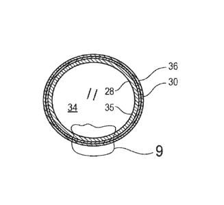
Some embodiments of a silica shell 24 for multi-mode imaging may include a
shell
body 26 having a first inner layer 28 which is formed from silica and a second
layer 30 which
is formed from silica, which is disposed on an outside surface 32 of the first
inner layer 28,
and which includes an imaging material 29 configured for producing an imaging
signal
which is distinct from surrounding tissue. The silica shell 24 also includes a
hollow void 34
disposed within an inner surface of the first inner layer. For some
embodiments, the silica
shell 24 may also include a hydrophobic polymer coating 36 disposed on an
outer surface 38
of the second layer 30. Embodiments of suitable imaging materials 29 may
include a wide
variety of materials suitable for specifically generating a distinct return
signal for a variety of
corresponding imaging modalities including direct visual observation,
ultrasound imaging,
fluoroscopy, MRI and the like.
These small silica shell embodiments 24 which may have a spherical
configuration in
some cases may be useful for multi-mode imaging indications that utilize
direct visual
observation, ultrasound imaging, or both of these modalities. Some composite
gel marker
embodiments 40 (discussed below) may include hollow silica shells 24 that have
a distinct
signal on Doppler ultrasound imaging. In some cases, tumors injected with such
silica shells
24 have been excised with significantly less marker migration relative to
traditional wire
localization. Some such silica shell embodiments 24 may be identified
intraoperatively with
color Doppler ultrasound imaging and B-mode ultrasound imaging in an
intraoperative
setting.
Under B-mode ultrasound imaging, some composite gel marker embodiments
discussed herein may appear similar to other commercially available ultrasound
markers.
However, in some cases, under Doppler mode, some of the composite gel marker
embodiments that include hollow silica shells 24 and discussed herein may
generate a robust,
.. highly-colored signal. Composite gel marker embodiments 40 discussed herein
that are
visible under standard B-mode ultrasound may appear with an imaging signature
that is
similar to the imaging signature or reflected signal of previously available
imaging markers,
however, these same composite gel markers 40 that include hollow silica shell
embodiments
24 and the like may also emit a colorful signal under Doppler ultrasound allow
for rapid
identification with any standard ultrasound machine. Furthermore, some
composite gel
marker embodiments 40 discussed herein may be visible at any depth that can be
imaged
11
CA 03058898 2019-10-02
WO 2018/187594 PCT/US2018/026291
with ultrasound. Some gel marker embodiments 40 discussed herein may also
appear on a
surface of the lung as a blue-gray mark that may be distinct in appearance
from surrounding
lung tissue to further facilitate location of such composite gel markers 40.
Some embodiments of a method of manufacturing a silica shell for multi-mode
imaging may include forming a first inner layer 28 from silica over a template
42, removing
the template 42 by calcination and applying a second layer of silica 30 which
is mixed with
an imaging material 29 onto an outer surface 32 of the first layer 28. Such
method
embodiments my further include applying a hydrophobic polymer coating 36 onto
an outer
surface 38 of the second layer 30. FIG. 3 shows a polystyrene bead that may
serve as a
template 42 for formation of silica shell embodiments 24. In some cases, the
polystyrene
bead 42 may have a spherical configuration and a diameter of about 1.8 microns
to about 2.2
microns which may produce a silica shell 24 having an outer transverse
dimension, in some
cases an outer diameter, of about 1.8 microns to about 2.2 microns. However,
embodiments
with different shapes and other sizes may be suitable in some cases. For
example, such silica
shells 24 having diameters of about 50 nm, 100 nm, 200 nm, 350 nm as well as
other sizes
including larger sizes have been shown to produce a strongly reflective and
distinct
ultrasound signature and return signal that is distinct from surrounding
tissue and may be
used for any of the marker embodiments, including composite gel marker
embodiments 40,
discussed herein. Some such silica shell embodiments 24 which are useful for
ultrasound
imaging and use in composite gel markers 40 or the like may have an outer
transverse
dimension or diameter of about 50 nm to about 20 microns, more specifically,
about 100 nm
to about 2.2 microns, and even more specifically, about 200 nm to about 1.8
microns.
For some embodiments the polystyrene bead 42 may be made by Polyscience Co.
Part No. 19814-15. In general, a method for making hollow silica shells 24 as
shown in the
flow chart 44 of FIG. 10 may include combining a plurality of the polystyrene
template beads
42 with a mixing solvent such as 95% ethanol, adding tetramethoxysilane (TMOS)
to the
solvent, mixing the components under high shear for an extended time, such as
about 4-6
hour in some cases, to produce silica particles which are adhered to the
polystyrene templates
42 as shown in FIG. 5.
A calcination process is then performed at temperatures of about 530 C to
about
570 C for about 5 hours in order to remove the polystyrene templates 42 from
the center of
12
CA 03058898 2019-10-02
WO 2018/187594 PCT/US2018/026291
the silica shells 24 to form hollow silica spheres as shown in FIG. 6. These
newly formed
hollow silica shells which include the first layer 28 only at this stage may
then be treated as a
first inner layer 28 and processed a second time by combining the hollow
silica shells 28 with
more TMOS, a mixing solvent and an imaging material 29 for direct visual
observation such
as a visual dye, more specifically such as methylene blue, into a container
and again mixing
under high shear conditions in order to plate or otherwise add a second layer
30 of silica
particles to the pre-existing silica shell 28 first inner layer, the second
layer 30 being infused
with the imaging material 29 including methylene blue. In some cases, during
the second
mixing process, the methylene blue may also become infused into the
interstices of the first
or inner layer 28 of silica particles forming the predicate silica shell as
shown in FIG. 7. In
some cases the methylene blue is added during a second layer plating process
because the
methylene blue cannot easily withstand the temperatures of the calcination
process used to
remove the template 42 from the inner void 34 of the first layer 28.
The dyed silica shells 24 may then be dried to drive off any remaining mixing
solvent. The dried silica shells 24 are now multi-layer, hollow and the shell
material, or
portions thereof, infused in methylene blue giving them a distinct blue color
which is visible
to the naked eye when placed against materials having colors similar to tissue
colors typically
encountered during a surgical procedure. Thereafter, the silica shells 24 may
be coated with
the optional hydrophobic polymer coating 36 or any other suitable coating in
order to seal the
hollow cavity 34 within each silica shell 24 and prevent ingress of fluids
such as bodily fluids
and the like. Other suitable coatings or configurations that may be used in
order to maintain
the hollow character of the silica shells 24 when deployed in an in vivo
environment may
include painting, powder coating, dispersion coating in addition to
compounding such hollow
silica shells 24 into injection molding or extrusion processes. Such an
embodiment of a
coated silica shell 24 is shown in FIGS. 8 and 9. In some cases, the silica
shells 24 may be
coated using a polymer such as octyltriethoxysilane dissolved in a solvent
such as ethanol.
The silica shells 24 in this configuration may thus serve as multi-mode
imaging
markers by providing a distinct visual signal that can be recognized by the
naked eye of a
human operator (or visual imaging system of a robotic device) as well as
providing a strong
ultrasound imaging signature for ultrasound imaging including color Doppler
imaging. FIG.
11 shows a flowchart 46 that outlines a similar procedure for making silica
shells 24 and
13
CA 03058898 2019-10-02
WO 2018/187594 PCT/US2018/026291
includes more detail regarding the specific parameters of certain process
embodiments. In
some cases, it may be possible to further include or substitute other imaging
materials 29 into
the first layer 28, the second layer 30 or both layers of silica shells 24,
their respective
interior volumes 34 or outer surfaces 32.38 thereof. For example, imaging
materials 29 such
as radiopaque materials may be included in the first layer 28 or the second
layer 30 of such
silica shells 24 to provide an imaging signature under fluoroscopy and the
like. MRI imaging
materials 29, such as any of those MRI imaging materials discussed herein, may
also be so
included in the first layer 28 or the second layer 30 of such silica shells 24
to provide an MRI
image signature under MR' imaging. It should also be noted that although the
silica shell
embodiments 24 discussed herein are generally described as being made from
silica, the
same functionalities and uses discussed herein may be achieved with similar
structures that
are not made primarily of silica and that vary from a spherical shape but do
retain a hollow
configuration.
In some cases, for the processes above for making the silica shells 24, it may
be
desirable to maintain a certain amount of the optional hydrophobic coating on
the outer
surface 38 of each silica shell 24 in order to ensure the integrity and
imaging quality of the
silica shells 24, particularly with regard to the color Doppler ultrasound
imaging quality of
the shells in some cases. Therefore, in some cases, it may be desirable to
avoid rinsing the
silica shells 24 in a solvent that might dissolve the hydrophobic coating 36
once the optional
hydrophobic coating 36 has been applied. For some embodiments, it may be
desirable for the
finished and dried silica shells 24 to have an optional hydrophobic polymer
coating 36 that is
about 0.1 percent to about 5.0 percent by weight of the total weight of the
silica shells 24
disposed on an outer surface 38 of the second layer 30 of the silica shells
24. In some other
cases, the optional hydrophobic coating 36 may not be necessary in order to
maintain the
integrity imaging quality of the silica shells 24 including for color Doppler
ultrasound
imaging. In such cases, it may only be desirable to maintain the hollow
character of the
silica shells 24 by preventing liquid ingress into the interior volume of the
silica shells 24. In
some cases, an outer hydrophobic polymer coating 36 may be made from
octyltriethoxysilane or the like as discussed above.
Some exemplary hollow silica shell embodiments 24, including silica shells
having an
outer diameter of about 1.8 microns to about 2.2 microns, more specifically,
about 2 microns,
14
CA 03058898 2019-10-02
WO 2018/187594 PCT/US2018/026291
may be manufactured by mixing about 18 microliters ( 1 mg) of (3-
trimethoxysilypropyl)
diethylenetriamine (DETA) with about 40 ml ( 2%) of 100% ethanol alcohol.
About 60 ml
of polystyrene template beads 42 having an outer diameter of about 2 microns
and about 400
g ( 1%) of 95% ethanol alcohol may also be added to the DETA/alcohol mixture
in a one
liter depyrogenated FEP container and stirred at about 3,500 rpm for about an
hour. In
general, all of the containers used for the following procedures would be
depyrogenated in
order to maintain a purity of the components being processed and many or all
of the
following procedures would be carried out in a controlled environment area.
Thereafter,
about 3.3 ml (3.4534 g 2%) of tetramethoxysilane (TMOS) may be added to the
alcohol,
DETA and polystyrene template bead 42 mixture and stirring continued for about
4 more
hours in order to plate a first inner layer 28 of silica on an outer surface
of the polystyrene
template beads 42.
The stirred TMOS material may then be transferred into sterile test tubes and
centrifuged at about 3,000 rpm for about 30 minutes, after which time the
fluid from the
.. centrifuged TMOS mixture may be removed with a sterile syringe or the like
and then
discarded. The particles which remain in the test tubes may then be rinsed
with about 50 ml
of 95% ethanol alcohol in each test tube and centrifuged again at about 3,000
rpm for about
30 minutes. This rinsing step may then be repeated two times. It may also be
desirable in
some cases to transfer the particles from one test tube into another test tube
in order to
consolidate the particles and reduce the number of test tubes being used after
each of the
rinse cycles.
The particles may then be transferred to one or more crucibles, such as two 20
ml to
ml crucibles, and allowed to air dry overnight under a laminar flow hood or
the like. The
crucibles containing the particles may then be transferred into an oven and
the temperature in
25 .. the oven ramped up at about 2 degrees centigrade per minute to a
temperature of about 550
degrees centigrade. The particles in the crucible may thereafter be maintained
at the
temperature of about 550 degrees centigrade for about 5 hours in order to
calcinate the
particle structure and remove the polystyrene template bead 42 from the
interior cavity 34 of
the particles leaving a hollow silica shell structure 28. The silica shells 28
may thereafter be
30 allowed to cool and then be broken apart from each other with a
depyrogenated steel spatula
or the like.
CA 03058898 2019-10-02
WO 2018/187594 PCT/US2018/026291
For a second layer of material 30 to be plated to the calcinated hollow silica
shells 28,
about 6 g of methylene blue 29 may be mixed at about 6,000 rpm for about one
hour with
about 500 ml (400 g 1%) of 95% ethanol alcohol and then filtered. This
methylene blue
mixture may then be transferred to 50 ml test tubes and centrifuged for about
ten minutes at
about 3.000 rpm. Once again. about 18 microliters of DETA may be mixed with
about 40 ml
(31.3 g 2%) of 95% ethanol alcohol in a 50 ml test tube which may in turn be
added to the
alcohol and methylene blue mixture of the previous step in an FEP container.
The calcinated
hollow silica shells 28 may also be added to this alcohol, DETA and methylene
blue mixture
and the entire mixture may then be stirred at about 3,500 rpm for about 1
hour. At about 1
hour, about 3.3 ml (3.4534 g 2%) of TMOS may be added and stirring continued
for about
3.5 more hours to allow for dying and shell plating onto the originally
produced silica shells
28.
Once again, this material may then be transferred into 50 ml test tubes and
centrifuged at about 3,000 rpm for about 30 minutes, after which time the
fluid from the
centrifuged TMOS and methylene blue mixture may be removed with a sterile
syringe and
then discarded. The silica shells 24 which remain in the test tubes may then
be rinsed with
about 20 ml to about 30 ml of 95% ethanol alcohol and centrifuged again at
about 3,000 rpm
for about 30 minutes. This rinsing step may then be repeated two more times
reducing the
number of test tubes after each rinse in order to consolidate the silica
shells 24 and reduce the
number of test tubes as discussed above. The shells may then be transferred to
one or more
crucibles and allowed to air dry overnight under a laminar flow hood or the
like.
A hydrophobic outer layer solution may then be prepared by mixing about 100
microliters (90 mg 2%) of octyltriethoxysilane with about 10 ml (7.6957 g
2%) of 100%
ethanol alcohol in a vortex mixer for about 30 seconds. The two-layer hollow
silica shells 24
may then be added to this mixture and mixed with a spatula or the like in
order to create a
homogeneous suspension. The silica shells 24 may be soaked in this mixture and
allowed to
dry overnight in order to apply a hydrophobic outer layer 36 to the silica
shells 24. The silica
shells 24 may then be transferred to a 50 ml test tube and rinsed one time in
95% ethanol
alcohol and centrifuged at about 3,000 rpm for about 30 minutes and thereafter
discarding the
fluid. This rinsing, centrifuging and discarding of the rinsing fluid step may
be repeated two
16
CA 03058898 2019-10-02
WO 2018/187594 PCT/US2018/026291
more times. The thrice rinsed two-layer hollow silica shells 24 may then be
transferred to
one or more crucibles and allowed to air dry overnight under a laminar flow
hood or the like.
The dried silica shells 24 may then again be rinsed in 95% ethanol alcohol and
centrifuged again and allowed to dry overnight again. The crucibles and silica
shells
disposed therein may then be heated in a stable oven at about 60 degrees
centigrade for about
two hours. The resulting two-layer hollow silica shells 24 may then be
measured and
observed in order to verify the production process and quality of the silica
shells 24. In some
cases, the polystyrene template beads 42 used for such a process may include
part number
19814-15 manufactured by the Polysciences Company, the DETA may include part
number
SI18398.0 manufactured by the Gelest Company, the TMOS may include part number
T2033 manufactured by the Spectrum Company, the octyltriethoxysilane may
include part
number 01472 manufactured by the Spectrum Company and the methylene blue may
include
part number J60823 manufactured by the Alfa Aesar Company.
In some cases, the two-layer hollow silica shells 24 produced by the plating
process
discussed above may be further processed into a composite gel marker 40 as
generally shown
in FIGS. 12-15 for use in testing of the silica shells 24, testing of the
composite gel marker
40 or clinical use in marking a site associated with a patient's body 12. In
some cases, a
functionality test sample may be manufactured by combining the hollow silica
shells 24
manufactured by the process above with a gel material 48 such as chitosan, and
more
specifically, processed chitosan 70/2000. For such a sample, a mixture of
about 2 mg of
hollow silica two-layer shells 24 to about 1 ml of chitosan 48 may be injected
into several
silicone tubes 50 having an inner lumen diameter of about 2.3 mm to about 2.5
mm. The
tubes 50 may then be frozen and subsequently freeze dried with a sodium
hydroxide solution
including about 25 ml of sodium hydroxide mixed with about 100 ml of distilled
water. Such
freeze dried gel marker embodiments 40 may then be removed from the silicone
tubes 50 and
used for testing, clinical use, or any other suitable purpose. In some cases,
such gel marker
embodiments 40 may be able to hydrate rapidly, achieving full hydration when
disposed
within an aqueous environment within 24 hours in some cases. Such gel marker
embodiments 40 may be sized and configured to fit into a 20 gauge syringe
applicator device
with sufficient interference for an accurate and timely deployment. Such gel
marker
17
embodiments 40 may also be configured to serve as an external acutely visible
lung tissue
marker with minimal migration in tissue, be visible using color Doppler
ultrasound imaging
systems 24 hours or more after injection and maintain ultrasound visibility
for about 2 weeks
or more.
Various embodiments of silica shells which may include silica nanospheres and
silica
microspheres are discussed herein. Further details regarding the manufacture
and properties
of various nanosphere and microsphere embodiments are discussed in PCT
Publication No.
WO 2009/023697, filed August 13, 2008, by The Regents of the University of
California,
titled "Hollow Silica Nanospheres and Methods of Making Same, published
February 19,
2009, and PCT Publication No. W02014/052911, filed September 27, 2013, by The
Regents
of the University of California, titled "Degradable Silica Nanoshells for
Ultrasonic
Imaging/Therapy", published April 3, 2014, and PCT Publication No. WO
2016/149711,
filed March 21, 2016, by The Regents of the University of California, titled
"Silica
Nanostructures, "Large-Scale Fabrication Methods, and Applications Thereof',
published
September 22, 2016.
Once these silica shell embodiments 24 discussed above have been made, they
are
functional as multi-mode imaging markers 13 and may be used for imaging in a
variety of
conditions and in a variety of configurations. The silica shell embodiments 24
discussed
herein by themselves may be useful for a wide variety of indications that
involve observation
and/or measurement of internal bodily processes and the distribution of
certain tissue or fluid
types within a patient's body 12. For example, silica shells 24 which are
capable of being
imaged with color flow Doppler ultrasound may be introduced into a patient's
body 12 by
direct deployment into tissue, systemic injection into the bloodstream, lymph
system etc. or
any other suitable method. The dispersion of the two-layer silica shells 24
may then be
observed, for example, by color flow Doppler imaging. In some cases, it has
been discovered
that it may be possible to measure a concentration of silica shell embodiments
24 within a
volume of tissue or fluid within a patient's body 12 by perfouning a pixel
count analysis of
the image data produced by the color Doppler imaging. As such, once such
silica shells 24
have been introduced into the patient's body 12, a desired location within the
patient's body
12 may be imaged using color flow Doppler ultrasound. A pixel count analysis
may then be
perfottned on the image data collected by the color Doppler ultrasound process
and a
18
Date Recue/Date Received 2021-10-01
CA 03058898 2019-10-02
WO 2018/187594 PCT/US2018/026291
concentration level of the silica shells 24 determined for a given volume of
the tissue or fluid
imaged. Such a method may be used to image a tumor within the tissue of a
patient and
measure a concentration of silica shells 24 that have been absorbed by the
tumor as well as
locating the position of the tumor or other type of tissue lesion.
Notwithstanding the foregoing discussion of the use of free-standing silica
shells 24
for imaging purposes within a patient's body 12, in order for the silica shell
embodiments 24
to maintain a stable position and provide a desired functionality and
longevity after
deployment into tissue of interest in a patient, it may be desirable to
encapsulate a desired
number of the silica shell embodiments 24 into a composite gel marker 40. As
discussed
above, such a composite gel marker 40 may include a gel material 48, a desired
concentration
of silica shells 24 bound by the gel material 48, as well as any other
components that may
also be bound by the gel material 48. For example, radiopaque imaging
materials 29 or
separate radiopaque markers 52, as shown in FIGS. 12 and 13, may be included
in the
composite gel marker 40 in order to facilitate imaging under x-ray based
imaging methods
such as fluoroscopy, CT and the like. Examples of such radiopaque imaging
materials 29
and markers 52 may include gold, platinum, tantalum, bismuth, barium and the
like. In some
cases, the use of barium sulfate is contemplated for radiopacity wherein low
amounts of
barium sulfate may be useful for imaging with CT, fluoroscopy and the like. In
some
instances, barium sulfate mixed with gelatin material 48 in a ratio of at
least about 1 percent
barium sulfate to gel material 48 by weight has been found to be imageable by
mammography. For such embodiments, barium sulfate powder having a particle
size of
about 2 microns to about 5 microns may be useful. Imaging materials suitable
for MRI use
such as gadolinium including compounds such as gadolinium DTPA, ferrous
gluconate,
ferrous sulfate and the like may be included in the composite gel marker
embodiments 40 in
order to facilitate the MRI imaging modality.
Some embodiments of a multi-mode composite gel marker 40 for ultrasound
imaging
may include a plurality of silica shells 24, each silica shell 24 including a
shell body 26
having a layer 28 which is formed from silica and a hollow void 34 disposed
within the inner
surface 35 of the silica layer 28 as shown in the silica shell embodiment 24
of FIG. 6. The
composite gel marker 40 may also include an imaging material 29 which is
configured to
produce an imaging signal that is distinct from surrounding tissue and a
hydroscopic gel
19
CA 03058898 2019-10-02
WO 2018/187594 PCT/US2018/026291
material 48 which is disposed about the plurality of silica shells 24 and
imaging material 29
so as to form an expandable composite gel marker body 54. For some embodiments
of such
a multi-mode composite gel marker 40, the plurality of silica shells 24 may
include a shell
body 26 having a first inner layer 28 which is formed from silica and a second
layer 30 which
is formed from silica, which is disposed on an outside surface 32 of the first
inner layer 28.
and which includes the imaging material 29 configured for producing an imaging
signal
which is distinct from surrounding tissue such as the silica shell embodiment
24 shown in
FIG. 7. The silica shells 24 also include a hollow void 34 disposed within the
inner surface
35 of the first inner layer 28. In some cases, a hydrophobic polymer coating
36 may be
disposed on an outer surface 38 of the second layer 30 of the plurality of
silica shells 24 as
shown in FIG. 8.
Visually distinct imaging materials 29 including dyes such as methylene blue
and the
like may also be included in the gel material 48 of a composite gel marker 40
in order to
make such a composite gel marker body 54 visually distinct from surrounding
tissue once
deployed to facilitate direct visual observation of such a gel marker
embodiment 40. Any
suitable or desirable combination of imaging materials 29 for imaging
enhancement may be
included in the shell structure of the silica shell embodiments 24 or in the
gel material 48 of
the composite gel marker embodiments 40 discussed herein that include such
silica shells 24
in order to achieve the desired multi-mode imaging marker properties of
various composite
gel marker embodiments 40. For example, any of the imaging materials 29 such
as
radiopaque materials, MRI materials, visually distinct materials such as dyes
may be
included in either the structure of the silica shell embodiments 24 or
encapsulated within or
otherwise secured to the gel material 48 of composite gel marker embodiments
40 separately
from the silica shell structures 24. Different types of silica shells 24 may
also be included in
particular composite gel marker embodiments 40. For example, some composite
gel marker
embodiments 40 may include silica shells 24 of varying diameter, wall
thickness, coating
thickness, imaging function and the like in order to provide a desired
variation in longevity,
function, time release function or any other desirable function. Furthermore,
some composite
gel marker embodiments 40 may include a variety of silica shells that have
different imaging
materials. For example, some embodiments of a single composite gel marker may
include a
plurality of silica shells 24 having a radiopaque imaging material 29 in the
outer layer 30,
CA 03058898 2019-10-02
WO 2018/187594 PCT/US2018/026291
additional silica shells having an MRI imaging material 29 in the outer layer
30, and still
further additional silica shells 24 having a visually distinct imaging
material 29. such as a dye
like methylene blue, in the outer layer 30. As such, each type of silica shell
24 having a
different imaging material 29 may serve a different imaging function within
the same
composite gel marker embodiment 40. Some embodiments of composite gel marker
bodies
54 of such multi-mode composite gel markers 40 may include ratios of about 0.1
mg/ml to
about 8.0 mg/ml of silica shell embodiments 24 to volume of gel material 48.
FIG. 12 shows a molding process whereby a plurality of silica shells 24 are
being
bound together and encapsulated by the gel material 48 with a single gamma
shaped
radiopaque ribbon marker 52 by a gel material 48 that is molded into an inner
cylindrical
cavity of a silicone tube 50. The resulting multi-mode composite gel marker 40
may then be
pushed out of the inner cylindrical cavity and further processed by
compressing the
composite gel marker body 54 in order to reduce the volume and outer profile
such that the
composite gel marker 40 may then be loaded into a distal portion of an inner
lumen of a
cannula of an applicator, such as the applicator shown in FIGS. 16-24. The
composite gel
marker embodiment 40 may also be compressed and in some cases de-aired after
being
freeze dried while still disposed within an inner lumen of a silicone tube 50.
In general,
some such composite gel marker embodiments 40 may have an unexpanded dry
length of
about 2 mm to about 40 mm and an unexpanded dry transverse outer dimension of
about 0.5
mm to about 2 mm. In some cases. such composite gel markers 40 may include gel
materials
48 having properties specific to biocompatibility, duration or longevity in an
in vivo
implanted circumstance, expansion ratio when exposed to aqueous fluids,
expansion rate
when exposed to aqueous fluids and the like.
In some cases, multi-mode composite gel markers 40 may be constructed
according
generally to the process steps of the flowchart 55 shown in FIG. 15 wherein
dry gel material
48 is combined with distilled water and any suitable silica shell embodiments
24 including
any of those discussed herein. For some embodiments, the composition by weight
of gel
material 48, silica shells 24 and distilled water may be about 88% gel
material 48, about 3%
silica shells 24 and less than about 10% water. The gel-water-silica shell
mixture may then
be dispensed into an inner cylindrical cavity of a tubular mold made from a
soft elastic
material, such as the tubular silicone mold 50 shown in FIG. 12. A ribbon
radiopaque
21
CA 03058898 2019-10-02
WO 2018/187594 PCT/US2018/026291
marker embodiment 52 may also be included in the mixture dispensed into the
cavity. The
molded composite gel marker 40 may then be frozen and subsequently freeze
dried.
Once freeze dried, the composite gel marker 40 may be pushed out of the
cylindrical
cavity of the silicone tubing 50 and compressed in order to remove air and
reduce the
transverse dimension and area so that the composite gel marker 40 will fit
within the inner
lumen of the distal portion of the cannula of the applicator as shown in FIG.
24A. For some
embodiments, the freeze dried composite gel markers 40 may be compressed by
rolling them
between two silicone sheet surfaces (not shown) to remove air pockets and
reduce profile.
For some composite gel marker embodiments 40, gel materials 48, and
particularly,
hydrophilic gel materials 48 such as chitosan gel, porcine gel, collagen,
methyl cellulose,
polyethylene glycol (PEG), suitable polysaccharides, suitable hydrogels and
the like may be
used. It may also be desirable in some cases to adjust the formulation of the
gel material 48
of the composite gel markers 40 in order to adjust the expansion time,
duration of physical
integrity of the composite gel marker 40 within the body 12 of a patient as
well as other
attributes. For some embodiments, the radiopaque ribbon marker 52 may be made
from an
elongate element of metallic radiopaque material such as gold, platinum,
tantalum and the
like.
In some cases, gelatin materials 48 may be manufactured using a variety of
formulations in order to achieve desired properties of the finished material.
For example, a
gelatin material 48, such as Gelita MadeIla Pro 100, may be mixed with
distilled water in a
variety of ratios in order to tailor the resulting gelatin material properties
to a particular
indication or use. Such a gelatin material 48 may be mixed in ratios such as
about 4 g of
gelatin material to about 100 ml of distilled water, about 4.5 g gelatin
material to about 100
ml of distilled water. or 5.0 g of gelatin material to about 100 ml of
distilled water. Gelatin
formulations mixed at these various ratios may then dispensed into an inner
lumen of a
silicone tube 50 having a length of about 3 cm and a transverse inner
dimension of the inner
lumen of about 2 mm, about 2.4 mm or any other suitable inner transverse
dimension. After
injection into the inner lumen, the gelatin formulations 48 and silicone
tubing 50 disposed
about the gelatin material 48 may then be frozen. Thereafter, the gelatin
material 48
disposed inside the silicone tubing 50 may be freeze dried. After freeze
drying, the gelatin
22
CA 03058898 2019-10-02
WO 2018/187594 PCT/US2018/026291
material 48 may be rolled under pressure so as to remove air from the gelatin
material 48 and
reduce the overall volume of the gelatin material 48.
For gelatin materials 48 subjected to these processes, an outer transverse
dimension
of gelatin molded in 2 mm silicone tubes may be about 0.025 inches to about
0.031 inches,
more specifically, about 0.026 inches to about 0.030 inches, and even more
specifically,
about 0.027 inches to about 0.028 inches. These rolled gelatin pads may also
have a dry
weight of about 7 mg to about 7.8 mg and in some cases, an axial length of
about 22 mm to
about 24 mm. Upon soaking such gelatin pads in water, the gelatin pads may
expand to an
outer transverse dimension of about 1.5 mm with an axial length of about 23 mm
to about 25
mm in some cases. For gelatin materials subjected to these processes, an outer
transverse
dimension of gelatin molded in 2.4 mm silicone tubes may be about 0.026 inches
to about
0.034 inches, more specifically, about 0.029 inches to about 0.033 inches, and
even more
specifically, about 0.031 inches to about 0.032 inches after being freeze
dried and
subsequently compressed. These rolled gelatin pads may have a dry weight of
about 6.2 mg
to about 8 mg.
Some embodiments of an applicator 56 for delivering a multi-mode composite gel
marker 40 to a target site such as a tumor location, lesion location, area of
interest location or
the like within subdermal tissue of a patient 12 may include a handle 58
having an interior
cavity 60, a slide bore 62 and a retraction slot 64. The applicator 56 may
also include a
cannula 66 having an inner lumen 68 extending a length thereof and a
positioning rod 70
which is disposed within the inner lumen 68 of the cannula 66 and which has a
proximal end
72 secured to the handle 58. The applicator embodiment 56 may also have a
retraction
shuttle 74 which is secured to a proximal end 76 of the cannula 66, which
includes an inner
lumen 78 that is coaxial with the inner lumen 68 of the cannula 66 and which
slides within
the slide bore 62 of the handle 58 thereby imparting relative axial
displacement between the
cannula 66 and the positioning rod 70. The applicator 56 may also include a
retraction knob
80 which is secured to the retraction shuttle 74 and which is disposed within
the retraction
slot 64 of the handle 58 in a distal axial position such that the retraction
slot 64 mechanically
limits the axial movement of the retraction knob 80 and cannula 66 between the
distal axial
.. position (shown in FIGS. 16 and 23A) with a distal end 82 of the cannula 66
extending
23
CA 03058898 2019-10-02
WO 2018/187594 PCT/US2018/026291
distally beyond a distal end 84 of the positioning rod 70 and a proximal axial
position (shown
in FIG. 23C) with the distal end 82 of the cannula 66 being disposed proximal
of the distal
end 84 of the positioning rod 70.
A composite gel marker 40 in an unexpanded state may be disposed in a cavity
formed within the inner lumen 68 of the cannula 66 between the distal end 82
of the cannula
66 and the distal end 84 of the positioning rod 70 with the retraction knob 80
and cannula 66
in the distal axial position. The composite gel marker 40 so disposed may
include any of the
composite gel marker embodiments 40 discussed herein. In some cases, it may be
desirable
to include an optional plug 85 within the inner lumen 68 of the cannula 66
that detachably
secures the composite gel marker 40 to the inner lumen 68 of the cannula 66 in
order to
prevent the composite gel marker 40 disposed within the inner lumen 68 from
accidentally
falling out of the inner lumen 68 prior to deployment. An example of such a
plug 85 is
shown in FIG. 24A. Plug embodiments 85 may be formed as part of the composite
gel
marker body 54 (such as at a first or distal end 120 thereof discussed below)
or may be
formed separately between an inner surface of the inner lumen 68 of the
cannula 66 and an
outer surface of the composite gel marker 40. For some embodiments, plug 85
may be made
from a gel material 48 such as PEG or the like. The plug 85 may be configured
to break
away and release the composite gel marker 40 upon actuation of the retraction
knob 80 as the
distal end 82 of the cannula 66 is proximally retracted relative to the
composite gel marker 40
and positioning rod 70.
In some instances, the applicator 56 may also include an interlock 86 which
has a first
tab 88 secured to and extending inwardly from an inner surface of the interior
cavity 60 of
the handle 58 and a second tab 90 extending outwardly from the retraction
shuttle 74. The
second tab 90 may be in an overlapped configuration with respect to the first
tab 88 along a
direction substantially parallel to a longitudinal axis 92 of the positioning
rod 70 and cannula
66 such that proximal retraction of the retraction knob 74 while in the distal
axial position is
mechanically prevented by the overlapped configuration of the first tab 88 and
second tab 90
(as shown in FIGS. 20 and 21) until the retraction knob 80 is depressed by a
downward force
F so as to eliminate the overlap between the first tab 88 and second tab 90
(as shown in FIG.
22). For some embodiments, such applicators 56 may also have a removable
interlock 94
including a removable block 96 having a snap fit into the retraction slot 64
proximal of the
24
CA 03058898 2019-10-02
WO 2018/187594 PCT/US2018/026291
retraction knob 80 when the retraction knob 80 is in the distal axial
position. This
configuration serves to mechanically prevent proximal retraction of the
retraction knob 80
until the removable interlock 94 is manually removed from the retraction slot
64. A Luer
fitting 98 having an inner lumen is disposed on and secured to a distal end
100 of the
retraction shuttle 74 with the inner lumen of the Luer fitting 98 being in
fluid communication
and coaxial with the inner lumen 68 of the cannula 66. A shield 102 which is
removable and
which has a rigid tubular body is disposed over the cannula 66 and is secured
to the Luer
fitting 98 of the retraction shuttle 74 with a corresponding Luer fitting 104
secured to a
proximal end of the rigid tubular body of the shield 102. The shield 102 is
used to protect the
cannula 66 during storage and shipment of the applicator 56 prior to use.
Some applicator embodiments 56 for use in deploying composite gel markers 40
including such freeze dried gel pads may be configured to fit smoothly into an
inner lumen of
currently available 19 gauge introducer devices 106 (as shown in FIGS. 28-30),
include a
luer lock fitting 98 that is compatible with currently available 19 gauge
introducer devices
106, and include 0.5 cm spaced depth insertion markings 108 on a shaft
thereof. It may also
be useful for such applicator embodiments 56 to have a smooth and low force
actuation/deployment mechanism, to be light weight and suitable for single-
handed
deployment of composite gel markers 40, and include a mechanism for preventing
inadvertent deployment of composite gel markers therefrom, such as the
interlock 86 and
removable interlock 94, discussed above. Such an applicator 56 for the
deployment of
composite gel marker may be suitable for marking tumors within tissue of a
patient's body
12 within 1 cm of a target location and mark lung tumors within 3 cm of the
tumor location.
As discussed above. FIGS. 16-24C illustrate an embodiment of an applicator 56
that
may be used to deploy one or more markers such as the composite gel marker
embodiments
40 shown in FIGS. 12 and 13. As discussed above, some applicator embodiments
56 include
a handle 58, a cannula 66 that is configured to advance into tissue, and a
positioning rod 70
that is disposed in fixed relation with the handle 58. A retraction knob 80 is
slidingly
disposed relative to the handle 58 in an axial direction and is secured to the
retraction shuttle
74 which is in turn secured to a proximal end 76 of the cannula 66 such that
the retraction
knob 80 and proximal end 76 of the cannula 66 may be axially displaced over a
limited range
of axial motion defined by the retraction slot 64 in the handle 58 in which
the retraction knob
CA 03058898 2019-10-02
WO 2018/187594
PCT/US2018/026291
80 is captured. For such an arrangement, with the retraction knob 80 and
cannula 66 slid
distally forward relative to the positioning rod 70, there is an axial gap in
the inner lumen 68
of the cannula 66 between the distal end 84 of the positioning rod 70 and
distal end 82 of the
cannula 66 that has a length and transverse dimension sufficient to
accommodate an outer
dimension of composite gel marker embodiments 40 disposed therein. When the
retraction
knob 80 and cannula 66 are proximally retracted relative to the handle 58 and
positioning rod
70, one or more of the composite gel markers 40 may be exposed and deployed in
place as
the cannula 66 and positioning rod 70 are proximally withdrawn from the marker
deployment
target site 110 as shown in .......................................... FIG.
25 for example. For this mode of deployment, it may be
desirable for the retraction displacement of the retraction knob 80 and
cannula 66 to be at
least as great as an axial length of the composite gel marker 40 being
deployed. For some
embodiments, the retraction slot 64 and corresponding retraction displacement
length may be
about 1 cm to about 5 cm, more specifically, about 2 cm to about 4 cm. In
addition, the
applicator 56 may be configured to hold two or more composite gel makers 40
and deploy
them sequentially with each retraction of the retraction knob 80. For the
applicator
embodiments 56 discussed above, the cannula 66 and positioning rod 70 may be
from
suitably resilient and high strength materials such as stainless steel. The
handle 58, retraction
shuttle 74, retraction knob 80, Luer fitting 98 as well as other components of
these
assemblies may be made from a suitable substantially rigid polymer such as ABS
plastic,
PVC plastic, or the like. For some embodiments, the cannula 66 may have a
length of about
5 cm to about 20 cm and the corresponding positioning rod 70 sized to extend
slightly
beyond a distal end of the cannula 66 when the cannula is in a proximally
retracted position
as shown in FIG. 23C and 24C. For some embodiments, the inner lumen 68 of the
cannula
66 may have an inner diameter of about 0.5 mm to about 2 mm.
FIG. 22A illustrates an embodiment of an applicator 56' that may have all of
the same
features, dimensions and materials as those of applicator 56 discussed above,
but also
includes and adjustable standoff 105 that is configured to adjustably limit a
depth of
penetration of the distal end 82 of the cannula 66 into the tissue of the
patient 12 as measured
from an outside surface level of the tissue. The standoff 105 has a
substantially planar
.. configuration that lies substantially perpendicular to the longitudinal
axis 92 of the
positioning rod 70. The standoff 105 further includes an aperture 105A through
which the
26
CA 03058898 2019-10-02
WO 2018/187594 PCT/US2018/026291
cannula 66 is slidingly disposed. The standoff 105 is supported by a rigid
standoff shaft 103
that is secured to the standoff 105 at a distal end thereof and to a
ratcheting shuttle 109 at a
proximal end thereof. The ratcheting shuttle 109 is coupled to the handle 58'
such that when
radially depressed, the ratcheting shuttle 109 can be translated in an axial
direction
substantially parallel to the longitudinal axis 92 of the positioning rod 70
so as to
correspondingly translate the standoff 105 in an axial direction relative to
the cannula 66.
The standoff 105 provides sufficient surface area against an outside surface
of a patient's
tissue such the handle 58' may be lightly pushed in the direction of the
tissue surface in order
to fix the position of the handle 58' relative to the position of the tissue
surface. As such, the
axial adjustment of the standoff 105 as carried out by ratcheting axial
adjustment of the
ratcheting shuttle 109 may be used to set a depth of penetration of the
cannula 66 into a
patient's tissue. In some cases, the ratcheting shuttle 109 may be configured
to release the
axial position of the ratcheting shuttle 109 by disengaging associated
ratcheting surfaces of
the respective ratcheting shuttle 109 and handle 58' when the ratcheting
shuttle 109 is
radially depressed against a resilient biasing force. The ratcheting shuttle
109 may then be
temporarily locked in place with regard to axial position of the standoff 105
once the radially
inward force is released and the associated ratcheting surfaces (not shown) re-
engaged. In
some cases, the standoff 105 may have an axial range of adjustment of about 2
cm to about
cm. For some embodiments, the standoff 105 and ratcheting shuttle 109 may be
made
20 from a rigid polymer such as ABS plastic, PVC plastic or the like. The
standoff shaft 103
may be made from a suitable high strength resilient material such as stainless
steel or the
like.
As discussed above, certain imaging modalities are not well suited for imaging
certain types of tissue. The imaging of lung tissue with ultrasound is an
example. The tissue
of the lung is too spongy and porous with a large percentage of air pockets to
be efficiently
imaged with ultrasound imaging equipment in general. However, a need has been
shown for
minimally-invasive, low-cost, and convenient methods of lung tissue and
particularly lung
nodule localization. An ultrasound-visible marker placed well ahead of surgery
could
alleviate many of the issues associated with existing wire localization
techniques for imaging
lung nodules and the like. However, as discussed above, it is traditionally
difficult to image
the lung due with ultrasound to the air within the parenchyma and airways.
Notwithstanding
27
CA 03058898 2019-10-02
WO 2018/187594 PCT/US2018/026291
this difficulty, some silica shell embodiments 24 and associated composite gel
marker
embodiments 40 discussed herein may be used in lung parenchyma to image
pulmonary
tissue using ultrasound imaging.
Certain composite gel marker embodiments 40 that are generally hydrophilic may
be
useful as imaging signal conduits for deployment in tissue that is not
otherwise conducive to
transmission of a particular imaging energy. Some multi-mode composite gel
marker
embodiments 40 may include a strong return signal by an imaging modality such
as
ultrasound imaging, including color flow Doppler ultrasound imaging and the
ability to
function as an ultrasound imaging signal conduit. For such applications, a
composite gel
marker embodiment 40 may be used to mark a lesion in lung tissue of a patient
12 and also
provide an ultrasound imaging signal conduit to the extremities of the
composite gel marker
40 and the lesion 110 disposed about or adjacent to the composite gel marker
40.
Some methods of marking and ultrasound imaging a target site 110 disposed
within
lung tissue of a patient's body may include deploying a composite gel marker
40 at a target
site 110 within lung tissue of the patient with the composite gel marker 40
extending from
the target site 110 to an outer surface level of the patient's lung.
Thereafter, the target site
110 may be imaged with ultrasound from the outer surface level of the
patient's lung through
the composite gel marker, particularly through a composite gel marker
saturated with
aqueous fluids, and to the target site 110 with an ultrasound imaging signal
that travels
through the composite gel marker 40 from the outer surface level to the target
site 110. Such
composite gel markers 40 may require a greater length than similar composite
gel markers 40
not being used as imaging signal conduits. Some such embodiments of multi-mode
composite gel markers 40 may have an axial length of about 1 cm to about 10
cm, more
specifically, about 3 cm to about 8 cm. In some instances, composite gel
marker
embodiments 40 may include gelatin and 2[tm microspheres with a diameter of
about 1.6mm
and a length of about 15mm.
FIGS. 25-34 illustrate an embodiment of a medical procedure wherein a multi-
mode
composite gel marker embodiment 40 is being deployed in lung tissue 114. The
composite
gel marker 40 includes silica shells 24 as discussed above for color Doppler
ultrasound
imaging and visual identification due to the methylene blue component and a
radiopaque
ribbon 52 that is suitable for radiographic imaging such as fluoroscopy. The
composite gel
28
CA 03058898 2019-10-02
WO 2018/187594 PCT/US2018/026291
marker 40 may also include a radiopaque imaging material 29 such as a
radiopaque powder
that is dispersed throughout all or a portion of the composite gel marker body
54. In FIG. 25,
a distal end of a biopsy cannula 112 is disposed above lung tissue 114 of a
patient 12 and a
tumor target site 110 is shown disposed below an outer surface 116 of the lung
tissue 114.
The biopsy cannula 112 is advanced into the lung tissue 114 as shown in FIG.
26 until the
distal end of the biopsy cannula is disposed in the tumor 110. Once the biopsy
cannula 112
has cut boundaries of the biopsy tissue to be sampled, the biopsy cannula 112
and biopsy
sample may then be proximally retracted and removed from the patient's lung
tissue 114.
FIG. 27 shows the lung tissue 114 after removal of a tissue sample from the
tumor 110 due to
retraction of the biopsy cannula and with a channel 118 in the lung tissue 114
and tumor 110
where the biopsy sample was removed.
Thereafter, the cannula 66 of the applicator 56, the distal end 82 of which is
loaded
with a composite gel marker embodiment 40, may be distally advanced through an
inner
lumen of an optional introducer 106 and into the tissue channel 118 left in
the lung tissue 114
from the previous biopsy process. The cannula 66 may be advanced until a first
end 120 of
the composite gel marker 40 is disposed within the channel 118 within the
tumor 110 and a
second end 122 of the composite gel marker 40 is disposed adjacent an outer
surface 116 of
the lung tissue 114 as shown in FIG. 29. The composite gel marker 40 may also
be axially
positioned such that the second end 122 of the composite gel marker 40 extends
outwardly
from the outer surface level 116 of the lung tissue 114 in some cases. For
example, the
second end 122 of the composite gel marker 40 may extend at least about 0.1 cm
to about 1.0
cm from the surface 116 of the lung tissue 114 at the time of deployment in
some instances.
The cannula 66 of the applicator 56 may then be proximally retracted while the
distal end 84
of the positioning rod 70 of the applicator 56 presses against the second end
122 of the
composite gel marker 40 to maintain the axial position of the composite gel
marker 40
relative to a position of the tissue of the target site 110 during the
retraction of the cannula
66. For the applicator embodiment 56 shown in FIGS. 16-24C, the cannula 66 may
be
proximally withdrawn relative to the composite gel marker 40 by translating
the retraction
knob 80 in a proximal direction relative to the handle 58 and positioning rod
70 while
maintaining the axial position of the handle 58 relative to the lung tissue
114. In addition, for
the applicator embodiment 56 shown, prior to actuation of the retraction knob
80, the
29
CA 03058898 2019-10-02
WO 2018/187594 PCT/US2018/026291
retraction knob 80 may first be depressed in an inward radial direction with
force F relative
to the longitudinal axis 92 of the positioning rod 70 in order to disengage
the interlock 86 of
the retraction shuttle 74 and handle 58 as shown in FIGS. 21 and 22. In
addition, for some
embodiments, the removable interlock 94 may be removed from the handle 58 such
that the
removable block 96 of the removable interlock 94 is disengaged from the
retraction slot 64 of
the handle 58 in order to enable proximal retraction of the retraction knob 80
by removing
the mechanical interference of the removable interlock 94 with the retraction
knob 80. Once
the cannula 66 has been proximally retracted and the composite gel marker 40
deployed, the
cannula 66 and positioning rod 70 of the applicator 56 may then be proximally
withdrawn
with the composite gel marker 40 disposed within the tissue channel 118 left
by removal of
the biopsy sample as shown in FIG. 31. The introducer 106 may also be
proximally
withdrawn from the tissue channel 118 at the same time or at any other
suitable time during
the procedure.
In some cases, if a biopsy is not performed prior to deployment of the
composite gel
marker 40, the introducer 106 may be advanced directly through the tissue 114,
typically
with a stylet (not shown) disposed within the inner lumen of the introducer
106. Such a
stylet may extend just beyond a distal end of the introducer 106 and be
configured so as to
provide a pointed tissue penetrating tip for the introducer 106. Once the
introducer is in
place, the stylet may be proximally withdrawn from the inner lumen of the
introducer 106.
.. In some instances, for procedures utilizing an introducer 106, the
introducer 106 may be
positioned such that a distal end 107 of the introducer 106 is disposed about
1 cm to about 2
cm into the lung tissue 114 from the outer surface level 116. Other suitable
positions for the
distal end 107 of the introducer are also contemplated. It should also be
noted that this
procedure may be performed without the use of an introducer 106 or a pre-
existing tissue
.. channel 118. For some deployment embodiments, the cannula 66 of the
applicator 56 may
be advanced directly into lung tissue 114 to the target site under any
suitable imaging
modality such as fluoroscopy, CT, MRI or the like. Once the cannula 66 and the
composite
gel marker 40 disposed in a distal end 82 thereof are properly positioned at
the target site
110, the composite gel marker 40 may then be deployed from the distal end 82
of the cannula
66 at the target site 110 as discussed above.
CA 03058898 2019-10-02
WO 2018/187594 PCT/US2018/026291
Once so deployed, the composite gel marker 40 may begin to expand and absorb
surrounding aqueous body fluids due to a hydrophilic property of the gel
material 48 in some
cases as shown in FIG. 32. Such expansion may be useful in order to fill the
void 118 left by
the biopsied tissue and fix the position of the composite gel marker 40
relative to the
surrounding lung tissue 114. The expanded composite gel marker 40 may also
serve to seal
the tissue channel 118 which may be useful to provide hemostasis at the biopsy
site in some
cases. It should be noted that the gel material 48 and processing may in some
instances be
chosen to adjust the expansion ratio and rate to desired values. In some
cases, the composite
gel marker 40 may have an expansion ratio by volume of about 1:1.5 to about
1:10, more
specifically, about 1:2 to about 1:3.
The biopsy procedure embodiment and deployment procedure embodiment shown in
FIGS. 25-32 may be carried out with the aid of one or more of any suitable
type of imaging
modality, including typically for this procedure visual imaging, fluoroscopic
imaging, CT
imaging, mammography. and MRI. For composite gel marker embodiments 40 that
include
MRI imaging materials 29, such materials may include gadolinium, ferrous
gluconate,
ferrous sulfate, titanium and the like. As discussed above, ultrasound
imaging, including
color Doppler ultrasound imaging, is not typically suitable for lung tissue
indications due to
the physiological properties of lung tissue 114. However, once the elongate
composite gel
marker 40 has been deployed with a second end 122 of the composite gel marker
40 disposed
at or above the surface 116 of the lung tissue 114 and after the composite gel
marker 40 has
absorbed sufficient fluids, an ultrasound imaging signal may then propagate
through the
composite gel marker 40 down to the tumor 110 in the lung tissue 114. This
imaging signal
conduit of the composite gel marker 40 functions to aid the treating physician
with imaging
of the tumor with ultrasound imaging equipment 16 which may be a more suitable
and
convenient imaging modality as compared to other imaging modality options.
In some cases, lung injections for deploying composite gel marker embodiments
40
discussed herein may be performed using a 19-gauge introducer 106 with a 20-
gauge needle.
Such injections may be performed under CT or fluoroscopic guidance to confirm
placement
in the lung 114. Ultrasound imaging may be effectively performed on the
composite gel
marker embodiments 40 about 1 minute to about 10 minutes after injection in
some cases. It
has been shown that for some composite gel marker embodiments 40, ultrasound
imaging
31
CA 03058898 2019-10-02
WO 2018/187594 PCT/US2018/026291
may be performed using color Doppler through the thoracic wall to observe an
implant site at
about 1 minute to about 10 minutes after injection, 7 days after injection, 21
days after
injection or at any other suitable time and still provide a highly visible
ultrasound imaging
signal. The area of composite gel marker placement may be imaged in some cases
with
Doppler ultrasound from the lung surface. Therefore, the composite gel marker
embodiments
40 discussed herein may be placed during an initial pulmonary biopsy or at any
point several
weeks prior to planned surgical excision, facilitating scheduling on the day
of surgery.
Ultrasound imaging may then be used during thoracoscopic surgery or mini-
thoracotomy to
verify nodule location prior to resection.
In addition, certain modifications or imaging options may be used in order to
more
efficiently image the lung tumor 110 using the imaging signal conduit formed
by the
expanded composite gel marker 40. For example, FIG. 32 shows the composite gel
marker
40 and tumor 110 being imaged by an ultrasound system with a transducer window
124 of a
transducer 126 disposed over the second end 122 of the composite gel marker 40
and with an
optional liquid filled inflatable lens 128 disposed between and in contact
with the transducer
window 124 and the second end 122 of the composite gel marker 40. An example
of a visual
display of such imaging of the composite gel marker 40 and target site 110 is
shown in FIG.
33 which shows the screen 129 of an ultrasound imaging system console during
the imaging
process. An imaged representation 127 of the composite gel marker embodiment
40 being
imaged is shown on the display screen 129. Once the tumor 110 has been
identified and
located with ultrasound imaging, the tumor tissue 110 and composite gel marker
40 may be
removed by surgical excision or any other suitable method as shown in FIG. 34.
In some
cases, the excision may be performed under ultrasound imaging guidance using
the
composite gel marker 40 as an imaging conduit up to such point that the
composite gel
marker 40 has also been removed from the lung tissue 114.
Some methods of marking and ultrasound imaging a target site within a
patient's
body may include preparing the applicator 56 for use by removing the shield
102 from the
cannula 66 of the applicator 56 and advancing a distal end 82 of the cannula
66 of an
applicator 56 to a target site 110 within a patient's body 12 below a surface
of the patient's
skin. In some cases, the target site 110 within the patient's body 12 may have
been identified
and located with an imaging modality other than an ultrasound imaging modality
such as
32
CA 03058898 2019-10-02
WO 2018/187594 PCT/US2018/026291
with fluoroscopy or MRI. In addition, in some instances, an introducer 106 may
have been
advanced to a target site 110 and the cannula 66 subsequently advanced through
an inner
lumen of the introducer 106 to the target site 110. In some cases, the
position of the
introducer 106 may be used to guide the axial position of the cannula 66
whereby the
introducer 106 is placed in a position with a distal end thereof adjacent the
target site 110.
The cannula 66 may then be advanced through the inner lumen of the introducer
106 and
secured relative to the introducer 106. For some embodiments, the cannula 66
may be
secured relative to the introducer 106 by coupling respective Luer fittings of
the cannula 66
and introducer 106.
The distal end 82 of the cannula 66 may be advanced such that a multi-mode
composite gel marker 40 disposed within a cavity in an inner lumen 68 of the
cannula 66
between a distal end 82 of the cannula 66 and a distal end 84 of a positioning
rod 70 disposed
within the inner lumen 68 of the cannula 66 is in a desired position relative
to the target site
110. Such methods may also include proximally retracting the retraction knob
80 and the
cannula 66 of the applicator 56 relative to tissue 114 of the target site 110,
the composite gel
marker 40, the positioning rod 70 and a handle 58 of the applicator 56 until
the outer radial
constraint of an inner surface of an inner lumen 68 of the cannula 66 is
removed from the
composite gel marker 40 so as to deploy the composite gel marker 40 at the
target site 110.
Thereafter, the cannula 66 and positioning rod 70 may be withdrawn from the
patient's body
12. The composite gel marker 40 and adjacent target site 110 may subsequently
be imaged
with ultrasound imaging and the target site 110 optionally treated during or
in conjunction
with the ultrasound imaging of the target site 110.
FIGS. 35-38 show a deployment method embodiment for deployment of one or more
multi-mode composite gel markers 40 in breast tissue 130 in order to mark a
target site lesion
110 within the breast tissue 130. A biopsy site and resulting channel 118 in
the tissue of a
tumor and surrounding tissue 130 may be created in the breast tissue 130 by
the same biopsy
methods and devices as those discussed above with regard to imaging and
treatment of lung
tissue 114. Thereafter, the cannula 66 of the applicator 56 loaded with one or
more multi-
mode composite gel markers 40 may be advanced through an inner lumen of an
optional
introducer 106 until the cannula 66 is disposed within a void 118 in a tumor
110 of a patient's
breast tissue 130 with a first end 120 of the composite gel marker 40 disposed
in the fundus
33
CA 03058898 2019-10-02
WO 2018/187594 PCT/US2018/026291
or distal end of the void 118 substantially centered in the tumor 110 and a
second end 122 of
the composite gel marker 40 disposed adjacent an outer boundary 132 of the
tumor 110 as
shown in FIG. 35. After such positioning of the cannula 66, the distal end 82
of the cannula
66 of the applicator 56 may be proximally retracted while the positioning rod
70 of the
applicator 56 presses distally against the second end 122 of the composite gel
marker 40 to
maintain the axial position of the composite gel marker 40 during the
retraction of the
cannula 66 as shown in FIG. 36. Thereafter, the cannula 66, positioning rod 70
and
applicator 56 may be removed with the multi-mode composite gel marker 40
disposed within
the tissue channel left by removal of the biopsy sample in the center of the
tumor as shown in
FIG. 37.
In some circumstances, rather than using such embodiments of the multi-mode
composite gel marker 40 to mark the center of the tissue lesion or tumor 110
as shown in
FIGS. 35-37, two or more composite gel markers 40 may be deployed by the
method of
FIGS. 35-37 in locations disposed at opposite ends of a tumor 110 in breast
tissue 130 or any
other tissue such as lung tissue 114 of a patient 12 in order to mark a
periphery of a tissue
lesion 110 such as a tumor as shown in FIG. 38. In addition, in some cases, it
may be
desirable to use an elongate composite gel marker 40 for such a method with a
second end
122 of the composite gel marker 40 extending to or beyond a surface of the
tissue in order to
serve a dual purpose of marking the center of the tumor 110 as well as
functioning as a
localization "wire" or conduit in that it may be possible for a clinician to
follow the path of
the elongate composite gel marker 40 from the surface of the tissue to the
center of the tumor
110. Such an elongate composite gel marker 40 may have dimension similar to
those
discussed above with regard to similar embodiments.
The composite gel marker embodiments 40 used for indications such as breast
tumor
imaging shown in FIGS. 35-38 may in some cases be shorter in axial length than
composite
gel markers 40 being used for imaging signal conduits as discussed above with
regard to
treatment and imaging of lung tissue 114. As such, pellet type composite gel
marker
embodiments 40 used primarily for marking the center of a tumor 110 may in
some cases
have a transverse dimension of about 1 mm to about 3 mm and an axial length of
about 2 mm
to about 10 mm. Some composite gel marker embodiments 40 for such indications
may
include a 2 mg/ml concentration of 2 p.m ultrasound visible silica shells
dispersed in a gelatin
34
CA 03058898 2019-10-02
WO 2018/187594 PCT/US2018/026291
pellet. Composite gel marker embodiments 40 having a dimension of about 5 mm
pellets
may be deployed in a standard 14-gauge applicator 56. In some cases, such
composite gel
marker embodiments 40 may be wrapped with a radiopaque coil wire 134 such as
is shown in
the composite gel marker embodiment 40 FIG. 14. Such radiopaque coil wire 134
may
include a thin wire of radiopaque imaging material 29 including gold,
platinum, tantalum and
the like. The radiopaque coil wire may also serve, in some cases, as a multi-
mode marker.
In particular, the radiopaque coil wire 134 may include drawn filled tube
material that
includes a radiopaque imaging material 29 in one layer and an MRI imaging
material 29 in
another layer. Embodiments of such radiopaque coil wires may have an outer
transverse
dimension of about 0.0005 inches to about 0.005 inches and may be configured
to provide a
radiopaque imaging signature as well as an MRI signature without creating a
significant
bloom in either of these modalities. Some composite gel marker embodiments 40
may
include gelatin material 48 and 2pm silica shells. Such a composite gel marker
40 may have
an outer diameter of about 1.6mm and a length of about 6mm. Some composite gel
marker
embodiments 40 may include gelatin material 48 and 2pm silica shells with an
outer diameter
of about 1.6mm and a length of about 6mm. Such an embodiment of a composite
gel marker
may also include a coiled wire such as the radiopaque coil wire 134 discussed
above with the
wire 134 having a diameter of about 0.12mm and the wire forming a coiled
configuration
having a coil diameter of about 1.6mm and a length of about 2mm.
Embodiments illustratively described herein suitably may be practiced in the
absence
of any element(s) not specifically disclosed herein. Thus, for example, in
each instance
herein any of the terms -comprising," "consisting essentially of," and
"consisting of' may be
replaced with either of the other two terms. The terms and expressions which
have been
employed are used as terms of description and not of limitation and use of
such terms and
.. expressions do not exclude any equivalents of the features shown and
described or portions
thereof, and various modifications are possible. The term "a" or "an" can
refer to one of or a
plurality of the elements it modifies (e.g., "a reagent" can mean one or more
reagents) unless
it is contextually clear either one of the elements or more than one of the
elements is
described. Thus, it should be understood that although embodiments have been
specifically
disclosed by representative embodiments and optional features, modification
and variation of
CA 03058898 2019-10-02
WO 2018/187594 PCT/US2018/026291
the concepts herein disclosed may be resorted to by those skilled in the art,
and such
modifications and variations are considered within the scope of this
disclosure.
With regard to the above detailed description, like reference numerals used
therein
refer to like elements that may have the same or similar dimensions, materials
and
configurations. While particular forms of embodiments have been illustrated
and described,
it will be apparent that various modifications can be made without departing
from the spirit
and scope of the embodiments of the invention. Accordingly, it is not intended
that the
invention be limited by the forgoing detailed description.
36