Note: Descriptions are shown in the official language in which they were submitted.
English translation of
PCT/JP2019/007399
DESCRIPTION
TITLE OF INVENTION: PRESSURIZING APPARATUS AND WELDING
APPARATUS
TECHNICAL FIELD
[0001]
The present invention relates to a pressurizing apparatus and a welding
apparatus, which are capable of converting rotary motion of a motor into
linear motion
to generate a pressing force required for spot welding and the like by this
linear
motion.
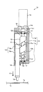
BACKGROUND ART
[0002]
Ball screw is known as a mechanism for converting rotary motion of a motor
into
linear motion. The ball screw includes a uniform spiral external thread formed
on a
shaft that is rotated by a motor, and an internal thread of a nut of a moving
portion that
is engaged with the external thread through steel balls. In this
configuration, when
the shaft rotates, the moving portion moves linearly in accordance with the
linear
motion of the nut. A required performance of the ball screw can be obtained,
for
example, by making the lead of the screw larger to increase the moving speed
of the
moving portion, and by making the lead of the screw smaller to increase a
thrust.
Because the thread is uniform, increasing the moving speed and increasing the
thrust
are in inverse relationship to each other.
[0003]
A spot welding gun disclosed in Patent Literature Document 1 is known as a
pressurizing apparatus which can improve the inverse relationship between the
moving speed and the thrust of this ball screw mechanism to generate a
pressurizing
force. This spot welding gun includes a circular cylindrical cam having a
hollow
portion, and a rod fitted into the hollow portion of the circular cylindrical
cam; when
rotating the circular cylindrical cam by a servo motor, the rod is caused to
move
linearly to perform a pressurizing operation. This mechanism is achieved by a
pair of
ball bearings each provided at a distal end of a pin projecting from the outer
1
CA 3059547 2019-10-22
English translation of
PCT/JP2019/007399
circumferential surface of the rod, and a pair of spiral cam grooves each
formed in the
inner circumferential surface of the circular cylindrical cam, into which the
respective
ball bearings are fitted. When the circular cylindrical cam rotates, the cam
grooves
are caused to rotate in accordance with the rotation of the circular
cylindrical cam, so
that the ball bearings moving in the cam grooves are caused to move linearly.
[0004]
Each cam groove forms an idle running section and a pressurizing section. In
the idle running section, a cam groove angle (cam lead) made between a plane
orthogonal to an axis of rotation and the cam groove is large, and the cam
groove is
inclined steeply. In contrast, in the pressurizing section, the cam groove
angle is
small, and the cam groove is inclined gently. In the idle running section, the
rod
reciprocates linearly at high speed but applies a small pressurizing force. In
the
pressurizing section, the rod reciprocates at low speed but applies a large
pressurizing force. In other words, the rod moves faster as the cam lead
becomes
larger (large lead cam groove), and moves slower while applying a larger
pressurizing
force as the cam lead becomes smaller (small lead cam).
CITATION LIST
PATENT LITERATURE DOCUMENT(S)
[0005]
Patent Literature Document 1: JP H07-124752A
SUMMARY OF THE INVENTION
TECHNICAL PROBLEM
[0006]
In a conventional cam mechanism in combination of a general cam groove and
a pair of rollers, if the cam lead in the idle running section and the cam
lead in the
pressurizing section are varied and the cam grooves are formed to extend in
excess
of one complete spiral turn in the pressurizing section, the stroke length
will be longer.
However, it is necessary that the diameter of the rollers and the width of the
cam
grooves be made larger so that one roller can withstand a large pressurizing
force.
Further, if the width of the cam groove is made larger, the pitch of the cam
groove
2
CA 3059547 2019-10-22
English translation of
PCT/JP2019/007399
" becomes larger in proportion to the increased width of the cam
groove. Accordingly,
it is difficult for the conventional structure to make the cam lead smaller in
the
pressurizing section.
[0007]
Patent Literature Document 1 as described above discloses a cam groove
formed to extend in a range of 90 degrees in the circumferential direction at
a position
corresponding to the pressurizing section. However, in order to ensure a
practical
stroke length (e.g., 30 mm) in the pressurizing section by the length of the
cam groove
formed in the range of 90 degrees, the cam lead inevitably becomes larger. For
this
reason, a large-sized motor with a large rotation torque is required to obtain
a large
pressurizing force.
[0008]
Further, Patent Literature Document 1 discloses two cam grooves offset from
each other by 180 degrees in phase in the circumferential direction of the
circumferential surface of the circular cylindrical cam; in this mechanism, a
load
applied to the ball bearings is evenly distributed. However, it is necessary
that the
cam grooves be formed without intersecting each other and with the two cam
grooves
separated from each other by a predetermined pitch, so that in order to
satisfy the
above prerequisite, the cam lead becomes inevitably larger or the stroke
length
becomes inevitably shorter.
[0009]
In view of the above, the present invention seeks to provide a pressurizing
apparatus and a welding apparatus, in which the cam lead in the pressurizing
section
can be made smaller and simultaneously the stroke length in the pressurizing
section
can be made longer.
SOLUTION TO PROBLEM
[0010]
To solve the above problem, the present invention seeks to provide a
pressurizing apparatus comprising: a cam member having an outer
circumferential
surface, in which a spiral lead cam groove is formed; a pressurizing member
including
a plurality of projections inserted into the lead cam groove, and configured
to move
3
CA 3059547 2019-10-22
=
English translation of
PCT/JP2019/007399
along an axis of rotation of the cam member when the cam member rotates,
wherein
the lead cam groove consists of a large lead cam groove inclined at a first
angle
relative to a plane orthogonal to the axis of rotation, and a small lead cam
groove
inclined at a second angle that is smaller than the first angle relative to
the plane
orthogonal to the axis of rotation, the large lead cam groove and the small
lead cam
groove being continuously connected to form the lead cam groove, and wherein
when
the plurality of projections are inserted into the large lead cam groove, a
projection
located at one end side of a row comes into contact with one of two side
surfaces of
the large lead cam groove and a projection located at another end side of the
row
comes into contact with the other one of the two side surfaces of the large
lead cam
groove, and when the plurality of projections are inserted into the small lead
cam
groove, each of the plurality of projections comes into contact with at least
one of one
side surface and the other side surface of two side surfaces of the small lead
cam
groove.
ADVANTAGEOUS EFFECTS OF THE INVENTION
[0011]
According to the present invention, there can be provided a pressurizing
apparatus and a welding apparatus, in which the cam lead in the pressurizing
section
can be made smaller and simultaneously the stroke length in the pressurizing
section
can be made longer.
BRIEF DESCRIPTION OF THE DRAWINGS
[0012]
FIG. 1 is a partly sectional side view illustrating a structure of a spot
welding
apparatus, to which a pressurizing apparatus according to the first embodiment
of the
present invention is applied.
FIG. 2 is a view illustrating a state in which two rollers are inserted into a
large
lead cam groove of a circular cylindrical cam of the spot welding apparatus
according
to the first embodiment.
FIG. 3 is a developed view of cam grooves, in which a large lead cam groove
and a small lead cam groove of the circular cylindrical cam are developed in
4
CA 3059547 2019-10-22
English translation of
PCT/JP2019/007399
accordance with rotation angles of the circular cylindrical cam in the range
of -720 to 0
to 720 degrees.
FIG. 4A is a plan view illustrating a state in which two rollers jutting out
from a
roller-attachment portion provided over a pressurizing shaft of the spot
welding
apparatus are inserted into the large lead cam groove.
FIG. 4B is a plan view illustrating a state in which the two rollers jutting
out from
the roller-attachment portion are inserted into the small lead cam groove.
FIG. 5 is a view illustrating a state in which the two rollers are inserted
into the
small lead cam groove of the circular cylindrical cam.
FIG. 6 is a side view illustrating a structure of four large lead cam grooves
and a
single small lead cam groove, which are formed in a circular cylindrical cam
of a spot
welding apparatus, to which a pressurizing apparatus according to the second
embodiment of the present invention is applied; in this figure, four pairs of
rollers are
inserted into the large lead cam grooves and some of the rollers are exposed
to view.
FIG. 7 is a side view illustrating a state in which some of the rollers are
exposed
to view while the four pairs of rollers are inserted into the small lead cam
groove.
FIG. 8A is a plan view illustrating a state in which four pairs of rollers
(each
including two as a pair) jutting out from a roller-attachment portion provided
over a
pressurizing shaft are inserted into the four large lead cam grooves.
FIG. 8B is a plan view illustrating a state in which the four pairs of rollers
are
inserted into the small lead cam groove.
FIG. 9 is a developed view of cam grooves, in which the four large lead cam
grooves and the single small lead cam groove that are formed in the
circumferential
surface of the circular cylindrical cam are developed in accordance with
rotation
angles of the circular cylindrical cam in the range of -1080 to 0 to 990
degrees.
DESCRIPTION OF EMBODIMENTS
[0013]
One embodiment of the present invention will be described below with reference
to the drawings.
<Structure of First embodiment>
FIG. 1 is a partly sectional side view illustrating a structure of a spot
welding
5
CA 3059547 2019-10-22
English translation of
PCT/JP2019/007399
apparatus, to which a pressurizing apparatus according to the first embodiment
of the
present invention is applied.
[0014]
The spot welding apparatus 10 shown in FIG. 1 is configured to weld metallic
material members such as a plurality of sheet metal members (workpieces) la,
lb
having been superposed one on another while pressurizing the metallic material
members under a large pressurizing force. The spot welding apparatus 10
includes
a main body frame 11 in the form of a circular cylindrical box, a circular
cylindrical cam
(cam member) 12 embedded into the interior of the main body frame 11, a
circular
cylindrical pressurizing shaft (pressurizing member) 13 fitted together with
the circular
cylindrical cam 12, and a servo motor 14 having a rotary shaft 14r that is
connected to
a rotary shaft 12r of the circular cylindrical cam 12.
[0015]
The main body frame 11 includes a circular cylindrical body frame 11a, an
upper
frame llb disposed on an upper portion of the body frame 11a, and a lower
frame 11c
disposed on a lower portion of the body frame 11a.
[0016]
The upper frame 11 b has a circular cylindrical cavity 11b1 penetrating
through
the upper frame 11 b in the upper-lower direction; in this cavity 11b1 , a
connector 16
for connecting the rotary shaft 14r of the servo motor 14 and the rotary shaft
12r of the
circular cylindrical cam 12 is received. The upper frame 11b has a through
hole
under the cavity 11b1 , and a ball bearing 17 is provided in the through hole.
An
upper portion of the rotary shaft 12r of the circular cylindrical cam 12 that
is connected
through the connector 16 is inserted into and rotatably supported by the ball
bearing
17.
[0017]
The lower frame 11c has a recess portion 11c1 at a position corresponding to
the through hole of the upper frame 11 b in the upper-lower direction, and a
ball
bearing 17 is provided in the recess portion 11c1 . A lower portion of the
rotary shaft
12r of the circular cylindrical cam 12 is inserted into and rotatably
supported by the
ball bearing 17. Further, the lower frame 11 c has a through hole beside the
recess
portion 11c1 , into which through hole a circular cylindrical slide bearing 18
is fitted. A
6
CA 3059547 2019-10-22
. ,
.
English translation of
PCT/JP2019/007399
circular cylindrical rod 13a of the pressurizing shaft 13 is inserted into and
slidably
received by the slide bearing 18.
[0018]
As seen in FIG. 2, the circular cylindrical cam 12 is a circular cylinder
having the
rotary shaft 12r, and a spiral cam groove (lead) is formed in the outer
circumferential
surface of the circular cylinder. The circular cylindrical cam 12 includes an
idle
running section 20a, in which a large lead cam groove 12a is formed (i.e., a
cam
groove angle (cam lead) of the spiral cam groove is a first angle). Further,
the
circular cylindrical cam 12 includes a pressurizing section 20b under the idle
running
section 20a, in which a small lead cam groove 12b is formed (i.e., the cam
groove
angle of the spiral cam groove is a second angle that is smaller than the
first angle).
The lead width of the large lead cam groove 12a in the upper-lower direction
is wider
than that of the small lead cam groove 12b. Further, the groove width of the
large
lead cam groove 12a is wider than that of the small lead cam groove 12b. It
should,
however, be noted that the first angle and the second angle are determined
based on
a moving speed and a pressurizing force required for the pressurizing shaft 13
to be
described later. Further, the large lead cam groove 12a and the small lead cam
groove 12b are continuously connected to form a lead cam groove defined in the
claims.
[0019]
To explain further, in the large lead cam groove 12a, the cam groove is
inclined
steeply at a first angle that is a steep cam groove angle larger than a
predetermined
angle. Meanwhile, in the small lead cam groove 12b, the cam groove is inclined
gently at a second angle that is a gentle cam groove angle smaller than the
predetermined angle. In a boundary portion between the large lead cam groove
12a
and the small lead cam groove 12b, side surfaces of the groove have rounded
corners.
It should be noted that the large lead cam groove 12a and the small lead cam
groove
12b are simply referred to as cam grooves 12a, 12b.
[0020]
FIG. 3 is a developed view of cam grooves 12a, 12b, in which the large lead
cam groove 12a and the small lead cam groove 12b formed in the circumferential
surface of the circular cylindrical cam 12 are developed in accordance with
rotation
7
CA 3059547 2019-10-22
English translation of
PCT/JP2019/007399
angles of the circular cylindrical cam 12 in the range of -720 to 0 to 720
degrees. As
illustrated in the range of 0 to 720 degrees of FIG. 3, the large lead cam
groove 12a
makes two complete spiral turns in the outer circumferential surface of the
circular
cylindrical cam 12. As illustrated in the range of 0 to -720 degrees, the
small lead
cam groove 12b makes two complete spiral turns in the outer circumferential
surface
of the circular cylindrical cam 12.
[0021]
The pressurizing shaft 13 shown in FIG. 1 includes a roller-attachment portion
13b fixed to an upper end of the rod 13a. As seen in the plan view of FIG. 4A,
two
rollers (projections) R1, R2 that are adjacent to each other and offset in the
upper-lower direction are attached to the roller-attachment portion 13b. These
rollers R1, R2 are rotatably attached to shafts protruding laterally from a
circular
arc-shaped side surface of the roller-attachment portion 13b. The rollers R1,
R2 are
inserted into the large lead cam groove 12a. Further, the rollers R1, R2 are
disposed
such that one roller R1 is located higher than the other roller R2. Although
the rollers
constitute projections defined in the claims, unlike the rollers, the
projections may be
non-rotatable protruding portions.
[0022]
As seen in FIG. 5, when the circular cylindrical cam 12 rotates, each of the
rollers R1, R2 is also inserted into the small lead cam groove 12b. The two
rollers
R1, R2 having been inserted into the small lead cam groove 12b are shown in
the
plan view of FIG. 4B. Insertion of the rollers R1, R2 into the cam groove 12a
and
insertion of the rod 13a into the slide bearing 18 as shown in FIG. 1 make it
possible
to combine the pressurizing shaft 13 and the circular cylindrical cam 12. A
downwardly protruding protrusion-like welding electrode 19 is fixed to a lower
end of
the pressurizing shaft 13. The welding electrode 19 is configured to weld a
plurality
of sheet metal members 1a, lb while pressurizing (pressing) them at a high
pressure.
[0023]
As seen in FIG. 2, when each of the rollers R1, R2 is inserted into the large
lead
cam groove 12a, the roller R1 located at an upper side (upper roller) comes
into
contact with the lower side surface (one side surface) of the cam groove 12a
by a
lower side of the circumferential surface thereof, and the roller R2 located
at a lower
8
CA 3059547 2019-10-22
English translation of
PCT/JP2019/007399
side (lower roller) comes into contact with the upper side surface (the other
side
surface) of the cam groove 12a by an upper side of the circumferential surface
thereof.
[0024]
Further, as seen in FIG. 5, when each of the rollers R1, R2 is inserted into
the
small lead cam groove 12b, the roller R1 and the roller R2 come into contact
with the
upper side surface or the lower side surface of the cam groove 12b by their
upper
sides and lower sides of the circumferential surfaces.
[0025]
When the circular cylindrical cam 12 rotates to the left (rotating from the
left side
to the right side in FIG. 2 as viewed from the front side of the figure) in
accordance
with the rotation of the servo motor 14 to the left (leftward rotation), the
lower roller R2
in the large lead cam groove 12a is pressed downward as shown by the arrow Y2
by
the upper steeply inclined surface of the cam groove 12a that is inclined at a
steep
angle. Each of the rollers R1, R2 moves downward by this downward pressing
force
(Y2). According to this downward movement of the rollers R1, R2, the
pressurizing
shaft 13 moves downward with the welding electrode 19 positioned at the front
end in
the moving direction.
[0026]
In contrast, when the servo motor 14 rotates to the right (rightward
rotation), the
circular cylindrical cam 12 rotates to the right (rotating from the right side
to the left
side in FIG. 2 as viewed from the front side of the figure), so that the upper
roller R1 in
the large lead cam groove 12a is pressed upward as shown by the arrow Y3 by
the
lower steeply inclined surface of the cam groove 12a. Each of the rollers R1,
R2
moves upward by this upward pressing force (Y3). According to this upward
movement of the rollers R1, R2, the pressurizing shaft 13 moves upward with
the
welding electrode 19 positioned at the rear end in the moving direction.
[0027]
Since the rollers R1, R2 are pressed by the steeply inclined surfaces of the
cam
groove 12a while the rollers R1, R2 move in the large lead cam groove 12a, the
rollers
R1, R2 move fast, and accordingly the pressurizing shaft 13 moves fast as
well.
[0028]
9
CA 3059547 2019-10-22
English translation of
PCT/JP2019/007399
_
Meanwhile, when the circular cylindrical cam 12 rotates to the left while each
of
the rollers R1, R2 is inserted into the small lead cam groove 12b as shown in
FIG. 5,
the roller R1 and the roller R2 are pressed downward as shown by the arrows
Y4a,
Y4b by the upper gently inclined surface of the cam groove 12b that is
inclined at a
gentle angle. Each of the rollers R1 , R2 moves downward by this downward
pressing force, so that the pressurizing shaft 13 moves downward with the
welding
electrode 19 positioned at the front end in the moving direction.
[0029]
In contrast, when the circular cylindrical cam 12 rotates to the right, the
rollers
R1, R2 are pressed upward as shown by the arrows Y5a, Y5b by the lower gently
inclined surface of the cam groove 12b. Each of the rollers R1, R2 moves
upward by
this upward pressing force, so that the pressurizing shaft 13 moves upward
with the
welding electrode 19 positioned at the rear end in the moving direction.
[0030]
Since the roller R1 and the roller R2 are pressed simultaneously by the gently
inclined surface of the small lead cam groove 12b while the rollers R1, R2
move
downward, the pressing force applied to the rollers R1, R2 is distributed.
[0031]
<Operation of First embodiment>
Next, description will be given to a pressurizing operation, in which a
plurality of
sheet metal members la, lb superposed one on another are pressed and welded
together using the spot welding apparatus 10, to which the pressurizing
apparatus
according to the first embodiment is applied.
[0032]
As a precondition, it is supposed that as seen in FIG. 3, the rollers R1, R2
are
inserted into the large lead cam groove 12a at the uppermost position H1 of
the idle
running section 20a. At this insertion position of the rollers R1, R2 into the
cam
groove 12a, the circular cylindrical cam 12 rotates approximately by 540
degrees. At
this time, the welding electrode 19 of the pressurizing shaft 13 is located at
the
uppermost position.
[0033]
When the circular cylindrical cam 12 rotates to the left by the leftward
rotation of
CA 3059547 2019-10-22
English translation of
PCT/JP2019/007399
the servo motor 14, the lower roller R2 inserted into the large lead cam
groove 12a is
pressed downward (as shown by the arrow Y2 in FIG. 2) by the steeply inclined
surface of the cam groove 12a and thus moves fast. Accordingly, the
pressurizing
shaft 13 moves fast downward, so that as seen in FIG. 3, the welding electrode
19
moves fast downward as shown by the arrow Y6.
[0034]
By this fast movement, among the rollers R1, R2, the leading roller R2 located
frontward in the moving direction crosses downward the boundary H2 between the
large lead cam groove 12a and the small lead cam groove 12b, and then the
trailing
roller R1 located rearward in the moving direction reaches the boundary H2. At
this
position, the roller R1 and the roller R2 lie on both sides of the rotation
angle of -90
degrees (-90 degrees exists between the roller R1 and the roller R2). At this
position
around the rotation angle of -90 degrees, the two rollers R1, R2 are inserted
into the
small lead cam groove 12b, and the welding electrode 19 is located at a
position
immediately above and adjacent to the sheet metal members la, lb.
[0035]
The rollers R1, R2 in this position are pressed downward simultaneously (as
shown by the arrows Y4a, Y4b in FIG. 5) by the gently inclined surface of the
cam
groove 12b, so that the pressing force applied to the rollers R1, R2 by the
gently
inclined surface is distributed. In other words, a load (pressing force)
applied to one
roller R1 or R2 is small. However, since the side surfaces of the small lead
cam
groove 12b, by which the rollers R1, R2 are pressed, are gently inclined
surfaces, the
pressing force applied to the rollers R1, R2 by the gently inclined surfaces
is larger
than that applied by the steeply inclined surfaces.
[0036]
Further, the rollers R1, R2 move downward, so that the welding electrode 19
presses the sheet metal members la, lb by the pressurizing force equal to the
load
(pressing force) applied to all the rollers R1, R2 in accordance with the
movement of
the rollers R1, R2. During the pressurization of the welding electrode 19, the
sheet
metal members la, lb are welded together by the welding electrode 19. When the
rollers R1, R2 move further downward, the rollers R1, R2 reach the lowermost
position H3 of the small lead cam groove 12b and stop.
11
CA 3059547 2019-10-22
English translation of
PCT/JP2019/007399
[0037]
It should be noted that the number of rollers inserted into the cam groove
12a,
12b may be three or more. For example, if the number of rollers is three, when
the
rollers are inserted into the large lead cam groove 12a, the roller located at
one end
side of a row comes into contact with the upper steeply inclined surface of
the cam
groove 12a by the upper side of the circumferential surface thereof, and the
roller
located at the other end side of the row comes into contact with the lower
steeply
inclined surface of the cam groove 12a by the lower side of the
circumferential surface
thereof. Further, in the small lead cam groove 12b, the plurality of rollers
come into
contact with the upper and lower surfaces of the cam groove 12b.
[0038]
<Advantageous effects of First embodiment>
As described above, the spot welding apparatus 10, to which the pressurizing
apparatus according to the first embodiment is applied, includes: the circular
cylindrical cam 12 having the outer circumferential surface, in which the
spral lead
cam groove is formed; the pressurizing shaft 13 including a plurality of
rollers R1, R2
protruding therefrom and inserted into the lead cam groove, and configured to
move
along an axis of rotation of the circular cylindrical cam 12 when the circular
cylindrical
cam 12 rotates. The lead cam groove consists of the large lead cam groove 12a
zo inclined at a first angle relative to a plane orthogonal to the rotary
shaft 12r, and the
small lead cam groove 12b inclined at a second angle that is smaller than the
first
angle relative to the plane orthogonal to the rotary shaft 12r; the large lead
cam
groove 12a and the small lead cam groove 12b are continuously connected to
form
the lead cam groove. When the plurality of rollers R1, R2 are inserted into
the large
lead cam groove 12a, the roller R1, R2 located at one end side of a row comes
into
contact with one of two side surfaces of the large lead cam groove 12a and the
roller
R1, R2 located at another end side of the row comes into contact with the
other one of
the two side surfaces of the large lead cam groove 12a, and when the plurality
of
rollers R1, R2 are inserted into the small lead cam groove 12b, each of the
plurality of
rollers R1, R2 comes into contact with at least one of the one side surface
and the
other side surface of the small lead cam groove 12b.
[0039]
12
CA 3059547 2019-10-22
English translation of
_
PCT/JP2019/007399
With this configuration, when the circular cylindrical cam 12 rotates in
accordance with the rotation of the servo motor 14 on condition that the
rotary shaft of
the circular cylindrical cam 12 is coupled to a rotary shaft of the servo
motor 14, the
plurality of rollers R1, R2 move, for example, in the large lead cam groove
12a and
then enter and move in the small lead cam groove 12b. While the rollers R1, R2
move in the large lead cam groove 12a, the roller R1, R2 located at one end
side of
the row is pressed by the steeply inclined surface of the large lead cam
groove 12a
inclined at the first angle that is steeper than the second angle.
Accordingly, each of
the rollers R1, R2 moves fast in a direction of the shaft, so that the
pressurizing shaft
13 moves fast in the direction of the rotary shaft in accordance with the
movement of
the rollers R1, R2.
[0040]
Meanwhile, while the rollers R1, R2 move in the small lead cam groove 12b, the
plurality of rollers R1, R2 are pressed simultaneously by the gently inclined
surface of
the small lead cam groove 12b that is inclined at the second angle gentler
than the
first angle. Accordingly, the force applied to the rollers R1, R2 by the
gently inclined
surface is distributed. In other words, since the pressing force applied to
one roller
R1 or R2 becomes smaller, the size of the rollers R1, R2 can be reduced. Since
the
groove width and the cam ridge of the small lead cam groove 12b that are
formed
spirally in the circumferential surface of the circular cylindrical cam 12 are
reduced in
size in accordance with this downsizing of the rollers R1, R2, it is possible
to reduce
the size of the cam lead.
[0041]
Since the pressing force applied by the gently inclined surface of the small
lead
cam groove 12b is distributed by the plurality of rollers R1, R2, the lead cam
groove is
less likely to be damaged due to the pressing force applied to the rollers R1,
R2.
[0042]
With this configuration, since the small lead cam groove 12b extending in
excess of at least one complete spiral turn is formed in the outer
circumferential
surface of the circular cylindrical cam 12, the stroke length of the
pressurizing section
is made longer, If the cam lead is smaller in the pressurizing section, the
rotation
torque of the circular cylindrical cam 12 may be made smaller in accordance
thereto.
13
CA 3059547 2019-10-22
English translation of
PCT/JP2019/007399
It is therefore possible to make the cam lead smaller in the pressurizing
section and
simultaneously to make the stroke length of the pressurizing section longer in
the
pressurizing section. Accordingly, the servo motor 14 for rotating the
circular
cylindrical cam 12 can be fabricated by a small-sized servo motor with a low
rotation
torque.
[0043]
According to the technique disclosed in Patent Literature Document 1, the
circular cylindrical cam 12 has a small lead cam groove (lead) with one
quarter spiral
turn; suppose that the lead width of this quarter cam groove in the upper-
lower
direction is, for example, 30 mm as a practical stroke length, the lead width
becomes
120 mm for one complete turn and 240 mm for two complete turns. In contrast,
according to this embodiment, suppose that the pressurizing force of a general
welding gun is 5,000 N, the lead width can be 30 mm for two complete turns, so
that
as compared with Patent Literature Document 1, the ratio of the lead width
becomes
one-eighth (i.e., 30 mm / 240 mm = 1/8). For this reason, according to this
embodiment, a small-sized servo motor 14 with a rotation torque of one-eighth
of the
motor used in Patent Literature Document 1 can be used.
[0044]
In the spot welding apparatus 10, to which the pressurizing apparatus is
applied,
various advantages, such as reducing the size of the spot welding apparatus
10,
reducing the electric power consumption, and reducing the cost, can be
obtained by
the use of this small-sized servo motor 14.
[0045]
Since the rollers R1, R2 do not receive a large load (pressurizing force) in
the
idle running section where a workpiece is not pressurized, among the two
rollers R1,
R2, only one roller R2 located at one end side comes into contact with the
side
surface of the large lead cam groove 12a to cause the pressurizing shaft 13 to
move
fast. Accordingly, the cycle time required for pressurizing a workpiece in the
pressurizing process can be made shorter for instance.
.. [0046]
<Configuration of Second embodiment>
FIG. 6 is a side view illustrating a structure of four large lead cam grooves
41-44
14
CA 3059547 2019-10-22
English translation of
PCT/JP2019/007399
and a single small lead cam groove 45, which are formed in a circular
cylindrical cam
40 of a spot welding apparatus, to which a pressurizing apparatus according to
the
second embodiment of the present invention is applied; in this figure, four
pairs of
rollers R11-R18 are inserted into the large lead cam grooves 41-44 and some of
the
rollers R11, R16, R17, R18 are exposed to view.
[0047]
FIG. 7 is a side view illustrating the structures of the four large lead cam
grooves
41-44 and the single small lead cam groove 45 as well as illustrating a state
in which
some of the rollers R11, R12, R13, R18 are exposed to view while the four
pairs of
rollers R11-R18 are inserted into the small lead cam groove 45.
[0048]
FIG. 8A is a plan view illustrating a state in which four pairs (four sets) of
rollers
(projections) R11, R12; R13, R14; R15, R16; R17, R18 (each including two as a
pair
(a set)) jutting out from the roller-attachment portion 33b provided over the
pressurizing shaft 33 are inserted into the four large lead cam grooves 41,
42, 43, 44.
FIG. 8B is a plan view illustrating a state in which the four pairs of rollers
R11-R18 are
inserted into the small lead cam groove 45. It should be noted that the large
lead
cam grooves 41-44 and the small lead cam groove 45 are continuously connected
to
form the lead cam groove defined in the claims.
[0049]
FIG. 9 is a developed view of cam grooves 41-44, 45, in which the four large
lead cam grooves 41-44 and the single small lead cam groove 45 that are formed
in
the circumferential surface of the circular cylindrical cam (cam member) 40
are
developed in accordance with rotation angles of the circular cylindrical cam
40 in the
range of -1080 to 0 to 990 degrees.
[0050]
The spot welding apparatus 30 according to the second embodiment and the
spot welding apparatus 10 according to the first embodiment as shown in FIG. 1
are
different in that the circular cylindrical cam 40 and the pressurizing shaft
(pressurizing
member) 33 are configured as described below.
[0051]
Namely, as seen in FIG. 6, the circular cylindrical cam 40 rotatable about the
CA 3059547 2019-10-22
English translation of
PCT/JP2019/007399
rotary shaft 40r has four large lead cam grooves 41-44 (see FIG. 9) formed in
the
outer circumferential surface thereof at a steep angle; the four large lead
cam grooves
41-44 are disposed parallel to and separated from each other. Lower ends of
the
cam grooves 41-44 are connected to an upper end of the single small lead cam
groove 45 that is formed to be inclined at a gentle angle. A portion of the
circular
cylindrical cam 40 where the four large lead cam grooves 41-44 are formed is
an idle
running section 50a, and a portion of the circular cylindrical cam 40 where
the single
small lead cam groove 45 is formed is a pressurizing section 50a. At boundary
portions between the large lead cam grooves 41-44 and the small lead cam
groove 45,
side surfaces of the grooves partly have rounded corners (see FIG. 9).
[0052]
The large lead cam groove 41 is referred to as a first cam groove 41, the
large
lead cam groove 42 is referred to as a second cam groove 42, the large lead
cam
groove 43 is referred to as a third cam groove 43, and the large lead cam
groove 44 is
referred to as a fourth cam groove 44.
[0053]
As seen in FIG. 8A, the pressurizing shaft 33 includes an annular-shaped
roller-attachment portion 33b, and two rods 33a1, 33a2 protruding downward
from a
lower surface of the roller-attachment portion 33b and disposed opposite to
each
other. A protrusion-like welding electrode 19a1, 19a2 is fixed to a lower end
of each
of the rods 33a1, 33a2.
[0054]
Four pairs of rollers R11-R18 are attached to an inner circumferential surface
of
the roller-attachment portion 33b such that they are arranged
circumferentially at
regular intervals. The rollers
R11-R18 are rotatably attached to shafts each
protruding from the inner circumferential surface of the roller-attachment
portion 33b
toward the center of the inner circle. The rollers R11-R18 are insertable into
the
large lead cam grooves 41-44 or the small lead cam groove 45 (see FIG. 8B).
[0055]
The rollers R11-R18 are arranged on the inner circumferential surface of the
roller-attachment portion 33b with height differences made therebetween such
that
they are aligned spirally in the large lead cam grooves 41-44 and in the small
lead
16
CA 3059547 2019-10-22
, ,
English translation of
PCT/JP2019/007399
- cam groove 45. In other words, the rollers R11-R18 are attached to
the inner
circumferential surface of the roller-attachment portion 33b at slant height
positions
such that when the rollers R11-R18 are inserted into the small lead cam groove
45 as
shown in FIG. 9, the rollers R11-R18 come into contact with the upper side
surface or
the lower side surface of the cam groove 45. As seen in FIG. 9, the rollers
R11-R18
are arranged at the same angle as the inclined angle of the small lead cam
groove
12b.
[0056]
In the large lead cam groove 41-44 shown in FIG. 9, a pair of rollers R11, R12
(also referred to as the first set of rollers R11, R12) located at the highest
position are
inserted into the first cam groove 41, and then a pair of rollers R13, R14
(also referred
to as the second set of rollers R13, R14) located at the second highest
position are
inserted into the second cam groove 42. Further, a pair of rollers R15, R16
(also
referred to as the third set of rollers R15, R16) located at the third highest
position are
inserted into the third cam groove 43, and then a pair of rollers R17, R18
(also
referred to as the fourth set of rollers R17, R18) located at the lowest
position are
inserted into the fourth cam groove 44.
[0057]
When the first set of rollers R11, R12 are inserted into the first cam groove
41,
the roller R11 located at the upper side comes into contact with the lower
side surface
of the first cam groove 41 by the lower side of the circumferential surface of
the roller
R11 and the roller R12 located at the lower side comes into contact with the
upper
side surface of the first cam groove 41 by the upper side of the
circumferential surface
of the roller R12.
[0058]
When the second set of rollers R13, R14 are inserted into the second cam
groove 42, the roller R13 located at the upper side comes into contact with
the lower
side surface of the second cam groove 42 by the lower side of the
circumferential
surface of the roller R13 and the roller R14 located at the lower side comes
into
contact with the upper side surface of the second cam groove 42 by the upper
side of
the circumferential surface of the roller R14.
[0059]
17
CA 3059547 2019-10-22
_
English translation of
PCT/JP2019/007399
-
When the third set of rollers R15, R16 are inserted into the third cam groove
43,
the roller R15 located at the upper side comes into contact with the lower
side surface
of the third cam groove 43 by the lower side of the circumferential surface of
the roller
R15 and the roller R16 located at the lower side comes into contact with the
upper
side surface of the third cam groove 43 by the upper side of the
circumferential
surface of the roller R16.
[0060]
When the fourth set of rollers R17, R18 are inserted into the fourth cam
groove
44, the roller R17 located at the upper side comes into contact with the lower
side
surface of the fourth cam groove 44 by the lower side of the circumferential
surface of
the roller R17 and the roller R18 located at the lower side comes into contact
with the
upper side surface of the fourth cam groove 44 by the upper side of the
circumferential surface of the roller R18.
[0061]
When the circular cylindrical cam 40 (see FIG. 6) rotates to the left, the
lower
rollers R12, R14, R16, R18, among the four pairs of rollers R11-R18 in the
large lead
cam grooves 41-44, are pressed downward simultaneously by the upper steeply
inclined surfaces of the respective cam grooves 41-44. Each of the rollers R11-
R18
moves downward by this downward pressing force, so that the pressurizing shaft
40
moves downward with the welding electrodes 19a1, 19a2 positioned at the front
end
in the moving direction.
[0062]
In contrast, when the circular cylindrical cam 40 (see FIG. 6) rotates to the
right,
the upper rollers R11, R13, R15, R17, among the four pairs of rollers R11-R18
in the
large lead cam grooves 41-44, are pressed upward by the lower steeply inclined
surfaces of the respective cam grooves 41-44. Each of the rollers R11-R18
moves
upward by this upward pressing force, so that the pressurizing shaft 33 moves
upward
with the welding electrodes 19a1, 19a2 positioned at the rear end in the
moving
direction.
[0063]
Since the rollers R11-R18 are pressed by the steeply inclined surfaces of the
cam grooves 41-44 while the rollers R11-R18 move in the large lead cam grooves
18
CA 3059547 2019-10-22
English translation of
PCT/JP2019/007399
41-44, the rollers R11-R18 move fast, and accordingly the pressurizing shaft
33
moves fast as well.
[0064]
Further, as seen in FIG. 9, when the plurality of rollers R11-R18 are inserted
into
the small lead cam groove 45, the rollers R11-R18 come into contact with the
upper
side surface or the lower side surface of the small lead cam groove 45 by
their upper
sides and lower sides of the circumferential surfaces.
[0065]
When the circular cylindrical cam 40 (see FIG. 7) rotates to the left while
each of
the rollers R11-R18 is inserted into the small lead cam groove 45, the
plurality of
rollers R11-R18 are pressed downward simultaneously by the upper gently
inclined
surface of the cam groove 45. Each of the rollers R11-R18 moves downward by
this
downward pressing force, so that the pressurizing shaft 33 moves downward with
the
welding electrodes 19a1 , 19a2 positioned at the front end in the moving
direction.
.. [0066]
Since the plurality of rollers R11-R18 (four pairs at the maximum) are pressed
simultaneously by the gently inclined surface of the small lead cam groove 45
while
the rollers R11-R18 move downward, the pressing force (load) applied to the
rollers
R11-R18 is distributed.
[0067]
In contrast, when the circular cylindrical cam 40 (see FIG. 7) rotates to the
right,
the plurality of rollers R11-R18 (four pairs at the maximum) are pressed
upward by the
lower gently inclined surface of the cam groove 45. Each of the rollers R11-
R18
moves upward by this upward pressing force, so that the pressurizing shaft 33
moves
upward with the welding electrodes 19a1, 19a2 positioned at the rear end in
the
moving direction.
[0068]
<Operation of Second embodiment>
Next, description will be given to a pressurizing operation, in which a
plurality of
sheet metal members la, lb (see FIG. 1) superposed one on another are welded
together using the spot welding apparatus 30, to which the pressurizing
apparatus
according to the second embodiment is applied.
19
CA 3059547 2019-10-22
English translation of
PCT/JP2019/007399
[0069]
As a precondition, it is supposed that as seen in FIG. 9, each of the rollers
R11-R18 is inserted into the corresponding large lead cam groove 41-44 at the
uppermost position H11 of the idle running section 50a. At this insertion
position of
the rollers R11-R18 into the cam grooves 41-44, the rotation angle of the
circular
cylindrical cam 40 is approximately 600-990 degrees. At this time, the welding
electrodes 19a1, 19a2 of the pressurizing shaft 13 are located at the
uppermost
position.
[0070]
When the circular cylindrical cam 40 rotates to the left by the leftward
rotation of
the servo motor 14 (see FIG. 1), the lower rollers R12, R14, R16, R18, among
the
pairs of rollers R11-R18 inserted into the corresponding large lead cam
grooves 41-44,
are pressed downward by the upper steeply inclined surfaces of the cam grooves
41-44 and thus move fast. Accordingly, the pressurizing shaft 33 moves fast
downward, so that the welding electrodes 19a1, 19a2 move fast downward as
well.
[0071]
By this movement, among the rollers R11-R18, the leading roller R18 located in
the frontmost position in the moving direction first crosses downward the
boundary
H12 between the first cam groove 41 and the small lead cam groove 45, and then
the
trailing roller R17 located rearward of the roller R18 crosses the boundary
H12
downward. Next, the third set of rollers R16, R15 cross the boundary H12
downward.
Then, the second set of rollers R14, R13 cross the boundary H12 downward.
After
that, the first set of rollers R12, R11 move downward to reach the boundary
H12. In
this reaching position, the welding electrodes 19a1, 19a2 are located at a
position
immediately above and adjacent to the sheet metal members la, lb.
[0072]
The rollers R11-R18 are pressed downward simultaneously by the upper gently
inclined surface of the small lead cam groove 45, so that the pressing force
applied to
the rollers R11-R18 by the gently incline surface is distributed. In other
words, a load
(pressing force) applied to one roller is small. However, since the side
surfaces of
the small lead cam groove 45, by which the rollers R1-R18 are pressed, are
gently
inclined surfaces, the pressing force applied to the rollers R11-R18 by the
gently
CA 3059547 2019-10-22
English translation of
PCT/JP2019/007399
inclined surfaces is larger than that applied by the steeply inclined
surfaces.
[0073]
Further, the rollers R11-R18 move downward, so that the welding electrodes
19a1, 19a2 press the sheet metal members la, lb by the pressurizing force
equal to
the load (pressing force) applied to all the rollers R11-R18 in accordance
with the
movement of the rollers R11-R18. During
the pressurization of the welding
electrodes 19a1, 19a2, the sheet metal members 1a, lb are welded together by
the
welding electrode 19a1 or the welding electrode 19a2. When the rollers R11-R18
move further downward, the trailing roller R11 located at the rear end in the
traveling
direction reaches the lowermost position H3 of the small lead cam groove 45
and
stops.
[0074]
Although the above-described embodiment includes four large lead cam
grooves 41-44, the number of large lead cam grooves is not limited; for
example, the
number of large lead cam grooves may be two or more, and plural sets of
rollers, each
including a plurality of rollers as a set, may be inserted into the
corresponding large
lead cam grooves.
[0075]
<Advantageous effects of Second embodiment>
As described above, in the spot welding apparatus 30, to which the
pressurizing
apparatus according to the second embodiment is applied, the lead cam groove
includes four large lead cam grooves 41-44 that are branched from a single
small lead
cam groove 45. The pressurizing shaft 33 includes four sets of rollers R11-R18
each
including two rollers. The four sets of rollers R11-R18 are inserted into the
four large
lead cam grooves 41-44, respectively, and all the four sets of rollers R11-R18
are
inserted into the single small lead cam groove 45.
[0076]
With this configuration, the four sets of rollers R11-R18 are pressed
simultaneously by the gently inclined surface of the single small lead cam
groove 45,
the pressing force is reduced to one quarter as compared with an alternative
configuration in which one set of rollers are pressed simultaneously by the
gently
inclined surface. In other words, since the pressing force applied to one
roller is
21
CA 3059547 2019-10-22
English translation of
PCT/1P2019/007399
greatly reduced, the size of the rollers can be greatly reduced. Further, the
cam
ridge by which the reaction force of the roller is received can be reduced in
width. In
accordance with this downsizing of the rollers, the cam lead of the small lead
cam
groove 45 that is formed spirally in the outer circumferential surface of the
circular
cylindrical cam 40 can be reduced in size.
[0077]
Since the pressing force applied by the gently inclined surface of the small
lead
cam groove 45 is distributed by the plurality of rollers R11-R18, the lead cam
groove
is less likely to be damaged due to the pressing force applied to the rollers
R11-R18.
[0078]
With this configuration, since the small lead cam groove 45 extending in
excess
of at least one complete spiral turn is formed in the outer circumferential
surface of the
circular cylindrical cam 40, the stroke length of the pressurizing section is
made longer.
If the cam lead is smaller in the pressurizing section, the rotation torque of
the circular
cylindrical cam 40 may be made smaller in accordance thereto. It is therefore
possible to make the cam lead smaller in the pressurizing section and
simultaneously
to make the stroke length of the pressurizing section longer in the
pressurizing section.
Accordingly, the servo motor 14 for rotating the circular cylindrical cam 40
can be
fabricated by a small-sized servo motor with a low rotation torque.
[0079]
Various changes and/or modifications may be made where appropriate to
specific configurations of the above-described embodiments without departing
from
the gist of the present invention. Other than the above-described spot welding
apparatus 10, 30, to which the pressurizing apparatus has been applied, the
pressurizing apparatus according to the present invention is applicable to
other
apparatuses, such as a friction stir welding apparatus, a press working
apparatus, a
press-fitting apparatus, a swaging apparatus, a seam welding apparatus, and a
projection welding apparatus.
DESCRIPTION OF REFERENCE NUMERALS
[0080]
la, lb sheet metal member
22
CA 3059547 2019-10-22
English translation of
PCT/JP2019/007399
10, 30 spot welding apparatus
11 main body frame
11 a body frame
lib upper frame
11 bl cavity
11c lower frame
lidl recess portion
12, 40 circular cylindrical cam
12r, 40r rotary shaft of the circular cylindrical cam
12a, 41-44 large lead cam groove
12b, 45 small lead cam groove
13, 33 pressurizing shaft
13a, 33a1, 33a2 rod
13b, 33b roller-attachment portion
14 servo motor
14r rotary shaft of the servo motor
16 connector
17 ball bearing
18 slide bearing
19, 19a1, 19a2 welding electrode
20a, 50a idle running section
20b, 50b pressurizing section
R1, R2, R11-R18 roller
23
CA 3059547 2019-10-22