Note: Descriptions are shown in the official language in which they were submitted.
CA 03059642 2019-10-10
KRI-0009-CA
PRESS-IN CONNECTING ELEMENT AND METHOD FOR ANCHORING PRESS-IN
CONNECTING ELEMENTS IN A PERMANENTLY DEFORMABLE FLAT METAL MATERIAL OR
COMPONENTS OR WORKPIECES PRODUCED THEREFROM
The invention relates to a press-in connecting element and a method for
anchoring press-in
connecting elements in a permanently deformable flat metal material or
components or workpieces
produced therefrom according to the preamble of patent claim 1 and 12.
Press-in connecting elements which are inserted or anchored in a permanently
deformable flat
metal material, in particular a metal sheet or a component or workpiece
produced therefrom, by
joining and subsequent pressing, are well-known.
Such press-in connecting elements are often designed in the form of press-in
nuts with an internal
thread or press-in sleeves without an internal thread. As a result of the
corresponding choice of
material hardness of the material of the press-in connecting element in
comparison to the
permanently deformable flat metal material, only the flat metal material, in
particular metal sheet
and not the press-in connecting element is deformed per se during the press-in
process.
Press-in connecting elements generally have a sleeve-like main body having a
head section and a
shaft section, which adjoins the head section along a longitudinal axis and is
cross-section reduced
in comparison to the head section. The shaft section comprises a joining
section, which directly
adjoins the head section, the lateral surface of which is designed as a knurl
or other non-round or
polygonal lateral surface for fixing the press-in connecting element in the
metal sheet in a
rotationally-fixed manner. A preferably annular press-in section is provided
on the free end of the
shaft section opposite the head section, which press-in section forms an
undercut between the
joining section and the press-in section.
After joining, i.e. after inserting the joining section of the shaft section
of the press-in connecting
element into a joining opening prepared in the metal sheet, also called pre-
punching, the
connecting or anchoring of the connecting element takes place through pressing
by plastically
deforming the metal sheet in the region of the joining opening, in which metal
sheet the press-in
connecting element is to be anchored. For the connection produced between the
sheet and the
connecting element by joining and pressing, it is required, inter alia, that
this connection has a
high resistance to pressing out of the press-in connecting element from the
metal sheet through
axially acting forces as well as a high resistance to twisting, i.e. a
sufficiently high torque
absorption. This is achieved, inter alia, by the material of the metal sheet
flowing during pressing
into the undercut between the joining section and the press-in section.
Joining and pressing of the
press-in connecting elements often takes place using a so-called punching head
in a tool, by way
1
CA 03059642 2019-10-10
KRI-0009-CA
of example a follow-on tool, in which the respective workpiece or component is
also produced from
the metal sheet, e.g. by punching and/or bending.
When inserting and joining the press-in connecting element into the metal
sheet or into the pre-
punching in the metal sheet, as a result of an unfavorable size of the joining
section and/or of the
press-in section of the shaft section in relation to the pre-punching in the
metal sheet, an
undesirable material displacement of the metal sheet in the axial direction
and possibly into the
undercut section may disadvantageously occur, which can have a negative impact
on the
subsequent punching process, and can in particular lead to an incorrect
positioning and/or fixing of
the connecting element.
On that basis, it is the object of the invention to provide a press-in
connecting element and a
method for anchoring same in a permanently deformable flat metal material or
component or
workpiece produced therefrom, wherein an undesired material displacement in
the axial direction
when joining the press-in connecting element can be avoided. The object is
achieved on the basis
of a press-in connecting element in accordance with the features of the
preamble of patent claim 1
by the characterizing features thereof. Furthermore, in order to achieve this
object, a method for
anchoring press-in connecting elements in a permanently deformable flat metal
material, in
particular metal sheet or components or workpieces produced therefrom, is
designed in
accordance with patent claim 12.
An essential aspect of the press-in connecting element according to the
invention can be seen in
that the knurled joining section has a first diameter and the press-in section
has a second
diameter and the second diameter is smaller than the first diameter, the
second diameter
corresponding approximately to the initial diameter of the joining section
before the knurl is
formed in the lateral surface or approximately to the first diameter minus
half of the knurl depth.
Therefore, the diameter of the knurl or joining section of the shaft section
in comparison to the
punching section of the shaft section of the press-in connecting element is
designed particularly
advantageously in such a manner that there is no material displacement in the
axial direction
either through the punching section or through the knurl or joining section
when inserting the
press-in connecting element into a sheet element. Advantageously, the punching
process is
therefore not negatively influenced. The material displacement is almost
exclusively produced by
the punching tool or a die with annular embossing collar.
In a preferred embodiment, the knurl is formed as a so-called RAA knurl having
a plurality of
grooves running parallel to the longitudinal axis. Such RAA knurls form a
serrated profile oriented
in the longitudinal direction of the connecting element and thus also in the
joining direction of the
connecting element, such that a material displacement into the grooves of the
knurl which are
2
CA 03059642 2019-10-10
KRI-0009-CA
inserted between two serrations is possible when joining. Furthermore
advantageously, an axial
material displacement is effectively prevented by aid of the dimensioning
according to the
invention of the diameters of the joining and press-in section of the press-in
connecting element
by virtue of the orientation of the grooves parallel to the longitudinal axis.
Particularly preferably, the knurl formed as an RAA knurl has a spacing and a
profile angle and the
difference between the first and second diameter is according to the invention
dependent on the
spacing of the knurl, wherein the following relationship exists between the
first and second
diameter dl, d2 and the spacing t:
d1 ¨ 0.5 *t = d2
The RAA knurl is standardized in DIN82 and may by way of example have
standardized spacings of
0.5 mm, 0.6 mm, 0.8 mm, 1.0 mm, 1.2 mm or 1.6 mm. By way of example, a spacing
t of 0.8
mm and a profile angle of 900 is particularly preferable.
Particularly advantageously, in the case of the press-in connecting element
according to the
invention, the first diameter is selected such that it corresponds to the
diameter of a virtual
circumference around the longitudinal axis, on which the outer tips of the
knurl come to rest.
According to the invention, the knurl depth corresponds to the difference of
the radius of the
virtual circumference around the longitudinal axis, on which the outer tips of
the knurl or the
serrations of the serrated profile come to rest, and the radius of the further
virtual circumference
around the longitudinal axis, on which the inner tips of the knurl or the
serrations of the serrated
profile come to rest.
Further advantageously, an annular undercut section is formed between the
knurled joining
section and the press-in section, which undercut section preferably forms a
recess which is groove-
shaped and/or annular by way of example and extends concentrically to the
longitudinal axis, in
which recess the material of the metal sheet surrounding the press-in
connecting element is
plastically deformed when pressing the press-in connecting element with the
metal sheet. As a
result of the "filling" of the annular undercut section with material of the
metal sheet caused
hereby, the press-in connecting element is additionally anchored in the metal
sheet alongside the
knurl of the joining section and is secured in particular against twisting.
Particularly preferably, the annular undercut section has a third diameter
which is smaller than the
second diameter and to be specific the difference between the second and third
diameter is
preferably between 0.25 times and one times the spacing of the knurl formed as
an RAA knurl.
With the mentioned dimensioning of the annular undercut section in relation to
the diameters of
3
CA 03059642 2019-10-10
KRI-0009-CA
the joining and press-in section, an optimal anchoring of the press-in
connecting element in the
metal region could be achieved with a good joining performance. The press-in
section is preferably
formed by an annular press-in collar, via which a self-punching function can
also be provided.
A prefabricated assembly comprising a press-in connecting element according to
the invention and
a permanently deformable flat metal material or a component or workpiece
produced therefrom is
likewise the object of the invention, wherein the press-in connecting element
is inserted into the
permanently deformable flat metal material or a component or workpiece
produced therefrom, by
joining and pressing, or is anchored therein.
A further object of the invention is a method for anchoring a press-in
connecting element in a
permanently deformable flat metal material, in particular a metal sheet or a
component or
workpiece produced therefrom, by joining and pressing, wherein the press-in
connecting element
has a head section and a shaft section, which adjoins the head section along a
longitudinal axis
and which is set back relative to the head section, said shaft section
comprising at least a joining
section, which directly adjoins the head section, with a lateral surface
having a knurl and a press-
in section, which adjoins the joining section along the longitudinal axis.
Particularly
advantageously, when joining the press-in connecting element into the
permanently deformable
flat metal material, in particular metal sheet, the press-in connecting
element is inserted, without
material displacement of the flat material or metal sheet along the
longitudinal axis or in the
joining direction, into the permanently deformable flat metal material, in
particular metal sheet,
preferably a joining opening or pre-punching provided therein. Thus, when
joining the press-in
connecting element into the flat material or metal sheet, the material of the
flat material or metal
sheet surrounding the press-in connecting element is displaced exclusively
radially with respect to
the longitudinal axis or joining direction. As a result, the subsequent press-
in process is less prone
to error and thus more reliably practicable.
Further advantageously, after being joined into the permanently deformable
flat metal material, in
particular metal sheet, the inserted press-in connecting element is pressed
with the flat material or
metal sheet in such a manner that the material of the flat material or metal
sheet surrounding the
press-in connecting element is plastically deformed and is displaced into an
annular undercut
section provided between the knurled joining section and the press-in section.
Owing to the
dimensioning according to the invention of the joining and press-in sections
of the press-in
connecting element, a uniform plastic deformation of the material of the flat
material or metal
sheet surrounding the press-in connecting element into the annular undercut
section is possible.
In a preferred embodiment, during pressing, a die interacting with a support
and having an
embossing collar is used, which receives the press-in section in such a manner
that a flow of the
4
CA 03059642 2019-10-10
KRI-0009-CA
material of the flat material or metal sheet is brought about without
deforming the press-in
connecting element for the anchoring or pressing of the press-in connecting
element in the flat
material or metal sheet.
The expressions "approximately", "substantially" or "somewhat" signify, in the
context of the
invention, deviations from the respective exact value of +/- 10%, preferably
of +/- 5% and/or
deviations in the form of changes which are insignificant for the function.
Further developments, advantages and possible applications of the invention
will also become
apparent from the following description of exemplary embodiments and from the
figures. In this
respect, all features described and/or depicted are, in their own right or in
any combination, in
principle the object of the invention, irrespective of their summary in the
claims or their back-
reference. The contents of the claims are also incorporated in the
description.
The invention is outlined in more detail hereinafter based on the figures of
exemplary
embodiments, in which:
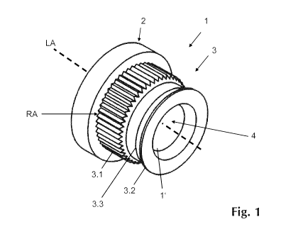
Fig. 1 shows a perspective view of a press-in connecting element
according to the
invention,
Fig. 2 shows an end-side view of the shaft section of the press-in
connecting element
according to the invention in accordance with figure 1,
Fig. 3 shows a longitudinal section along the line A-A through the
press-in connecting
element in accordance with figure 2,
Fig. 4 shows a schematic longitudinal section through an alternative
embodiment of a
press-in connecting element,
Fig. 5 shows a schematic longitudinal section through a press-in connecting
element
according to the invention which is inserted into a metal sheet and pressed
therewith, as well as the associated tools.
Figure 1 shows, by way of example, a perspective representation of a press-in
connecting element
1 according to the invention, which is designed as a press-in nut element with
internal thread in
the embodiment shown. Alternatively, however, the press-in connecting element
1 according to
the invention can also be produced as a press-in sleeve member without
internal thread. The
press-in connecting element 1 is made in one piece or integrally formed and is
produced from a
material or material mixture.
The press-in connecting element 1 is designed for inserting and anchoring into
a permanently
deformable flat metal material, in particular a metal sheet 10 or a component
or workpiece
produced therefrom, by joining and pressing, and for this purpose comprises a
sleeve-like main
5
CA 03059642 2019-10-10
KRI-0009-CA
body extending along a longitudinal axis LA, which main body comprises at
least a head section 2
and a shaft section 3, which directly adjoins the head section along the
longitudinal axis LA. The
shaft section 3 is formed by a substantially circular-cylindrical collar,
which has a reduced cross-
section in comparison to the head section 2, such that the head section 2
comes to abut against
the upper side of the metal plate in the inserted state. The head section 2 is
also preferably
produced in the form of a circular-cylindrical body section.
The sleeve-like main body further comprises a preferably circular-cylindrical
cavity 4, which is
enclosed by an inner wall 1' of the press-in connecting element 1 extending
concentrically toward
the longitudinal axis LA and extends over the entire length of the press-in
connecting element 1.
In the embodiment illustrated in the figures as a press-in nut element or
press-in nut, the inner
wall 1' is provided, by way of example, with an internal thread. The circular-
cylindrical cavity 4
extends in this case over the entire length of the press-in connecting element
1 and thus forms a
through bore for receiving and/or passing through a rod-shaped element, by way
of example the
shaft of a screw or bolt.
The press-in connecting element 1 is formed for pressing into a metal sheet 10
or into a
component or workpiece produced from a metal sheet 10, and it should be
anchored therein by
joining and pressing preferably with a high press-out force and torque
absorption. Figure 5 shows,
by way of example, a schematic longitudinal section through a press-in
connecting element 1
inserted into a metal sheet 10 and a longitudinal section through the
corresponding tools 12, 13.
In this case, the press-in connecting element 1 is preferably pressed into a
pre-punching 11,
inserted in the metal sheet 10, with the corresponding tools 12, 13 and
anchored therein. The
component or workpiece can, by way of example, be a component or workpiece
produced from a
steel sheet by punching and bending. Preferably, the material hardness of the
press-in connecting
element 1 is greater than the material hardness of the metal sheet 10.
The shaft section 3 comprises, by way of example, a joining section 3.1, which
directly adjoins the
head section 2 along the longitudinal axis LA, which joining section can be
adapted with respect to
its extent along the longitudinal axis LA depending on the material strength
of the metal sheet 10,
into which the press-in connecting element 1 according to the invention is
intended to be
anchored, and/or the respective application. The shaft section 3 further
comprises a press-in
section 3.2 on its free end opposite the head section 2, which press-in
section is preferably formed
by an annular press-in collar revolving concentrically around the longitudinal
axis LA. If there is no
pre-punching 11 in the metal sheet 10, the press-in section 3.2 can also form
an annular press-in
edge, by means of which a slug is punched out, in order to enable joining of
the subsequent
joining section 3.1.
6
CA 03059642 2019-10-10
KRI-0009-CA
The joining section 3.1 has a lateral surface having a knurl RA, in particular
a knurl RA having a
plurality of grooves running parallel to the longitudinal axis LA, which is
designated RAA knurl. As
a result, a serrated profile extending circumferential around the longitudinal
axis LA is produced on
the lateral surface of the joining section 3.1, wherein a groove is enclosed
in each case between
two consecutive serrations. The knurl RA has a knurl depth T.
The knurl RA illustrated or indicated in figures 1 to 5 is, by way of example,
formed as an RAA
knurl having a spacing t of 0.8 mm and a profile angle of 90 . It is evident
that RAA knurls with
different spacings t standardized according to DIN 82, by way of example 0.5
mm, 0.6 mm, 1.0
mm, 1.2 mm or 1.6 mm can also be used. Alternative profile angles are also
possible.
Before the knurl RA is formed in the lateral surface of the joining section
3.1, the latter has an
initial diameter D, which, depending on the selected spacing t, produces a
nominal diameter or
first diameter dl of the knurled joining section 3.1. The nominal diameter or
first diameter dl in
this case designates the diameter of a virtual circumference around the
longitudinal axis LA, on
which the outer tips of the knurl RA or serrations of the serrated profile
come to rest. In other
words: the first diameter dl designates the outer diameter of the knurled
joining section 3.1.
The knurl depth T corresponds to the difference of the radius of the virtual
circumference around
the longitudinal axis LA, on which the outer tips of the knurl RA or of the
serrations of the serrated
profile come to rest, and the radius of the further virtual circumference
around the longitudinal
axis LA, on which the inner tips of the knurl RA or of the serrations of the
serrated profile come to
rest.
In the case of an RAA knurl, by way of example, the following relationship
exists between the
initial diameter D of the still unknurled joining section 3.1, the nominal
diameter or first diameter
dl and the spacing t:
D = dl ¨ 0.5 * t
The knurl RA is in this respect preferably produced by turning. Alternatively,
the knurl RA can be
produced by cold working.
According to the invention, the knurled joining section 3.1 comprises the
first diameter dl and the
press-in section 3.2 a second diameter d2, wherein the second diameter d2 is
smaller than the
first diameter dl. In this context, the second diameter d2 corresponds
approximately to the initial
diameter D of the joining section 3.1 before the knurl RA is formed in the
lateral surface thereof, in
particular in the case of a knurl RA produced by turning, or the second
diameter d2 corresponds
approximately to the first diameter dl minus half of the knurl depth T, in
particular in the case of a
7
CA 03059642 2019-10-10
KRI-0009-CA
knurl RA produced by means of cold working. The second diameter d2 is thus
reduced by half of
the knurl depth R in comparison to the first diameter dl. The inventors have
discovered that in the
case of a respective dimensioning of the first and second diameter dl, d2 of
the knurled joining
section 3.1 and of the press-in section 3.2, there is no material displacement
when joining the
joining section 3.1 into the metal sheet 10, as advantageously the joining
region is already
correspondingly prepared over the press-in section 3.2.
According to the invention, the following relationship thus exists between the
first and second
diameter dl, d2 and the spacing t of the knurl RA formed as an RAA knurl:
d2 = dl - 0.5 * t
In the case of an RAA knurl having a spacing t of 0.8 mm and a profile angle
of 900, the following
relationship thus emerges, by way of example, between the first diameter dl of
the knurled joining
section 3.1 and the second diameter d2 of the press-in section 3.2:
d2 = d1 - 0.5 * 0.8 mm = dl - 0.4 mm
or
dl = d2 + 0.4 mm
The first diameter dl of the knurled joining section 3.1 is thus 0.4 mm larger
than the second
diameter d2, i.e. the difference of the first and second diameter dl, d2 is
selected depending on
the spacing t of the knurl RA. This applies in particular to an RAA knurl
produced by turning.
Alternatively, the following relationship exists between the first and second
diameter dl, d2 and
the knurl depth T of the knurl RA:
d2 = dl -0.5 *T
In the case of a knurl depth T of 0.8 mm, the following relationship thus
emerges, by way of
example, between the first diameter dl of the knurled joining section 3.1 and
the second diameter
d2 of the press-in section 3.2:
d2 = d1 - 0.5 * 0.8 mm = d1 - 0.4 mm
The first diameter dl of the knurled joining section 3.1 is in both cases 0.4
mm larger than the
second diameter d2, i.e. the difference of the first and second diameter dl,
d2 is selected
depending on the spacing t of the knurl RA or on the knurl depth T. This
applies in particular to an
RAA knurl produced by turning or cold working.
In one preferred embodiment, the head section 2 is likewise formed by a
circular-cylindrical
section, which has a head diameter dk and a head width bk respectively
relative to the longitudinal
8
CA 03059642 2019-10-10
KRI-0009-CA
axis LA. The preferably circular-cylindrical cavity 4 further has an inner
diameter di, which is
selected depending on the application, in particular depending on the size of
the internal thread to
be provided.
An annular undercut section 3.3 is arranged between the joining section 3.1
and the press-in
section 3.2, which undercut section forms a recess which is groove-shaped
and/or annular and
extends concentrically toward the longitudinal axis LA, in which recess the
material of the metal
sheet 10 is plastically deformed in the joining region when pressing the press-
in connecting
element 1 inserted into the metal sheet 10. The annular undercut section 3.3
can have different
cross-sectional shapes, by way of example form an undercut which is triangular
or trapezoidal in
the cross section. The annular undercut section 3.3 has thus a reduced cross-
section in
comparison to the joining section 3.1 and the press-in section 3.2 and thus
jumps back radially in
the direction of the longitudinal axis LA.
As a result of filling of the annular undercut section 3.3 with material of
the metal sheet 10, the
press-in connecting element 1 is additionally anchored in the metal sheet 10
alongside the knurl
RA of the joining section 3.1 and is secured in particular against twisting.
The knurled joining section 3.1 is formed by a knurled, circular-cylindrical
section which directly
adjoins the head section 2 along the longitudinal axis LA, which section has a
first width bl relative
to the extension along the longitudinal axis LA. The press-in section 3.2 is
provided on the
opposite free end of the shaft section 3, the second diameter b2 of said press-
in section being
relative to that outer circumferential surface or circumferential edge of the
press-in section 3.2,
which has the greatest radial distance to the longitudinal axis LA. This press-
in section 3.2 is, by
way of example, formed by an annular press-in collar, the greatest outer
diameter of which forms
the second diameter d2. Preferably, the end face of the press-in section 3.2
of the shaft section 3
forms a flat annular surface, which is concentric with respect to the
longitudinal axis LA.
Finally, the annular undercut section 3.3. comprises a third diameter d3,
preferably in the region
of the circumferential surface with the lowest radial distance to the
longitudinal axis LA. The third
diameter d3 of the annular undercut section 3.3 is smaller than the first and
second diameter dl,
d2. The difference between the second and third diameter d2, d3 is preferably
selected in the
region of between 0.25 times and one times the spacing t of the knurl RA of
the knurled joining
section 3.1 formed as an RAA knurl.
In the present exemplary embodiment in accordance with figures 1 to 3, the
annular undercut
section 3.3 is formed by a circular-cylindrical section extending
circumferentially and concentrically
around the longitudinal axis LA and having a third width b3, which section
merges into the joining
9
CA 03059642 2019-10-10
KRI-0009-CA
section 3.1 or the press-in section 3.2, widening the cross section, via in
each case a transition
section extending obliquely to the longitudinal axis LA.
In a further alternative embodiment in accordance with figures 4 and 5, the
annular undercut
section 3.3 comprises an arcuate cross-sectional profile, such that the third
width b3 is reduced
substantially to an apex line having the smallest radial distance to the
longitudinal axis LA.
In further embodiment variants (not illustrated), the annular undercut section
3.3 can comprise a
triangular cross-sectional profile, wherein this annular undercut section 3.3
opens outward in the
form of a gap or the receiving space formed thereby tapers in the direction of
the longitudinal axis
LA.
Figure 5 shows, by way of example, in a schematic side view the tools, in
particular press tools,
provided for inserting the press-in connecting element 1 into the metal sheet
10 or into a pre-
punching 11 provided by way of example, by joining and pressing. The diameter
of the pre-
punching 11 is preferably selected to be marginally smaller than or the same
as the second
diameter d2 of the press-in section 3.2 or the outer diameter D of the joining
section 3.1 before
the knurl RA is formed. Alternatively, a corresponding slug can firstly be
punched out of the metal
sheet by means of the press-in section 3.2 and the tools 12, 13, which enables
subsequent joining
of the joining section 3.1 in the tool.
In order to attach the press-in connecting element 1 to the metal sheet 10,
the press-in
connecting element 1 is inserted with deformation of the material of the metal
sheet 10 around, by
way of example, the previously punched-out joining opening or pre-punching 11,
in such a manner
that the material flows radially into the grooves, running parallel to the
longitudinal axis LA, of the
knurl RA, nevertheless preventing an axial displacement of the material in the
joining direction, i.e.
along the longitudinal axis LA. After joining, the head section 2 with its
lower side facing towards
the joining section 3.1 bears against the upper side 10a of the metal sheet,
wherein the remaining
shaft section 3 is preferably completely received in the pre-punching 11 and,
by way of example,
flush or approximately flush with the lower side 10b of the metal sheet 10.
The shaft section 3 can
also project with its free end, and with the press-in section 3.2 over the
lower side 10b of the
metal sheet 10.
Subsequently, in a press or a press tool with the head section 2 supported
against a support 12,
.. using a die 13 having an annular embossing collar 14, plastic deformation
takes place of the
material of the metal sheet 10 into the recess, which is groove-shaped and/or
annular by way of
example and extends concentrically around the longitudinal axis LA and is
formed by the annular
CA 03059642 2019-10-10
KRI-0009-CA
undercut section 3.3. In the case of a stationary die 13, the support 12 is
formed by way of
example by a pressing punch or pressing plunger.
In order to anchor the press-in connecting element 1 in the joining opening or
pre-punching 11,
the die 13, which encloses or fully receives the press-in section 3.2 or press-
in collar when
pressing with its embossing collar 14, almost exclusively exerts force on the
material of the metal
sheet 10 in such a manner that primarily a flow of the material of the metal
sheet 10 is brought
about without deforming the press-in connecting element 1 for the anchoring or
pressing of the
press-in connecting element 1 in the metal sheet 10. The transmission of force
takes place in this
.. context exclusively over the embossing collar 14 in the direction of the
longitudinal axis LA.
Figure 5 thus shows, by way of example, a prefabricated assembly comprising a
press-in
connecting element 1 according to the invention and a metal sheet 10, wherein
the press-in
connecting element 1 is inserted into the metal sheet 10 indicated by way of
example, by joining
and pressing. It is understood that the metal sheet 10 indicated can also be
part of a component
or workpiece produced therefrom, without hereby departing from the inventive
concept.
With the method described previously, anchoring of the press-in connecting
element 1 with high
press-out force or high press-out strength and with a high torque, i.e. with
high resistance to
twisting, is achieved. After the anchoring of the press-in connecting element
1 in the metal sheet
10 has been completed, the annular undercut section 3.3 bears in its entire
profile, in particular
also in the region of the transitions to the joining section 3.1 and/or press-
in section 3.2 with a
high pressing or clamping force against the peripheral region, which surrounds
the joining opening
or pre-punching 11, of the metal sheet 10.
The invention has been described above using exemplary embodiments. It is
understood, that
numerous changes and modifications are possible, without hereby departing from
the inventive
concept upon which the invention is based.
11
CA 03059642 2019-10-10
KRI-0009-CA
Reference list
,
1 press-in connecting element
1' inner wall
2 head section
3 shaft section
3.1 joining section
3.2 press-in section
3.3 undercut section
4 cavity
10 metal sheet
10a upper side
10b lower side
11 pre-punching
12 support
13 die
14 embossing collar
bl first width
b2 second width
b3 third width
bk head width
dl first diameter
d2 second diameter
d3 third diameter
dk head diameter
di inner diameter
LA longitudinal axis
RA knurl
t spacing
T knurl depth
12