Note: Descriptions are shown in the official language in which they were submitted.
CA 03059868 2019-10-11
WO 2018/191158 PCT/US2018/026697
TWO-MATERIAL P&A PLUG
PRIOR RELATED APPLICATIONS
[0001]
This invention claims priority to US Provisional App. No. 62/484,624, filed on
April 12, 2017 and incorporated by reference in its entirety herein for all
purposes.
FIELD OF THE DISCLOSURE
[0002]
The disclosure relates to plug and abandonment operations, and specifically to
a two-material plug that has multiple sealing mechanisms and improved
structural
integrity over the use of either material alone.
BACKGROUND OF THE DISCLOSURE
[0003] There are several thousand active oil and gas wells located around
the world,
with thousands more to come on-stream in the next ten years. The wells differ
in
design, size, cost and economic benefit. The wells have one thing in common:
sooner
or later they will be decommissioned and abandoned.
[0004]
The decision to plug and abandon (P&A) a well or field is invariably based on
economics. Once production delivers less than the operating expenses, it is
time to
consider abandonment. In some situations, the decision is made with the
knowledge
that considerable reserves remain, but the cost to extract these resources is
more than
the projected income.
[0005]
There are regulatory requirements associated with the P&A process to ensure
that strata, particularly freshwater aquifers, are adequately isolated. The
plug's length,
cross-section, position and verification tests are typically regulated and
depend on the
type and location of the well being plugged. Thus, the cost to P&A a well can
vary by
many millions of dollars depending on location, and whether the well is
offshore or
onshore. Minimizing costs, without sacrificing well integrity, is critical to
operators,
1
CA 03059868 2019-10-11
WO 2018/191158
PCT/US2018/026697
who make a significant investment with no financial return in the case of P&A
operations.
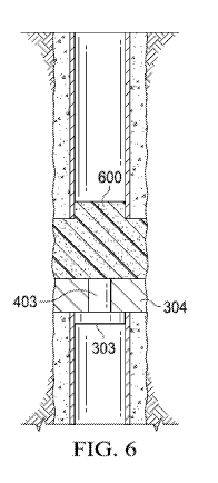
[0006]
FIG. 1 displays a simple schematic of a basic plug. A modern requirement for
a permanent well barrier is that it must include all annuli, extending to the
full cross
section of the well and seal both vertically and horizontally. In FIG. 1, a
cement plug
(104) is sealing vertically inside the casing and sealing both horizontally
and
vertically in the casing-formation annulus (102) above the casing shoe (103).
However, cement is easily contaminated with mud, which results in placement
issues
and often resulting in plug failure.
[0007] Because cement is susceptible to failure if contaminated by drilling
or other
fluids, and long length cement plugs are required, other materials have been
investigated for use as plugging material. Resins seal by adhesion, and have
resistance to many caustic and corrosive chemicals, excellent mechanical
properties,
such as high strength and high shear, and flexibility and toughness after
setting.
However, resin plugs can be more difficult to set successfully because of the
relatively complex chemistry and the need for time to cure. Further, resin
plugs will
fall down the well bore and annulus unless the bore and annulus are plugged.
They
must be set on a base and the annulus sealed. Shrinkage of the resin can also
occur as
it cures unless formulated correctly and can lead to micro-annuli and cracks
in the
sealant and/or lack of bonding of the seal, plug or connection to its
surroundings.
[0008]
Although cement and resin are the most common plug materials,
improvements in plug composition and methods are desired to reduce costs. One
alternative is to "cast-in-place" a metal plug. A eutectic alloy, such as an
expandable
bismuth alloy, is heated in place to form a molten liquid metal that easily
penetrates
small crevices and cracks, and hardens in place forming a tight plug. The
specific
gravity of the metal being much higher than any fluid, results in effective
placement.
A heater tool, described in W02011151271 and W02014096858, is commercially
available from BiSN Oil Tools, and can heat such cast-in place bismuth alloy
plugs.
The BiSN Wel-lok M2M Bridge PlugTM can run on standard wireline, slick line or
coil tubing. It uses a bismuth-based alloy that is melted in situ by a
chemical reaction
2
CA 03059868 2019-10-11
WO 2018/191158 PCT/US2018/026697
heater that uses materials, such as thermite, to generate heat. However, this
tool can
only heat a limited volume of alloy at a time, and thus other methods and
tools are
still needed for P&A.
[0009]
Thus, there still exists a need to improve plug formation in P&A operations
while also decreasing cost and time. Ideally, the new plugs would be safe,
create a
reliable barrier, be cost effective, and both faster and easier to perform
than current
methods.
SUMMARY OF THE DISCLOSURE
[0010]
Described herein is a new plug and method for plug and abandonment
operations. Specifically, the new plug combines resin and a eutectic alloy to
provide
two redundant sealing mechanisms. This results in a shorter plug being needed
for an
improved sealing. Methods of installing the plug are also described.
[0011]
Plugging and abandonment (P&A) regulations vary among states and between
countries, but all regulations prescribe the depth intervals that must be
plugged, as
well as the materials that are allowed in plugging practices. For instance, in
the North
Sea, current P&A guidelines require plugs between 30 to 50 meters in length.
To set
such plugs, the wellbores undergo section milling, or perforation, wash and
cement
(PWC) processes. Both operations require substantial amounts of time and
exorbitant
cost. Further, milling or perforating 30-50 meters is not always economical or
feasible, especially where the area to be plugged has multiple strings of
casing that
need to be removed.
[0012]
Shorter plugs would require less casing being removed and reduce costs. One
proposal for reducing the size of plugs is to utilize more than one material
for the
plug. For example, one option that has been presented is the use of two-
material plugs
using cement and resin. Generally, these plugs consist of a base plug, annulus
seal, a
resin layer, and then a cement layer. However, the resin requires time to set
before the
cement can be placed, thus delaying the plugging operation. Further, the
cement is
used just to hold the resin in place and is not a rock-to-rock plug of the
formation. The
3
CA 03059868 2019-10-11
WO 2018/191158 PCT/US2018/026697
problem with this plug is the time to set, including the based plug and
annulus seal. If
the annulus or base is not sealed correctly, all the resin could fall down the
well bore
or annulus as the resin will have a higher specific gravity than the fluid in
the well.
[0013]
In response to the long-felt need for better plugs that are smaller and more
economical to place, Applicant has developed a two-material plug that
overcomes the
problems associated with the resin/cement plug. Specifically, the currently
described
plug utilizes eutectic alloy-based material and resin to form the seals. The
eutectic
alloy material, preferably bismuth-based, is added to the wellbore first,
where it
undergoes a heating step to melt the alloy, allowing it to expand and form a
"cast-in-
place" metal seal. This alloy plug acts as a base for the resin while sealing
the annulus
and wellbore with a rock-to-rock plug. This metal seal, along with the sleeve
or frame
of the heater used to melt the alloy, provides a structural component for the
resin to
attach thereto. The resin is the second layer to be added and it too forms a
rock-to-
rock seal that is cast-in-place across the wellbore as well as sealing the
heater frame.
[0014] The order of the materials used in the plug is important. The
bismuth-based
alloy is immiscible with fluids in the wellbore and is corrosive resistant.
Thus, no
long-term failure due to fluid contact is expected. By placing the resin above
the
metal seal, the resin, which can also be immiscible in the fluids, is
protected from
hydrocarbon contact that can negatively affect the resin. As such, the alloy
forms the
base and seals the annuli. Further, the flexural failure of the resin section
is reduced
through the use of the metal plug, and the heater sleeve and its components,
as
reinforcement. This is analogous to steel reinforcement in concrete.
[0015]
The described plug has a wide potential use in plugging operations, and can be
used in all offshore producing areas. Further, smaller openings needed for
accessing
the annular space. The described plug is expected to decrease abandonment
costs by
25% or more for wells that have two strings of casing across the area to be
plugged.
[0016]
This new plug has many advantages over currently used plugs and other
proposed two-material plugs. First, the two materials use different sealing
mechanisms. The eutectic alloy seals by expansion and the resin seals by
adhering to
4
CA 03059868 2019-10-11
WO 2018/191158 PCT/US2018/026697
a surface. This reduces the probability of plug failure because either of the
materials
can plug the wellbore on its own and has different properties and thus
differential
failure rates under the same conditions. Further, the eutectic alloy layer
acts as a
plug, annulus seal, and base for which the resin can be placed. This not only
gives the
resin something to adhere to, but the metal seal prevents the resin from
running down
the sides of the wellbore or from contacting reservoir fluids. The metal plug
and
various components such as the heater sleeve also reinforce the resin. In
large
diameter wellbores, flexural failure of resin plugs is a concern. However,
with the
metal plug and its components above in the center of the wellbore, the
effective
diameter of the resin plug is reduced. The resin adheres to the components in
the
center of the casing. Finally, both materials are immiscible with the water-
based
fluids in the reservoirs or fluids used during P&A operations.
[0017]
The eutectic alloy is preferably a bismuth-based alloy. Bismuth alloys are a
preferred cast-in-place abandonment plug material because bismuth expands 1-
3.32%
on solidification. Bismuth also has unusually low toxicity for a heavy metal.
Furthermore, Applicant has tested these alloys and determined that the liquid
alloy
does not mix with other fluids, like cement does. Thus, the channeling common
in
cement plugs is avoided.
[0018]
Exemplary bismuth-based alloys are described in US7290609. As a general
rule, bismuth alloys of approximately 50% bismuth exhibit little change of
volume
(1%) during solidification. Alloys containing more than this tend to expand
during
solidification and those containing less tend to shrink during solidification.
Additional
alloys are described in US20150368542, which describes a bismuth alloy
comprises
bismuth and germanium and/or copper. Preferably, the bismuth-based alloy is
eutectic. Additional eutectic alloys to plug wells or repair existing plugs in
wells are
described in US7152657; US20060144591; US6828531; US6664522; US6474414;
and US20050109511.
[0019]
U. S . Serial No. 62/402,796, filed September 20, 2016, and incorporated
herein
in its entirety for all purposes, also describes bismuth alloy abandonment
plugs and
5
CA 03059868 2019-10-11
WO 2018/191158 PCT/US2018/026697
methods of setting them. In some embodiments, the bismuth alloys are preferred
due
to their low melt temperatures, ease of use and robustness.
[0020]
A low-melting point bismuth-containing alloy such as "Rose's metal", "Kraft's
alloy" or "Homberg's alloy", or any other suitable bismuth alloy is used. Such
alloys
are unusual in that they have a higher density in liquid form than in their
solid state
and therefore expand upon solidification. Once deposited in a well they lose
heat into
the surrounding environment, solidify, and expand to form a very secure plug
within
the well. Furthermore, there are commercially available tools and prototype
tools are
being developed that can heat bismuth alloy pellets downhole, such as the Wel-
Lok,
thus allowing the use of these materials as cast-in-place abandonment plugs,
but with
no nonmetal components that could deteriorate.
[0021]
The resin can be any resin typically used in P&A operations. Thermosetting
resins have been used in wells (oil, gas, water or even waste disposal wells)
before.
Those having a thermal expansion coefficient significantly greater than 10-3
vol % per
C may in principle be used, as long as shrinkage occurring during curing is
compensated for. Also, mixtures of resins may be used in the presently
described
plug.
[0022]
Resin sealing materials include ThermaSet by Wellcem AS, CannSeal by
AGR, and the WellLock resin system by Halliburton. M&D Industries also makes
resin plugging materials, including LIQUID BRIDGE PLUG with a range of
hardeners and accelerators. The WellLock resin, for example, uses cross-
linking
between an amine hardener and epoxides, resulting in a cured three-dimensional
infinite polymer network, and can be deployed without negative impact from
exothermic reactions triggered by water.
[0023] A two-material total plug length of less than 15 meters, each
portion being less
than 5 meters, preferably less than 2 meters, will provide the same protection
as the
typically 30-50 meter cement plugs. The two-material plug has two different
sealing
mechanisms, both materials being immiscible with P&A work fluids (low level
contamination), and both can use gravity segregation for placement. Their
6
CA 03059868 2019-10-11
WO 2018/191158 PCT/US2018/026697
complimentary properties and different sealing mechanisms make them as
effective as
longer cement plugs.
[0024]
In forming the metal seal, a tool that includes storage for the alloy as
either
pellets or a layered metal, a heater, a sleeve or frame for holding and
protecting the
heater, and a base or canister in which the alloy is stored will be needed to
place at
least the first load of alloy. The sleeve or frame protects the heater from
damage as it
is lowered downhole and prevents direct contact with the alloy, which could
potentially solidify therewith and prevent the heater from being retrieved.
Once the
heating is finished, the heater can be removed, leaving an open sleeve with
additional
attachment points for the resin.
[0025]
A base plug can be used for setting the metal plug, or the components of the
heater can provide a base that is retained in the plug on removal of the
heater portion.
However, the base may be optional, as these alloys tend to not travel very far
before
they cool and harden, thus providing their own base.
[0026] Multiple additions of alloy pellets may be needed to build the
appropriate
amount or height of alloy. Thus, the first load of alloy can be placed by the
tool, such
that the alloy will be heated, and then cooled into the seal. A second, third,
or more
load of alloy can then be placed using an e.g. dump bailer. The top of the
open sleeve
can be plugged with a "dummy" heater, or cap, while dumping the alloy. The
"dummy" heater would then be pulled to allow for placement of a thermite-
containing
heater. The thermite-containing heater is ignited to heat the additional loads
of alloy
to grow the height of the metal plug.
[0027]
Once the metal alloy has been placed, the heater is removed (leaving the
sleeve behind) and the resin is added on top of the metal seal and heater
sleeve. The
resin attached and adheres to the metal seal and the frame or sleeve that
housed the
heater. It is expected that the top of the tool can be removed once the
initial metal seal
is set, allowing for the removal of the heater, and opening up of the heater
sleeve and
base for resin attachment.
7
CA 03059868 2019-10-11
WO 2018/191158 PCT/US2018/026697
[0028]
For placing the plug rock-to-rock, parts of the wellbore must be removed to
allow annular access. This can be accomplished using section milling or
perforation/wash operations. However, a smaller section of opening(s) is
needed
because the plug will be shorter than the traditional all cement or all resin
plugs.
However, any method of removing the strings is acceptable, including various
means
of cutting the casings and other tubulars, and/or specific design of cuts or
removal of
the strings.
[0029]
Both layers of the two-material plug are expected to expand to fill the
openings in the casing and form a rock-to rock (i.e. the seal contacts the
formation
rock). However, in some embodiments, some end or terminal portions of the plug
may not be rock-to-rock.
[0030]
This summary is provided to introduce a selection of concepts that are further
described below in the detailed description. This summary is not intended to
identify
key or essential features of the claimed subject matter, nor is it intended to
be used as
an aid in limiting the scope of the claimed subject matter.
[0031]
As used herein, a "P&A" refers to plug and abandon. Regulations require that
the plugs be of sufficient quality to be "permanent," never allowing formation
fluids
to leak. However, it is recognized that even a permanently plugged and
abandoned
well may be reopened at a later time for various reasons. Therefore,
"permanent"
does not imply that the well will not be reopened, but instead refers to the
quality of
the plug¨it needing the potential to last permanently. That said, most plugs
probably
won't last forever, and some degree of flexibility in meaning can be
accommodated by
these terms of art.
[0032]
The most effective way to prevent hydrocarbon migration in wells that have
been plugged and abandoned is to create a "rock-to-rock" seal. This means the
seal
reaches to the formation walls.
[0033]
As used herein, "casing string" and "string" are used interchangeable to refer
to a long section of connected oilfield pipe that is lowered into a wellbore
and
cemented. Often, multiple strings of concentric casings are used in a
wellbore.
8
CA 03059868 2019-10-11
WO 2018/191158 PCT/US2018/026697
[0034] As used herein, "dump bailer" refers to a wireline or
slickline tool used to
place small volumes of cement slurry, or similar material, in a wellbore.
[0035] The expression "resin" refers to "classic" thermosetting
resins, as well as
ductile, vulcanizable rubbers. The cured resin is expanded to at least the
volume
occupied by the resin prior to curing to compensate for shrinkage.
[0036] A "Perforation" tool makes a plurality of discreet holes of
roughly equal size
and even distribution, leaving the tubing otherwise intact.
[0037] The term "cast-in-place" refers to the formation of a seal in
situ in the
wellb ore.
[0038] The use of the word "a" or "an" when used in conjunction with the
term
"comprising" in the claims or the specification means one or more than one,
unless
the context dictates otherwise.
[0039] The term "about" means the stated value plus or minus the
margin of error of
measurement or plus or minus 10% if no method of measurement is indicated.
[0040] The use of the term "or" in the claims is used to mean "and/or"
unless
explicitly indicated to refer to alternatives only or if the alternatives are
mutually
exclusive.
[0041] The terms "comprise", "have", "include" and "contain" (and
their variants) are
open-ended linking verbs and allow the addition of other elements when used in
a
claim.
[0042] The phrase "consisting of' is closed, and excludes all
additional elements.
[0043] The phrase "consisting essentially of' excludes additional
material elements,
but allows the inclusions of non-material elements that do not substantially
change the
nature of the invention.
[0044] The following abbreviations are used herein:
ABBREVIATION TERM
9
CA 03059868 2019-10-11
WO 2018/191158 PCT/US2018/026697
P&A Plug and abandonment
PWC perforation/wash/clean
BRIEF DESCRIPTION OF THE DRAWINGS
[0045] FIG. 1. Schematic of a traditional cement plug in a wellbore.
[0046] FIG. 2. Depiction of a wellbore in its initial state and after
portions thereof are
removed for plug placement using section milling, perforation, or
perforation/wash
techniques.
[0047] FIG. 3A. A section of milled wellbore having a Wel-LokTm tool
with alloy
metal. FIG. 3B is the same well after the alloy metal has been heated and
cooled to
form a rock-to-rock seal.
[0048] FIG. 4. Removal of heater per one embodiment of the present
description.
[0049] FIG. 5. Place of resin on top of metal seal.
[0050] FIG. 6. Two-material plug per one embodiment of the present
description.
DESCRIPTION OF EMBODIMENTS OF THE DISCLOSURE
[0051] The invention provides a novel plug for wellbore plug and
abandonment
operations. This novel plug utilizes a eutectic alloy and a resin to form a
two-
component plug. Because each material seals the wellbore using different
mechanisms, there is a redundancy in the seals. This allows for a smaller
amount of
materials to accomplish the same level of sealing as traditional plugs, and a
smaller
amount of tubular will need to be removed. The combined two-material plug has
greater integrity under wellbore conditions than a similar total length plug
of either
material alone.
[0052] The present methods includes any of the following embodiments
in any
combination(s) of one or more thereof:
CA 03059868 2019-10-11
WO 2018/191158
PCT/US2018/026697
A method of plugging a well during plug and abandonment operations
comprising:
a) deploying a first tool downhole to remove or perforate both an inner
tubular and/or exterior casing at a section of well to be plugged;
b) deploying a second tool downhole, said second tool having a eutectic
alloy in a storage space, a sleeve for holding a heater and an optional base;
c) deploying a heater downhole in said sleeve;
d) heating said eutectic alloy with said heater to form a molten alloy;
e) allowing said molten alloy to expand and solidify to form a cast-in-
place
metal plug that fills at least part of said section of well to be plugged and
seal the
annulus;
removing said heater, but not said sleeve;
deploying a resin downhole on top of said metal plug;
h) curing said resin, wherein said cured resin adheres to and covers said
cast-in-place metal plug and said sleeve; and
i) wherein said cast-in-place metal plug and said cast-in-place resin plug
form a single two-material plug.
A method of plugging a well during plug and abandonment operations
comprising:
a) removing or perforating or opening both an inner tubular and an exterior
casing at a section of well to be plugged;
b) optionally deploying a base plug at or near said section;
c) deploying a eutectic alloy downhole on top of said base plug or at said
section;
d) heating said eutectic alloy to form a molten alloy;
e) allowing said molten alloy to expand and solidify to form a cast-in-
place
metal plug that fills at least part of said section of well to be plugged;
removing said heater;
deploying a resin downhole on top of said cast-in-place metal plug; and,
h) curing said resin to form a resin plug, wherein said resin plug
and said
cast-in-place metal plug form a single two-material plug that is a rock-to-
rock
plug.
11
CA 03059868 2019-10-11
WO 2018/191158
PCT/US2018/026697
A method of plugging a well during plug and abandonment operations
comprising:
a) deploying a first tool downhole to remove or perforate both an inner
tubular and exterior casing at a section of well to be plugged;
b) deploying a second tool downhole having a base, a sleeve erected
therefrom for holding a heater, a heater and an alloy, wherein said alloy is
stored
above said base and around said sleeve;
c) heating said eutectic alloy with said heater to form a molten alloy;
d) allowing said molten alloy to expand and solidify to form a cast-in-
place
metal plug that fills at least part of said section of well to be plugged;
e) adding additional eutectic alloy to said well and repeating steps c-d
until
a predetermined height of cast-in-place metal plug is formed;
removing said heater but not said sleeve;
deploying or pouring a resin downhole on top of said cast-in-place metal
plug;
h) curing said resin to form a resin plug, wherein said cured resin adheres
to
said cast-in-place metal plug, further wherein the cure resin covers said cast-
in-
place metal plug and said sleeve of said second tool; and
i) wherein said cast-in-place metal plug and said resin plug form a single
two-material plug that is a rock-to-rock plug.
Any method herein, further comprising evaluating the seal of said single two-
material plug.
Any method herein, wherein said first tool performs section milling.
Any method herein, wherein said first tool performs perforation and wash
operations.
Any method herein, wherein said first tool opens and expands said inner
tubular
and exterior casing.
Any method herein, wherein said eutectic alloy comprises bismuth.
Any method herein, wherein said resin is a thermosetting resin, a vulcanizable
rubber or combinations thereof
Any method herein, wherein said second tool is a Wel-lok tool.
Any method herein, wherein additional alloy is added to said wellbore and the
hating and solidfying steps are repeated.
Any method herein, wherein said plug is less than 15 meters.
Any method herein, wherein said cast-in-place metal plug is less than 5
meters.
Any method herein, wherein said cast-in-place metal plug is less than 2
meters.
Any method herein, wherein said rock-to-rock plug is less than 5 meters.
Any method herein, wherein said two-material plug has enhanced integrity when
compared to an equivalent total length of either material alone.
Any method herein, wherein said method requires less time than a method using
a two material plug comprising resin and cement.
A method of P&A, wherein said method deploys a P&A plug that has two
materials being complementary in sealing processes, one material being an
expansion metal and one material being an adhesion resin.
Any method herein, wherein deploying said P&A plug that requires less time
than two material plug comprising resin and cement.
12
CA 03059868 2019-10-11
WO 2018/191158 PCT/US2018/026697
Any method herein, wherein said two material plug has enhanced integrity when
compared to either material alone.
Any two material plug herein, wherein the plug has an eutectic alloy base
layer
and a resin layer above and in physical contact with the eutectic alloy base
layer.
Any two material plug herein, wherein the eutectic alloy base layer is bismuth
and/or the resin layer is a thermosetting resin, a vulcanizable rubber or
combinations thereof
[0053]
The present invention is exemplified with respect to the description below and
FIG. 2-6. However, this is exemplary only, and the invention can be broadly
applied
to any wellbore that is being abandoned. The following examples are intended
to be
illustrative only, and not unduly limit the scope of the appended claims.
[0054] The first step in plugging a wellbore is to create access to the
annulus by
cutting through the strings. FIG. 2 displays wellbores that has been modified
by the
most commonly used methods to contrasts these methods with a wellbore in its
initial
state (200). The most commonly used options to access the annulus are section
milling (201), wherein an entire section of the casing string is removed; slot
perforation (202), wherein slots are cut into the casing string over; and
perforation/wash (203), wherein slots are cut into the casing string and a
circulated
fluid cleans the annular space to remove debris from the perforations.
[0055]
Annular access allows for placement of rock-to-rock seals using the alloy
and/or resin. While each of the commonly used techniques to gain access has
its own
advantages or disadvantages, any method of opening access to the annulus can
be
used with the described plug. For instance, Ser. No. 62/470,234, filed March
11,
2017, describes a technique that cuts helical coils into the strings to create
openings in
the casing that will aid in the formation of multiple o-ring type mini-seals
as the
material expands into the opening.
[0056] Once the strings are cut or milled, operations to set the plug
material can
proceed. The section of the wellbore that is milled or perforated is called a
"window."
The eutectic alloy, preferably a bismuth-based alloy, is placed at the bottom
of the
window and heated. The alloy is inert, environmentally friendly and is not
affected by
corrosion, hydrogen sulfide or acidic attack. A base plug may be needed to
support
13
CA 03059868 2019-10-11
WO 2018/191158 PCT/US2018/026697
the molten alloy in some embodiments, but in other embodiments, a tool is used
that
provides its own base, or the base is omitted and the molten alloy forms its
own base.
[0057]
Though this plug is being described as being set in a wellbore with an
intentionally opened annulus, the bismuth-based alloy can also be set in
undamaged,
damaged or corroded casing due to the molten alloy flowing into any profile or
shape.
[0058]
The metal alloy plug must be placed first because its acts as a base of
support,
seals the annuli, and an attachment point for the resin. Any wellbore tool,
such as a
dump bailer, with the ability to place pellets or sheets of the alloy can be
used.
Depending on the chosen tool, a base plate may have to be installed at or
below the
bottom of the window to prevent the molten alloy and/or alloy pellets from
draining
down the wellbore. The base plug need not be perfect, and may be omittable,
because
the alloy will flow a fairly limited distance before solidifying sealing the
well bore
and annulus. Any known base plate and methods of installation can be used.
[0059]
Preferably, the alloy is placed using a Wel-lokTm tool from BiSN Oil Tools.
The Wel-lokTm tool is preferred over other tools because it has a storage
space for
alloy layers (302) and a heater (301) in a sleeve, as shown in FIG. 3A.
Further, the
bottom of the Wel-lokTm tool can act as a cooling shelf (303) for the molten
alloy to
solidify (304) upon after it flows out of the storage space, as shown in FIG.
3B.
[0060]
The Wel-lokTm tools have a bismuth-based alloy that is melted in situ using a
chemical reaction heater. The molten alloy is then able to flow from its
storage space
on the tool and expand into the annulus space towards the formation. As
mentioned
above, the bottom of the Wel-lokTm tool has a shelf which will be several
degrees
cooler than the molten alloy and can act as a cool area to slow the flow of
the heated
alloy so that it is not lost down the well, but instead cools in the target
region.
[0061] If more bismuth-based alloy is need to adjust the height of the
metal seal, it
can be added using a dump bailer or other tool. The sleeve can be temporarily
plugged with a "dummy" heater or some other blocking device during the
addition of
new alloy, then removed as needed for placement of the actual heater (301) in
the
sleeve. As before, a heater (301) is placed in the sleeve to heat the new
alloy. As the
14
CA 03059868 2019-10-11
WO 2018/191158 PCT/US2018/026697
metal seal is created, the frame or sleeve encompassing the heater will become
part of
the seal and provide an additional surface for the resin to adhere.
[0062]
The top (401) of the Wel-lokTm (400) or similar tool should be removable to
pull the heater (402) out of its sleeve (403), per FIG. 4. The top (401) can
be removed
by shearing it off or melting pins that were used to keep the top and heater
in place.
For instance, the top can be removed using a charger or cutter. Removing the
heater
would open the sleeve or frame and allow for the resin (501) to be placed in
the open
frame, per FIG. 5. The added surface area of the open sleeve or frame leads to
more
attachment points for the resin to adhere. Enough resin, however, is needed to
fully
cover the sleeve or frame to prevent any imperfections or open pockets in the
resin
seal.
[0063]
In evaluating the plug, the metal alloy portion can be pressure tested within
hours, which provides significant costs savings when compared to cement or
resin,
which can require one or more days to set. Because true metal-to-metal and
metal-to-
wall seals are made, a permanent gas/liquid tight seal is created for any oil
well
abandonment.
[0064]
If the metal alloy portion of the plug is found to have created a useable
seal,
then the resin can be added to the top of the metal seal and frame using a
dump bailer
(502), poured from the surface and fall through the P&A fluid to the metal
alloy plug,
(503) or placed with pipe, tubing, or coil tubing (504). The resin will flow
through the
frame from the heater and flow out towards the formation. As the resin is
immiscible
and typically has a specific gravity higher than fluid in the well bore it
will fall and
displace the fluid on top of the metal plug.
[0065]
Access to the annulus can be obtained by methods outlined previously, section
milling, perforation, PWC, or expansion and opening, and combinations thereof
The
plug placement process is basically the same for these methods. There may be
variations in volume of metal alloy and resin. For example, PWC might require
a
longer metal plug to insure the annulus is sealed because alloy must flow
through
CA 03059868 2019-10-11
WO 2018/191158 PCT/US2018/026697
perforations to seal the annulus. If a well is just perforated, then a longer
resin plug
may be placed and squeezed into the perforations.
[0066]
Enough resin is needed to plug the remaining open space in the casing strings
and cover the top of the heater sleeve while compensating for shrinkage that
occurs as
the resin cures, as the final resin plug (600) is exemplified in FIG. 6.
[0067]
Shrinkage is a potential issue that has to be addressed in resin-only plugs,
but
is less of an issue with the cast-in-place eutectic alloy base plug
thereunder. The resin
can be squeezed slightly against the metal base plug to insure adhesion to the
well
bore surfaces. This squeezing will compensate for shrinkage as it will enhance
adhesion ensuring gas tightness of the well. With the metal bottom layer that
forms a
rock-to-rock seal, shrinking of resin in the present invention does not lead
to plug
failure as adhesion can be enhanced. .
[0068]
The traditional tests to confirm plug integrity can be used in evaluating the
installed plug positive pressure tests and negative pressure tests, inflow
tests, and the
like. If logging is desired the plug could be drilled out and logged. The
resin could
contain a tracer of some sort for logging. However, generally cement P&A plugs
are
not drilled out, and logged with pressure and tagging tests being the most
common
method of testing plugs.
[0069]
Once in place and sufficiently sealing the wellbore, the remaining
abandonment operations can proceed as normal.
[0070] The following references are incorporated by reference in
their entirety.
[0071]
U520060144591 Method and apparatus for repair of wells utilizing meltable
repair materials and exothermic reactants as heating agents
[0072]
US20100006289 Method and apparatus for sealing abandoned oil and gas
wells
[0073]
U520130333890 Methods of removing a wellbore isolation device using a
eutectic composition
16
CA 03059868 2019-10-11
WO 2018/191158 PCT/US2018/026697
[0074] US20130087335, Method and apparatus for use in well
abandonment
[0075] US20150345248, US20150368542, US20160145962, Apparatus for use
in
well abandonment
[0076] US20150368542 Heat sources and alloys for us in down-hole
applications
[0077] US6474414 Plug for tubulars
[0078] US6664522 Method and apparatus for sealing multiple casings
for oil and gas
wells
[0079] US6828531 Oil and gas well alloy squeezing method and
apparatus
[0080] US6923263 Well sealing method and apparatus
[0081] US7152657 In-situ casting of well equipment
[0082] US7290609, Subterranean well secondary plugging tool for
repair of a first
plug
[0083] US20150053405 One trip perforating and washing tool for
plugging and
abandoning wells
[0084] COP 42455, U.S. Serial No. 62/402,821, September 30, 2016.
[0085] COP 42425, US Serial No. 62/402,810, September 30, 2016.
[0086] COP 42423, US Serial No. 62/402,802, September 30, 2016.
[0087] COP 42472, US Serial No. 62/470,234, filed March 11, 2017
17