Note: Descriptions are shown in the official language in which they were submitted.
LOCKING SNAP-HOOK FOR USE WITH LINKLESS ATTACHMENT
FIELD OF THE INVENTION
[0001] The present invention pertains to snap-hooks or similar
apparatus used for
securing and suspending workers and, more particularly, to a linkless
apparatus for use
therewith allowing direct connection of different attachment mechanisms
without need of
an intermediate attachment link.
BACKGROUND
[0002] Conventional locking snap-hooks and similar devices are well
known and
are used in myriad service industries. Such devices are widely used by workers
in at least
the electric utility, arborist, and construction industries.
[0003] Most snap-hooks or similar devices in use today feature
locking
mechanisms. Locking apparatuses have innumerable design variations. Each
design,
however, has as its main objective providing a snap-hook that is easily
snapped into place,
but which will not prematurely or unintentionally release. Although most snap-
hooks work
reasonably well, some hook mechanisms work better than others.
[0004] Further, snap-hook devices currently in use have an eye loop
at an end of a
body member for threading through and attaching various devices, ropes, or
webbings.
Other snap-hook devices have the eye loop positioned on the distal end of the
device body
and facing a first direction, and an open loop portion positioned on the
proximal end of the
device body and facing the same first direction. See, e.g., U.S. Pat. No.
9382939 at FIGS.
3-4. Such a design may not provide a device with sufficient desired/optimal
strength for
1
Date Recue/Date Received 2022-04-01
certain particular uses, or allow for attachment of a desired/optimal number
of accessories
and provide for a sufficient range of movement with attached accessories.
[0005] Description of the Related Art Section Disclaimer: To the
extent that
specific patents/publications/products are discussed above in this Background
Section or
elsewhere in this Application, these discussions should not be taken as an
admission that
the discussed patents/publications/products are prior art for patent law
purposes. For
example, some or all of the discussed patents/publications/products may not be
sufficiently
early in time, may not reflect subject matter developed early enough in time
and/or may
not be sufficiently enabling so as to amount to prior art for patent law
purposes.
SUMMARY
[0006] It is therefore a principal object and advantage of the
present invention to
provide a snap-hook device that eliminates one or more of the problems/issues
discussed
above. Benefits of the improved snap-hook device design include 3,600 lbs.
rated gate,
and an improved eye shape and/or location (with respect to an open loop
portion) to allow
for attachment of more accessories and provide a better range of movement with
attached
accessories.
[0007] In particular, the present disclosure is directed to an
improved snap-hook
device, which can include a body member, an eye loop positioned on a distal
end of the
body member and facing a first direction, and an open loop portion positioned
on the
proximal end of the body member and facing a second direction. The snap-hook
device
can also include a locking mechanism, which can function similarly in some
ways as shown
and described in U.S. Pat. No. 9382939, although can have some different
configurations
and functional effects in view of the improved "opposing direction" loop
design described
2
Date Recue/Date Received 2022-04-01
and illustrated herein (as should be understood and appreciated by a person of
ordinary
skill in the art in conjunction with a review of this disclosure).
[0008] Accordingly, then, in one aspect there is provided a linkless
snap-hook,
comprising: a body member having a first inner surface wherein a section of
the first inner
surface extends in a first plane, the body member further comprising a
proximal hook,
defining a proximal opening facing a first direction, and a distal hook,
defining a distal
opening facing a second direction; wherein the proximal hook comprises a
portion that is
spaced from and extends at least partially along the body member wherein the
portion
comprises a second inner surface wherein a section of the second innder
surface extends in
a second plane, faces the first inner surface and extends substantially
parallel to the section
of the first inner surface which extends in the first plane, and the distal
hook comprises a
portion that is spaced from and extends at least partially along the body
member; a keeper
depressible to and pivotally attached to the body member and movable between a
first and
second terminal positions with respect to the body member; a first biasing
means adapted
to bias the keeper against pivotal movement with respect to the body member; a
locking
grip member pivotally attached to the body member and depressible with respect
thereto;
and a second biasing means adapted to bias the locking grip member against
pivotal
movement with respect to the body member; wherein the pivotal movement of the
keeper
is dependent on the pivotal movement of the locking grip member such that the
keeper
cannot be pivoted to the second terminal position unless the locking grip
member is
depressed toward the body member.
3
Date Recue/Date Received 2022-04-01
BRIEF DESCRIPTION OF THE DRAWINGS
[0009] The embodied invention will be more fully understood and
appreciated by
reading the following detailed description in conjunction with the
accompanying drawings,
in which:
[0010] FIGURE 1 is a perspective view of an example of a snap-hook absent a
locking mechanism.
[0011] FIGURE 2 is a perspective view of an example of a snap-hook
with a
locking mechanism.
[0012] FIGURE 3a is a perspective view of an example of a snap-hook
absent a
locking mechanism.
[0013] FIGURE 3b is a perspective view of an example of a snap-hook
with a
locking mechanism.
[0014] FIGURE 4 is an enlarged view of an example of the proximal
end of a snap-
hook.
[0015] FIGURE 5 is an enlarged view of an example of the proximal end of a
snap-hook.
[0016] FIGURE 6 is a perspective view of an example of a snap-hook
with a
locking mechanism.
[0017] FIGURE 7 is a perspective view of an example of a snap-hook
with a
locking mechanism.
[0018] FIGURE 8a is a perspective view of an example of an
attachment device.
[0019] FIGURE 8b is a perspective view of an example of an
attachment device.
[0020] FIGURE 8c is a perspective view of an example of an
attachment device.
4
Date Recue/Date Received 2022-04-01
[0021] Where applicable, like reference characters designate
identical or
corresponding components and units throughout the several views, which are not
to scale
unless otherwise indicated. Moreover, the embodiments disclosed herein may
include
elements that appear in one or more of the several views or in combinations of
the several
views.
DETAILED DESCRIPTION OF EMBODIMENTS
[0022] The present snap-hook is a locking snap-hook for workers in
service
industries. The locking snap-hook apparatus has dual-actuated, simultaneously
active
release grips. Its unique body member allows for selective attachment of
different
attachment devices without the need for an intermediate linking mechanism.
[0023] Referring first to FIG 1, there is shown an example of a snap-
hook,
generally at reference numeral 10, in this example snap-hook 10 is absent a
locking
mechanism. Snap-hook 10 comprises a sigmoidal body member 12 which comprises a
proximal hook 14 and a distal hook 18. Proximal hook 14 defines a proximal
opening 16
and distal hook 18 defines a distal opening 20. The proximal opening 16 is
positioned such
that it opens on the opposite side of the body member 12 relative to the
distal opening 20.
The middle portion of the body member 12 can also define two holes 22,24.
[0024] The opposing position of distal opening 20 and proximal
opening 16 of
body member 12 allows for attachment of more attachment devices and provides a
better
range of movement with attached attachment devices. Snap-hook 10 can be made
to
withstand immense pressure and weight without breaking to ensure the safety of
users.
Snap-hook 10 can also be made to comply with applicable safety standards. The
material
5
Date Recue/Date Received 2022-04-01
used to fabricate snap-hook 10 can be forged or stamped heat-treated metal
such as but not
limited to aluminum, titanium, and alloys.
[0025] Referring now to FIG 2, there is shown a perspective view of
an example
of snap-hook 10 with a locking mechanism. In this example, there is shown a
keeper 26, a
locking grip member 28, and an attachment device 30. While the locking
mechanism can
be achieved in a variety of ways, in this example the locking mechanism is
comprised of
keeper 26, locking grip member 28, a fist biasing means, and a second biasing
means. The
biasing means can achieved with a coil spring or other suitable apparatus in
the art.
[0026] Referring now to FIGS 3a and 3b, there are shown perspective
views of a
snap-hook 10 absent a locking mechanism and a snap-hook 10 with a locking
mechanism.
Keeper 26 is pivotally attached to body member 12 via hole 22 and is movable
between a
first terminal position and a second terminal with respect to body member 12.
The first
biasing means is adapted to bias keeper 26 against pivotal movement with
respect to body
member 12. Locking grip member 28 is pivotally attached to body member 12 via
hole 24.
The second biasing means is adapted to bias locking grip member 30 against
pivotal
movement with respect to body member 12. Locking grip member 28 also defines a
closed
track. A portion of keeper 26 is in communication with the track of locking
grip member
28.
[0027] When keeper 26 is in the first terminal position, such as in
FIG 3b, keeper
26 is in blocking relation to distal opening 20 and in contact with distal
hook 18. Keeper
26 can be pivoted to any position between the first terminal position and the
second
terminal position depending on the amount of pressure exerted upon keeper 26.
Referring
now to FIG 4, keeper 26 is shown in between the first terminal position and
the second
6
Date Recue/Date Received 2022-04-01
terminal position in a 50% open position. Referring now to FIG 5, keeper 26 is
shown in
the second terminal position and is 100% open. When in the second terminal
position,
keeper 26 is pivoted to have a portion of keeper 26 inside of distal opening
20. When in
this position, distal opening 20 is not completly blocked by keeper 26.
[0028] Keeper 26 and locking grip member 28 are both depressible with
respect to
body member 12. Referring now to FIG 6 and FIG 7, there is shown enlarged
views of
examples of snap-hook 10. In FIG 6, keeper 26 is in the second terminal
position and is not
depressed. Keeper 26 must be depressed with respect to body member 12 in order
to be
moveable from the first terminal position to the second terminal position. In
this example,
the locking mechanism is a double action lock, wherein keeper 26 cannot be
depressed or
pivot to the second terminal position unless locking grip member 28 is
simultaneously
depressed therewith. In FIG 7, keeper 26 is in the second terminal position
and is being
depressed against body member 12. In this example, locking grip member 28
should be
squeezed to unlock keeper 26 for actuation and movement. This can be done
using a
camming mechanism or other similar mechanism.
[0029] A linkless attachment device 30 can be used in conjunction
with snap-hook
10. The sigmoidal configuration of body member 12 and opposing distal and
proximal
openings 20, 16 allow for direct connection of different attachment devices 30
without the
need of an intermediate attachment link. Proximal opening 16 is dimensioned
and
configured such that a variety of attachment devices 30 may be passed into
proximal
opening 16. Therefore, attachment devices 30 do not need to be formed as an
integral
portion of body member 12. Consequently, a separate casting or forging is not
required for
body member 12. This decreases expenses as separate tooling (e.g., molds,
dies, etc.) and
7
Date Recue/Date Received 2022-04-01
inventories is no longer required for each variation. Attachment devices 30
can be put into
proximal opening 16 and then keeper 26 and locking grip member 28 can be
permanently
riveted in place.
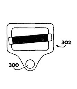
[0030] Referring now to FIGS 8a, 8b, and 8c, there are shown
perspective pictorial
views of examples of attachment devices 30. Respectively, a friction buckle
302, a solid
ring 304, and a rope grab 306. Each attachment device 302, 304, 306 is
equipped with a
ring 300 suitable for sliding through proximal opening 16 of body member 12.
However,
attachment devices 302, 304, 306 form no part of snap-hook 10 and are shown
merely to
illustrate the intended use. Further, while a friction buckle 302, a solid
ring 304, and a rope
grab 306 have been shown for purposes of disclosure, those of skill in the art
will
comprehend that numerous other attachment devices may be substituted therefor
to meet a
particular operating circumstance or environment.
8
Date Recue/Date Received 2022-04-01