Note: Descriptions are shown in the official language in which they were submitted.
"Apparatus and Method to Check Extracorporeal Circuit"
DESCRIPTION
BACKGROUND OF THE INVENTION
The invention relates to extracorporeal treatment systems and methods, and
particularly to
verifying the connection of an extracorporeal circuit to an extracorporeal
treatment assembly.
Extracorporeal treatment assemblies typically treat blood withdrawn from a
patient and infuse
the treated blood into the patient. These assemblies generally include an
extracorporeal
treatment apparatus having a pump or pumps, a blood treatment device and a
separable
extracorporeal circuit having blood and other liquid passages. The
extracorporeal treatment
apparatus may be a monitor for hemodialysis and hemo(dia)filtration and the
treatment device
may be a blood filter. The separable extracorporeal circuit may be a blood
tubing set which
attaches to the monitor.
Prior to a blood treatment session, an extracorporeal circuit is selected,
mounted to the
extracorporeal treatment apparatus and primed with a liquid. Priming generally
involves flushing
the passages in the extracorporeal circuit with priming liquid to purge gases
from the passages.
The blood treatment session commences after the circuit has been filled with
the priming liquid
and the gases flushed from the passages in the circuit. During the blood
treatment session, the
.. blood passages in the circuit may receive blood withdrawn from a patient,
move the blood
through a blood treatment device and infuse the treated blood into the
patient. After the blood
treatment session, the circuit may be removed from the apparatus and disposed
of such as by
being treated as medical waste.
An extracorporeal treatment apparatus may operate with various types of
extracorporeal
.. circuits. For example, an extracorporeal treatment apparatus may be
configured to receive an
extracorporeal circuit for normal sized adult patients, an extracorporeal
circuit for pediatric
patients, and a Low Weight Low Volume (LWLV) blood circuit for smaller adults.
To start a blood
treatment session, a human operator selects the type of extracorporeal circuit
corresponding to
the patient. The operator mounts the selected circuit to the apparatus. The
operator may also
enter operational settings for a desired treatment mode and information
regarding the patient,
e.g., normal sized adult, child or small adult, into the controller for the
treatment apparatus.
The different types of extracorporeal circuits may differ in the sizes of
their liquid flow passages
circuit. The blood passages for the LWLV and pediatric circuits may have
smaller diameters
than the blood passages in a circuit for the normal sized adult. The
difference in sizes of the
.. passages affects the amount of liquid moved through the passage during each
pump rotation.
1
CA 3060041 2019-10-23
The operational settings of the treatment apparatus cause the pump to rotate
at rates intended
to cause a certain rate of liquid to flow through the passages in the circuit.
The operational
settings for the extracorporeal treatment system may differ for each of the
different types of
circuits. For example, the pump speed may be faster for a normal sized circuit
than for the
LWLV circuit or the pediatric circuit.
If the wrong circuit is connected to the treatment apparatus, the operational
settings may cause
the pumps to withdraw or infuse blood and other liquids at rates different
than the prescribed
rates for the treatment. In particular, the rate of blood withdrawal or
infusion may differ from the
desired rates if the wrong type of blood circuit is connected to the treatment
apparatus.
In view of the potential for the withdrawal or infusion of liquids at non-
prescribed rates, there is a
long felt need for an automatic process to detect whether the extracorporeal
circuit connected to
an extracorporeal treatment apparatus is the type of circuit that corresponds
to the operational
settings of the apparatus. Further, there is a long felt need for an automatic
process to confirm
or determine that an appropriate extracorporeal circuit is connected to an
extracorporeal
.. treatment apparatus.
BRIEF DESCRIPTION OF THE INVENTION
An extracorporeal apparatus and method has been conceived and is disclosed
here to
automatically: (i) identify the extracorporeal circuit mounted to the
extracorporeal treatment
apparatus and match the identified circuit to the operational settings for the
apparatus, and (ii)
determine whether a passage or passages is leaking in the circuit. During a
startup procedure,
such as a priming procedure, a controller for the extracorporeal treatment
apparatus performs a
pressure check on an extracorporeal circuit mounted to the apparatus. The
pressure check is
used to determine if the proper circuit is connected to the apparatus and if
there is a leak in the
circuit.
.. An extracorporeal treatment apparatus has been conceived and invented which
is configured to
receive an removable extracorporeal circuit, the treatment apparatus includes:
a pump
configured to pump a liquid through a passage in the extracorporeal circuit; a
flow coupling
connectable to an outlet end of the passage, wherein the impedance to liquid
flow through the
passage at the flow coupling is a constant or known value; a controller
including a processor
and an electronic memory storing instructions, data regarding operational
settings of the
treatment apparatus and data correlating different types of the extracorporeal
circuits to specific
operational settings, the instructions when executed by the processor cause
the controller to: (i)
actuate the pump to move the liquid through the passage while the outlet of
the passage is
connected to the flow coupling; (ii) receive data indicative of a pressure of
the liquid flowing
through the passage from a pressure sensor monitoring the pressure of the
liquid; (iii) identify if
a pressure range in the stored data corresponds to the received data
indicative of the pressure
2
CA 3060041 2019-10-23
in the passage; (iv) correlate the identified pressure range to a particular
type of extracorporeal
circuit, and (v) determine if the identified circuit type corresponds to the
operational settings of
the treatment apparatus or identify the operational settings for the treatment
apparatus that
conform to the identified circuit type.
The received pressure data may be data output by a pressure sensor monitoring
the pressure of
a priming liquid flowing through the passage. The instructions may be executed
by the
controller during a priming operation of the apparatus. The data indicative of
the pressure may
be received during a portion of the priming process occurring after the
priming fluid has filled the
passages in the circuit.
The instructions, when executed by the processor, may also cause the
controller to
automatically confirm that the outlet to the passage is connected to flow
coupling prior to the
actuation of the pump. This confirmation may include a determination that a
door covering a
connection to the drainage container is open to indicate that the outlet of
the liquid passage is
connected to the drainage container.
The flow coupling may be a coupling to the drainage container included in the
treatment
apparatus. The flow impedance at the flow coupling may be due to a flow
restriction having a
smaller cross-sectional flow area than does any other portion of the liquid
passage extending
from the pump to the outlet. The flow restriction may be a connector included
in an inlet portion
of the drainage container, such as a Luer connector.
A method has been conceived and invented to monitor a liquid flow through a
passage in an
extracorporeal circuit connected to an extracorporeal treatment apparatus
having a pump, the
method comprising: connecting the passage to the pump; connecting the outlet
of the passage
to a container having a known or constant flow impedance; pumping liquid
through the passage
and into the container; sensing a value of a condition of the pump while
pumping the liquid or of
the liquid flowing through the passage between the pump and the container; and
determining
whether the sensed value differs from an expected value for the condition.
An extracorporeal treatment assembly has been conceived and invented
comprising: an
extracorporeal treatment apparatus including a pump configured to move a
liquid through a
liquid passage mountable to the pump and a controller that governs the pump;
an
extracorporeal circuit connectable to the treatment apparatus, wherein the
circuit includes the
liquid passage mountable to the pump; a drainage container connectable to the
liquid passage,
wherein the drainage connector includes a connector configured to connect to
the liquid
passage, wherein the connector has a known impedance to the flow of liquid
from the liquid
passage into the drainage container; a pressure sensor configured to sense a
liquid pressure in
the passage; a memory storing a correlation between an expected pressure value
for at least
one type of a plurality of types of the extracorporeal circuit, and the
controller which: (i) governs
3
CA 3060041 2019-10-23
the pump to move liquid drawn into the extracorporeal circuit from the source
of the liquid and
pump the liquid through the liquid passage and into the drainage container;
(ii) monitors
pressure data from the pressure sensor while the liquid flows through the
liquid passage, (iii)
generates an alarm if the pressure data indicates the pressure of the liquid
in the liquid passage
does not conform to the expected pressure value.
The extracorporeal treatment assembly may include a blood treatment device
having a blood
chamber and a liquid chamber separated by porous membrane from the blood
chamber, and
the inlet to the extracorporeal circuit and the liquid passage are in fluid
communication with the
blood chamber. The liquid may be a primping liquid and the source is a source
of the priming
liquid.
In accordance with a first main independent aspect an extracorporeal treatment
apparatus
configured to receive an extracorporeal circuit has been provided, the
treatment apparatus
comprising a pump configured to pump a liquid through a passage in the
extracorporeal circuit
while the circuit is mounted to the treatment apparatus; a flow coupling
connectable to an outlet
of the passage, the flow impedance at the flow coupling is a constant or known
value, wherein
the flow coupling includes an inlet coupling to a drainage container; and a
controller which is
configured to: control the pump to move liquid through the passage, and the
flow coupling;
collect data indicative of a pressure condition of the liquid flowing through
the passage and flow
coupling; identify a parameter value which correlates to the indicated
pressure condition,
wherein the identified parameter value is one a plurality of known parameter
values or ranges,
wherein each value or range of values uniquely corresponds to a circuit type
of a plurality
extracorporeal circuit types that may be mounted to the treatment apparatus,
and determine an
operational setting for the treatment apparatus or determine whether a current
operational
setting is proper based on the type of extracorporeal circuit corresponding to
the identified
parameter value, wherein the flow impedance at the flow coupling is due to a
flow restriction, the
flow restriction being in a connector included in the inlet portion of the
drainage container.
In accordance with a second main independent aspect, there is provided a
method to monitor a
continuous liquid flow through a liquid passage in an extracorporeal circuit
connected to an
extracorporeal treatment apparatus having a pump, the method comprising:
connecting the liquid passage to the pump;
connecting an outlet of the liquid passage to a drainage container having a
known or
constant flow impedance;
pumping liquid through the liquid passage and into or through the drainage
container;
sensing a value of a condition of the pump while pumping the liquid or of the
liquid
flowing through the passage between the pump and the drainage container, and
4
Date Recue/Date Received 2020-12-11
issuing a notice or ceasing pumping if the sensed value differs from an
expected value
for the condition,
characterized in that the sensing of the liquid pressure occurs while the
liquid flows
through a flow restriction, and in that said flow restriction is in a
connector included in an inlet
portion of the drainage container.
In accordance with a first auxiliary independent aspect an extracorporeal
treatment apparatus
configured to receive an extracorporeal circuit has been provided, the
treatment apparatus
comprising a pump configured to pump a liquid through a passage in the
extracorporeal circuit
while the circuit is mounted to the treatment apparatus; a flow coupling
connectable to an outlet
.. of the passage, the flow impedance at the flow coupling is a constant or
known value; and a
controller which is configured to: store a flow resistance value at the flow
coupling, said flow
resistance value being either a value set by the operator before starting
apparatus or a pre-
stored constant value known by the controller before starting the apparatus;
control the pump at
a speed corresponding to a set fluid flow value to move liquid through the
passage, and the flow
coupling; collect actual data indicative of a pressure condition of the liquid
flowing through the
passage and flow coupling during control of the pump at said speed; store a
data uniquely
4a
Date Recue/Date Received 2020-12-11
corresponding to an expected circuit type mounted to the treatment apparatus
out of a plurality
extracorporeal circuit types that may be mounted to the treatment apparatus,
optionally said
data being acquired by the apparatus or set by the operator before starting
the operation of the
apparatus; retrieving a sectional dimension of the mounted circuit type based
on said data
uniquely corresponding to the mounted circuit type; determine the expected
data indicative of an
expected pressure value of the liquid flowing through the passage and flow
coupling as a
function of the set fluid flow value or pump speed and of the sectional
dimension of the mounted
circuit type and as a function of said flow resistance value; comparing the
expected data with
the actual data; determining as a function of the comparing step whether the
expected circuit
type corresponds to the circuit type actually mounted on the apparatus.
In accordance with a second aspect depending on any of the 1st aspects the
received data is
data output by a pressure sensor monitoring the pressure of the liquid flowing
through the
passage.
In accordance with a 3rd aspect depending on the previous aspects the
extracorporeal
treatment apparatus further comprises a pressure sensor monitoring the
pressure of the liquid
flowing through the passage, a signal from the pressure sensor being received
by the controller.
In accordance with a 4th aspect depending on the previous aspects the data
indicative of the
pressure is collected during a priming operation of the apparatus.
In accordance with a 5th aspect depending on the previous aspects the
controller is configured
to perform the steps of controlling, collecting, identifying and determining
during a priming
operation of the apparatus and/or before starting an extracorporeal blood
treatment operation, in
particular at least the steps of controlling and collecting being performed
during a priming
operation of the apparatus and the steps of identifying and/or determining
being performed
either during a priming operation of the apparatus or after the priming
operation and before
starting the extracorporeal blood treatment operation
In accordance with a 6th aspect depending on the previous aspects 4 or 5 the
data indicative of
the pressure is received substantially at the end of the priming.
In accordance with a 7th aspect depending on the previous aspects the flow
coupling includes
an inlet coupling to a liquid drain, such as a liquid container included in
the treatment apparatus.
In accordance with a 8th aspect depending on the previous aspects the flow
impedance at the
flow coupling is due to a flow restriction having a smaller cross-sectional
flow area for the liquid
than does any portion of the liquid passage extending from the pump to the
flow coupling.
In accordance with a 9th aspect depending on the previous aspects the flow
coupling includes a
protruding portion configured to connect to outlet of the passage by direct
insertion into outlet of
5
CA 3060041 2019-10-23
the passage, the protruding portion defining internally a flow conduit
receiving the fluid and
directing the fluid towards a liquid drain.
In accordance with a 10th aspect depending on the previous aspect the
protruding portion is in
the form of a substantially circular tube, said tube having in particular a
smooth outer lateral
surface without means for attaching to the passage.
In accordance with a 11th aspect depending on the previous aspects 9 or 10 the
flow coupling
includes an external crown at least partially embracing the protruding
portion, the external crown
including a structure for attaching to the passage.
In accordance with a 12th aspect depending on the previous aspects the flow
coupling
comprises a male Luer connector for coupling to a corresponding female Luer
connector of the
passage.
In accordance with a 13th aspect depending on the previous aspects the
controller is configured
to further automatically check that the passage is connected to the flow
coupling prior to the
actuation of the pump.
In accordance with a 14th aspect depending on the previous aspects the
apparatus comprises a
sensor configured to sense a specific condition of the flow coupling, said
specific condition
being either a non coupled condition of the flow coupling to the passage or a
condition in which
coupling between the flow coupling and the passage is possible.
In accordance with a 15th aspect depending on the previous aspect the specific
condition
sensed by the sensor is a condition of open door allowing coupling of the flow
coupling to the
passage or of closed door indicating a non coupled condition of the flow
coupling to the
passage.
In accordance with a 16th aspect depending on the previous aspects the
confirmation that the
liquid passage is connected to the drainage container includes determining if
a door covering a
liquid connection is open.
In accordance with a 17th aspect depending on the previous aspects the flow
coupling includes
a connector included in an inlet portion of a drainage container.
In accordance with a 18th aspect depending on the previous aspects the flow
coupling includes
a Luer connector.
In accordance with a 19th aspect depending on the previous aspects the
controller is configured
to sense the liquid pressure for a certain period of pumping, and the sensed
pressure
determined based on several pressure sensing events during the certain period.
In accordance with a 20th aspect depending on the previous aspect the sensed
pressure is an
average of the pressures measured during the pressure sensing events.
6
CA 3060041 2019-10-23
In accordance with a 21st aspect depending on the previous aspects the
extracorporeal circuit
may be one of a plurality of selectable types of circuits and the liquid
passage in at least one of
the circuit types has a different size than the liquid passage in another one
of the circuit types.
In accordance with a 22nd aspect depending on the previous aspects the pump is
an occlusive
pump, particularly a peristaltic pump, and the passage is a deformable tube,
wherein the
pumping includes the pump pinching the tube to move the priming liquid through
the passage.
In accordance with a 23rd aspect depending on the previous aspects the flow
impedance at the
flow coupling is the flow resistance at the flow coupling.
In accordance with a 24th aspect depending on the previous aspects the
controller has a
memory storing a flow resistance value at the flow coupling, said flow
resistance value being
either a value set by the operator before starting apparatus or a pre-stored
constant value
known by the controller before starting the apparatus.
In accordance with a 25th aspect depending on the previous aspects the
controller is not
configured to calculate a flow resistance of the flow coupling.
In accordance with a 26th aspect depending on the previous aspects the flow
coupling
determines a local loss of head in the extracorporeal circuit.
In accordance with a 27th aspect depending on the previous aspects the
controller is configured
to: control the pump at a speed corresponding to a set fluid flow value to
move liquid through
the passage, and the flow coupling; collect actual data indicative of a
pressure condition of the
liquid flowing through the passage and flow coupling during control of the
pump at said speed;
store a data uniquely corresponding to an expected circuit type mounted to the
treatment
apparatus out of a plurality extracorporeal circuit types that may be mounted
to the treatment
apparatus, optionally said data being acquired by the apparatus or set by the
operator before
starting the operation of the apparatus; retrieving a sectional dimension of
the mounted circuit
type based on said data uniquely corresponding to the mounted circuit type;
determine an
expected data indicative of an expected pressure value of the liquid flowing
through the
passage and flow coupling as a function of the set fluid flow value or pump
speed and of the
sectional dimension of the mounted circuit type; comparing the expected data
with the actual
data; determining as a function of the comparing step whether the expected
circuit type
.. corresponds to the circuit type actually mounted on the apparatus.
In accordance with a 28th aspect depending on the previous aspect the
controller is further
configured to store a flow resistance value at the flow coupling, said flow
resistance value being
either a value set by the operator before starting apparatus or a pre-stored
constant value
known by the controller before starting the apparatus; determine the expected
data indicative of
an expected pressure value of the liquid flowing through the passage and flow
coupling as a
7
CA 3060041 2019-10-23
function of the set fluid flow value or pump speed and of the sectional
dimension of the mounted
circuit type and as a function of said flow resistance value.
In accordance with a 29th aspect depending on the previous aspects the
controller is further
configured to determine an operational setting for the treatment apparatus or
determine whether
a current operational setting is proper based on the type of extracorporeal
circuit corresponding
to the identified parameter value.
In accordance to a 30th independent aspect an extracorporeal treatment system
is provided
comprising an extracorporeal treatment apparatus in accordance with anyone of
the previous
aspects and an extracorporeal circuit, the extracorporeal circuit including at
least a passage
having an outlet connectable to the flow coupling.
In accordance with a 31st aspect depending on the previous aspect the flow
coupling has a flow
restriction with a cross-sectional flow area smaller than a cross-sectional
flow area of the
passage.
In accordance with a 32nd aspect depending on the previous aspects 30 or 31
the flow coupling
has a flow restriction with a cross-sectional flow area smaller than a cross-
sectional flow area of
any portion of the passage extending from the pump to the flow coupling.
In accordance with a 33rd aspect depending on the previous aspects 30 to 32
the
extracorporeal circuit is mounted on the apparatus with the pump configured to
act on the
passage and the outlet of the passage connected to the flow coupling.
In accordance with a 34th aspect depending on the previous aspects 30 to 33
the outlet of the
passage has a cross-sectional flow area configured to receive a protruding
portion of the flow
coupling to connect by insertion into outlet of the passage, the protruding
portion defining
internally a flow conduit receiving the fluid and directing the fluid towards
a liquid drain.
In accordance with a 35th aspect depending on the previous aspects 30 to 34
the flow coupling
protruding portion coupled to the passage determines a local loss of head in
the extracorporeal
circuit.
In accordance with a 36th aspect depending on the previous aspects 30 to 35
the
extracorporeal circuit comprises at least a treatment unit having at least a
first chamber and at
least a second chamber separated from one another by a semipermeable membrane;
at least a
blood removal line connected to an inlet port of the first chamber and
configured to remove
blood from a patient, at least a blood return line connected with an outlet
port of the first
chamber and configured to return treated blood to the patient, the blood
removal line, said
passage being defined by a portion of the blood removal line or by a portion
of the blood return
line.
8
CA 3060041 2019-10-23
=
In a further independent 37th aspect a method to monitor a continuous liquid
flow through a
liquid passage in an extracorporeal circuit connected to an extracorporeal
treatment apparatus
having a pump is provided, the method comprising connecting the liquid passage
to the pump;
connecting the outlet of the liquid passage to a device having a known or
constant flow
impedance; pumping liquid through the liquid passage and into or through the
device; sensing a
value of a condition of the pump while pumping the liquid or of the liquid
flowing through the
passage between the pump and the device, and issuing a notice or ceasing
pumping if the
sensed value differs from an expected value for the condition.
In accordance with a 38th aspect depending on the previous aspect the sensed
value and the
condition is a pressure of the liquid flowing through the passage.
In accordance with a 39th aspect depending on the previous aspects 37 or 38
the sensed value
is electrical current amperes and the condition is electrical current driving
the pump.
In accordance with a 40th aspect depending on the previous aspects 37 to 39
the liquid is a
priming liquid and the pumping occurs while priming the circuit.
In accordance with a 41st aspect depending on the previous aspect the sensing
of the liquid
pressure occurs during an end portion of the priming.
In accordance with a 42nd aspect depending on the previous aspects 37 to 41
the sensing of
the liquid pressure occurs while the liquid flows through the flow
restriction.
In accordance with a 43rd aspect depending on the previous aspect the flow
restriction has a
smaller cross-sectional flow area for the liquid than does any portion of the
liquid passage
extending from the pump to the outlet.
In accordance with a 44th aspect depending on the previous aspects 37 to 43,
the method
further comprises automatically confirming that an outlet to the liquid
passage is connected to
the drainage container prior to the pumping step.
In accordance with a 45th aspect depending on the previous aspect the
confirmation that an
outlet of the liquid passage is connected to the drainage container includes
determining if a door
covering a liquid connection to the drainage device is open which indicates
that the outlet of the
liquid passage is connected to the drainage container.
In accordance with a 46th aspect depending on the previous aspects 37 to 45
the flow
restriction is in a connector included in an inlet portion of the drainage
container.
In accordance with a 47th aspect depending on the previous aspects 37 to 46
the flow
restriction is in a Luer connector included as part of the drainage container.
In accordance with a 48th aspect depending on the previous aspects 37 to 47
the liquid
pressure is sensed for a certain period of pumping, and the sensed pressure
determined based
on several pressure sensing events during the certain period.
9
CA 3060041 2019-10-23
In accordance with a 49th aspect depending on the previous aspect the sensed
pressure is an
average of the pressures measured during the pressure sensing events.
In accordance with a 50th aspect depending on the previous aspects 37 to 49
the
extracorporeal circuit may be one of a plurality of selectable types of
circuits and the liquid
passage in at least one of the circuit types has a different size than the
liquid passage in
another one of the circuit types, wherein the sensed liquid pressure will
depend on the circuit
type connected to the extracorporeal apparatus.
In accordance with a 51st aspect depending on the previous aspects 37 to 50
the method
further comprises the following steps: control the pump at a speed
corresponding to a set fluid
flow value to move liquid through the passage, and the flow coupling; collect
actual data
indicative of a pressure condition of the liquid flowing through the passage
and flow coupling
during control of the pump at said speed; store a data uniquely corresponding
to an expected
circuit type mounted to the treatment apparatus out of a plurality
extracorporeal circuit types that
may be mounted to the treatment apparatus, optionally said data being acquired
by the
apparatus or set by the operator before starting the operation of the
apparatus; retrieving a
sectional dimension of the mounted circuit type based on said data uniquely
corresponding to
the mounted circuit type; determine an expected data indicative of an expected
pressure value
of the liquid flowing through the passage and flow coupling as a function of
the set fluid flow
value or pump speed and of the sectional dimension of the mounted circuit
type; comparing the
expected data with the actual data; determining as a function of the comparing
step whether the
expected circuit type corresponds to the circuit type actually mounted on the
apparatus.
In accordance with a 52nd aspect depending on the previous aspect the method
further
comprises the following step: determine an operational setting for the
treatment apparatus or
determine whether a current operational setting is proper based on the type of
extracorporeal
circuit corresponding to the identified parameter value.
In accordance with a 53rd aspect depending on the previous aspect the method
further
comprises the following steps: store a flow resistance value at the flow
coupling, said flow
resistance value being either a value set by the operator before starting
apparatus or a pre-
stored constant value known by the controller before starting the apparatus;
determine the
expected data indicative of an expected pressure value of the liquid flowing
through the
passage and flow coupling as a function of the set fluid flow value or pump
speed and of the
sectional dimension of the mounted circuit type and as a function of said flow
resistance value.
In accordance with a 54th aspect depending on the previous aspects 37 to 53
the method
further comprises the step of recalling from a memory a flow resistance of the
flow coupling
without previously calculating it.
CA 3060041 2019-10-23
In accordance with a 55th aspect depending on the previous aspects 37 to 54
the method
further comprises the step of: storing a flow resistance value at the flow
coupling, said flow
resistance value being either a value set by the operator before starting
apparatus or a pre-
stored constant value known by the controller before starting the apparatus.
In accordance with a 56th aspect depending on the previous aspects 37 to 55
the flow
impedance at the flow coupling is the flow resistance at the flow coupling.
It is also known from document W02008/125894 an apparatus for extracorporeal
blood
treatment having an extracorporeal circuit connected to a blood chamber of a
membrane
device. A pump displaces a priming fluid from a source of a priming fluid to a
drainage for
discharging the priming fluid. A control unit is provided with a processor
which controls the
pump at a preset first flow rate value, and receives from a pressure sensor a
first pressure
value, compares the first pressure value with a reference pressure value and,
on the basis of
this comparison, determines whether or not the extracorporeal circuit is of a
pediatric type or of
an adult type.
BRIEF DESCRIPTION OF THE DRAWINGS
FIGURE 1 is a perspective view of an extracorporeal treatment apparatus in
which portions of
the housing have been cut away to show an internal liquid container and a
drainage container.
FIGURE 2 is a front view of the extracorporeal circuit mounted to the
extracorporeal treatment
apparatus.
FIGURE 3 is a schematic diagram of an extracorporeal blood treatment assembly
with
separable extracorporeal circuit.
FIGURE 4 is a flow diagram illustrating the flow impedance at an outlet of the
extracorporeal
circuit. =
FIGURES 5 and 6 are perspective views of an exemplary priming liquid discharge
container,
wherein Figure 5 shows the cover doors opened and Figure 6 shows the doors
closed.
FIGURE 7 shows a flow chart of an exemplary process for determining whether
the proper
extracorporeal circuit is connected to an extracorporeal treatment apparatus.
DETAILED DESCRIPTION OF THE INVENTION
FIGURE 1 is a schematic diagram of an extracorporeal treatment assembly 10
which is adapted
to receive a separable blood circuit. The treatment assembly may be a monitor
for
hemodialysis, hemo(dia)filtration, ultrafiltration, treatment and infusion of
blood or other
extracorporeal treatment of a mammalian patient, such as a human. The
treatment assembly
includes a mount 12 to receive an extracorporeal circuit, and a mount 14 to
receive a blood
treatment device, such as a blood filter.
11
CA 3060041 2019-10-23
The treatment assembly 10 houses one or more pumps 16, e.g., peristaltic pump
or other
positive displacement pump that moves blood and other liquids through tubular
passages in the
extracorporeal circuit. The pumps 16 are graphically represented by a recessed
U-shaped track
for rotating pump rollers. The tubular passages are placed in the track and
pinched by the
rollers of the pump. As the rollers turn, they force liquids through the
passages at a rate
corresponding to the rotational speed of the pump.
The pumps, e.g., the motors turning the rollers, may be controlled by a
controller, e.g., controller
18, housed within the assembly 10. The controller may include a computer
processor(s) and
electronic storage for data and program instructions. The stored data may
include operational
settings for various treatments to be performed with the extracorporeal
treatment apparatus,
sensor measurements including measurements of liquids flowing in the tubes,
and inputs
manually made by an operator of the apparatus. The stored operational settings
may be pump
speeds, treatment duration and ranges of expected pressures of liquids in the
passages during
the various treatments that can be performed by the apparatus. Associated with
each of the
treatments may be a type of extracorporeal circuit, wherein the operational
settings for a
treatment are based on the prescribed type of extracorporeal circuit being
mounted to the
apparatus 10.
The controller 18 may control a graphical user input and display system 20
which may be a
touch screen display. The controller may generate for the input and display
system 20 text,
data or other graphical representations of the operational settings of the
assembly and
information regarding current operational conditions, such as pressures in the
passages of the
circuit. The input and display system 20 may include input devices, such as
keys, knobs and
graphical icons, to be used by a human operator to input settings to the
apparatus. For
example, the operator may input settings specifying a selected treatment and
type of patient to
receive the treatment. The controller receives the input data and uses the
data to select a
corresponding control setting stored in the memory of the controller.
The controller may include an electronic memory storing data correlating the
expected pressure
in the liquid passage during the pressure check for treatment mode of the
extracorporeal
treatment apparatus. The controller compares the pressure data obtained during
the pressure
check to the expected pressure range corresponding to the type of
extracorporeal circuit that
should be connected to the treatment apparatus. If the sensed pressure level
is outside the
expected range, the controller issues an alarm to alert the user that an
improper extracorporeal
circuit has been mounted to the apparatus. The controller may not allow blood
treatment to start
if the sensed pressure level is outside of the expected range in addition to
or as an alternative to
issuing an alarm.
12
CA 3060041 2019-10-23
In addition to governing the pumps 16 connected to the circuit, the controller
18 may also
control other pumps, valves, heating devices and other systems housed in the
apparatus to
generate priming liquids and treatment solutions to be used with the
extracorporeal circuit and
treatment session. The apparatus may store liquids 22 for priming and
generation of treatment
solutions.
In addition, the apparatus may have a drainage for example a drainage
container 24 for
receiving used priming liquid, filtrate liquids and used treatment solutions.
The drainage, for
example the drainage container, may have an inlet coupling 26 attached to the
housing for the
apparatus. The inlet coupling may be, for example, part of a Luer connector,
which is adapted to
couple to a matching Luer connector on the end of a liquid passage of the
extracorporeal circuit.
FIGURE 2 is a front view of a portion of the extracorporeal treatment
apparatus 10 on which is
mounted an extracorporeal circuit 28. The circuit 28 may comprise flexible
hollow plastic tubular
passages (or tubes) 30 and a rigid plastic frame (or cassette) 32 that
supports the passages.
The frame 32 attaches to the mount 14 on the apparatus 10. The back of the
frame 32 may
include a fastener which connects to a matching fastener of the mount 14.
Mounting the frame 32 to the treatment apparatus aligns the tubes 30 with the
pumps 16,
sensors (indicated by sensor cover 34) and other components of the treatment
apparatus. The
sensors may include one or more pressure sensors which measures the pressure
in the tubes.
The ends of the tubes may include a connector 36, such as a Luer connector
which may be a
slip or locking connector.
In general the extracorporeal circuit 28 may include an arterial line
including a main tract having
one end configured to be connected to a patient for withdrawing blood and the
other end
connected to a first (or arterial) chamber of the rigid frame 32. A second
tract of the arterial line
receives blood from the arterial chamber and allows directing it towards the
treatment unit (e.g.
dialyzer).
A venous line receives the treated blood form the treatment unit and a main
tract of the venous
line brings the blood to a second (venous chamber) of the rigid frame 32. A
second tract of the
venous line has one end connected to the venous chamber and the other end
connectable to a
patient to return the treated blood.
Either one or both the arterial and venous chambers includes a pressure sensor
to detect the
respective blood pressure. In particular the pressure sensor/s is/are placed
on an upper portion
of the camber destined to be occupied by air during treatment/priming
procedures.
The extracorporeal apparatus 10 may receive different types of extracorporeal
circuits. The
types of extracorporeal circuits may include a circuit for normal sized adult
patients, a circuit for
pediatric patients which has relatively small diameter tubes, and a Low Weight
Low Volume
(LWLV) circuit for smaller adults which may also having small diameter tubes.
The appropriate
13
CA 3060041 2019-10-23
circuit to be mounted to the apparatus depends on the treatment setting. The
treatment setting
may be inputted to the controller by an input device, such as a virtual button
icon 38 on the
touch sensitive display 20.
In other terms the various types of extracorporeal circuits differ mainly in
the respective tube
diameters and/or venous and arterial chamber volume or shape.
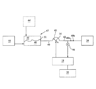
FIGURE 3 is a schematic diagram of an extracorporeal treatment assembly
including the
extracorporeal treatment apparatus 10 and extracorporeal circuit which is
represented by tubing
passages 40 and 42. The configuration of the treatment assembly and circuit
shown in Figure 3
is for priming the circuit with a priming liquid provided from a source of
priming liquid 44 or 44'.
The priming liquid may be a saline solution or other liquid, such as supplied
by a liquid storage
container 22 (Fig. 2) the priming liquid may alternatively be on-line prepared
by the machine
receiving water from a continuous water source. The priming liquid is pumped
into the passages
40, 42 of the circuit during a pre-treatment operation performed by the
treatment assembly. The
priming liquid may purge the passages 40, 42 of air and other gases to insure
that air or gases
are not infused into the vascular system of a patient during the initiation of
blood treatment.
The priming liquid may be pumped from a liquid source 44, 44' connected to a
blood treatment
device, such as a blood filter 47. The priming liquid source 44 may be
connected to a blood
chamber 48 of the filter 47 or the source 44' may be connected to a filtrate
chamber 50 of the
filter. A permeable membrane 51 separates the filtrate chamber from the blood
chamber, and
allows priming liquid to move between the blood and filtrate chambers. A pump
16 (Fig. 2) may
receive a portion of the passage 42 such as a loop 45 of tube passage which
may be mounted
in the track of a peristaltic pump. The pump may move liquid through the
passages 40, 42 by
rollers which move against the loop of the tube passage and positively
displace the liquid
through the passage.
The pressure sensor 46 may be positioned to sense pressure in a portion of the
passage 42
extending between the pump 16 and an outlet connector 49a, e.g., a female Luer
connector.
Luer connector assemblies, including a male and female connectors, are used to
connect
extracorporeal tube passages to other components such as catheters, containers
which
dispense or receive liquids, and implanted blood ports.
The pressure sensor 46 may also be mounted on the rigid frame 32, for example
being active
on one of the arterial and venous chamber to detect the fluid pressure in the
chamber.
During the priming operation, the Luer connector 49a of the passage 42 may
connect to a
matching male Luer connector 49b at the inlet of the drainage container 24.
The Luer
connectors 49a, 49b when coupled tougher form a non-leaking and air tight
connection between
the passage 42 and the drainage container 24. The priming liquid draw from the
source 44, 44',
flows through the blood treatment device 47, the tubes 40, 42 and into the
drainage container
14
CA 3060041 2019-10-23
24. The motive force for the priming liquid flow is the pump 16 acting on the
tubes 40, 42. The
priming operation is continued to ensure that the tubes 40, 42 are filled with
liquid and purged of
gases.
FIGURE 4 illustrates the flow through the passage 42 and the impedance to the
flow due to the
male Luer connector 49b at the inlet of the drainage connector. The Luer
connector 49b and
inlet to the drainage container 24 have an impedance 52 to the flow of liquid.
The impedance
52 may be a constant or a known flow resistance to the priming liquid being
pumped into the
drainage container. As shown in Figure 4, the impedance 52 at the inlet to the
male Luer
connector 49b may be due to a narrow throat 53 of that connector. The
impedance 52 at the
Luer connector 49b may be substantial, such as representing at least fifty
percent (50%) of the
impendence to the flow of liquid through the passage 42 between the pump 16
and the drainage
container 24.
The impedance 52, e.g. the flow resistance, at the inlet to the male Luer
connector 49b remains
uniform or constant regardless of the type of extracorporeal circuit connected
to the treatment
apparatus. The flow impedance 52 affects the upstream pressure in the passage
42 as the
impedance applies a backpressure to the liquid flow through the passage. The
pressure sensor
46 monitors the pressure in the passage 42. The pressure in the passage 42 as
sensed by the
pressure sensor 46 is, in part, a function of the impedance 52 at the inlet to
the Luer connector
49b in the passage 42.
FIGURES 5 and 6 are perspective views of an exemplary housing 54 for the
drainage inlet 26
for the liquid discharge container 24 (see Fig. 1). The housing may mount to
the side of the
extracorporeal treatment apparatus, as is shown in Figure 1. The housing
includes a cover door
56a, 56b. Figure 5 shows the cover door 56a, 56b closed and Figure 6 shows the
door open.
The inside surface of the door may include plugs 58 that fit into, when the
door is closed, input
ports 60a, 60b on the front face 62 of the housing. The input ports 60a, 60b
may comprise male
Luer connectors 49b which receives the female Luer connectors 49a of the
passage 42 of the
blood circuit. The doors 56a, 56b may a single door or a pair of doors such
that one door may
be opened to expose one of the ports 60a, 60b while the other door is closed
to seal the other
port 60a, 60b.
FIGURE 7 is a process chart illustrating an example of a method for setting
operational mode
(conditions) of an extracorporeal treatment apparatus, and checking the type
of extracorporeal
circuit mounted to the apparatus. The process flow may involve a pressure
check of the blood
circuit conducted while a passage of the circuit is connected to a port
connected to or otherwise
associated with the treatment apparatus.
In one embodiment, the pressure check may be performed during a liquid priming
process that
occurs before the extracorporeal treatment procedure. The pressure check may
be performed
CA 3060041 2019-10-23
by the extracorporeal treatment apparatus to confirm or determine that the
extracorporeal circuit
connected to the apparatus is a type of circuit that corresponds to the
operational settings of the
apparatus. The pressure check is performed while a liquid passage of the
circuit is connected to
a coupling having a liquid flow impedance/resistance of a known or constant
value. The
pressure check involves monitoring the liquid pressure in a passage of the
extracorporeal circuit
while priming liquid flows through the passage and to a drainage container in
the apparatus to
collect the priming liquid.
A treatment mode is selected for the treatment apparatus, e.g., the monitor,
in step Si. The
treatment mode may be selected by the human operator interacting with the
touch screen
display to input a selected treatment mode command into the screen. The
command is
processed by the controller of the monitor to select from electronic memory
settings, e.g., pump
speeds, and desired pressure range(s), for the pressures to be sensed by the
pressure sensor
monitoring the passages in the circuit during treatment. The settings are
selected from available
settings for various treatments wherein the selected settings correspond to
the settings
matching the treatment mode inputted by the operator. These settings are
stored in the
memory of the controller. The settings may be specific to one or more of the
possible
extracorporeal circuits that may be connected to the monitor.
The operator selects an extracorporeal circuit in step S2 and mounts the
selected circuit to the
monitor in step S3. The mounting of the circuit to the monitor may include
connecting one or
more loops of the passages in the circuit to the pump, step S4, and connecting
an end of one or
more of the tubular passages in the circuit to the source of priming liquid,
step S5.
The selected extracorporeal circuit should be the type of circuit appropriate
for the operational
settings that have been selected by the user for the desired treatment mode.
There is a remote
possibility that the operator inadvertently selects the wrong type of circuit
and mounts the wrong
circuit to the monitor. The pressure check provides an automatic technique to
detect if the
wrong type of extracorporeal circuit is connected to the monitor.
In step S6, the operator connects an outlet of a tubular passage, e.g., blood
tube 42 (Fig. 3) to a
liquid drainage container, such as container 24 shown in Figures 1 and 3. The
outlet of the
passage 42 may have a Luer connector 49a that fits in a matching Luer
connector 49b in one of
the inlet ports 60a, 60b of the inlet housing 26 for the drainage container
24. The monitor may
check whether the doors 56a, 56b on the housing 54 is open before pumping
priming liquid
through the blood circuit in step S7. The door open check is a safeguard to
avoid pumping
priming liquid when the outlet end of the passage(s) in the circuit are not
connected to a
container to receive the priming liquid after flowing through the circuit. The
monitor may not start
pumping if one or more of the doors are closed, which the monitor believes
should be opened.
16
CA 3060041 2019-10-23
The priming liquid is pumped through the circuit in step S8 by the monitor
actuating the pump(s)
to cause the priming liquid to flow from the source 44, 44' of priming liquid
and through the
passages of the circuit. The liquid may cause the priming liquid to be pumped
through the
passages in the extracorporeal circuit for a certain period in step 9, which
is sufficiently long to
.. ensure that the liquid is flowing through the entire passage(s) of the
blood circuit. Alternatively
or in addition to, the liquid may receive data indicating that the priming
liquid is flowing into the
drainage or drainage container, such as from a weight scale monitoring the
weight of the
drainage container.
As the priming liquid flows through the passage 42 and into the drainage
container, the flow is
resisted by constant or known flow impedance 52 at the connection between the
passage and
the inlet to the drainage container, in step S10. The flow impedance may be
created by a Luer
connector that couples the outlet of the blood passage to the drainage
container.
For example, the male Luer connector 49b has a constant impedance 52, e.g.,
flow resistance,
to liquid flow. The flow impedance of the Luer connector may be on the order
of or greater than
the flow impedance of the blood passage. The flow impedance of the Luer
connector may be a
significant contributor or the primary contributor to the total flow impedance
to liquid flow through
the blood passage from the pump to the drainage connector. The pump speed
determines the
rate at which liquid flows through the passage which influences the liquid
pressure in the
passage. The impedance of the blood passage also influences the pressure of
the liquid flowing
through the passage.
The liquid causes the pump to move the priming liquid through the passage(s)
in the blood
circuit at a flow rate that may be unique to the type of circuit corresponding
to the operating
settings for the treatment apparatus. As the priming liquid is pumped through
the circuit
passage, the pressure in the passage is measured by a pressure sensor 46 (Fig.
3), in step
S11. The pressure may be measured repeatedly over a period, such as ten
seconds, and an
average pressure calculated. The average pressure may be compared to known
pressure
ranges stored in the controller. The pressure check is performed while liquid,
e.g., a priming
liquid, is continuously being pumped and flowing through a liquid passage in
the extracorporeal
blood circuit. The liquid pressure in the passage depends on the flow
impedance, e.g.,
restriction, due to the Luer connector, the pump speed and size of the blood
passage. The flow
impedance due to the male Luer connector 49b, is constant and does not change
with different
types of extracorporeal circuits.
The pump speed depends on the treatment setting of the extracorporeal
treatment apparatus.
The pump speed specified in a particular treatment setting will generally
create a pressure in the
passage in a known pressure range. If the size, e.g., diameter, of the passage
differs from the
passage size of the type of circuit corresponding to the treatment setting,
the pressure in the
17
CA 3060041 2019-10-23
passage will be outside of the expected pressure range for the treatment. The
size of the
passage may differ from the expected size if the wrong circuit is connected to
the apparatus. A
pressure that does not fall within the prescribed pressure range for the
expected extracorporeal
circuit indicates that the wrong circuit is connected to the apparatus.
In step S12, the measured pressure obtained from the pressure sensor is
compared by the
controller to a prescribed range of acceptable pressures for the type of
circuit that corresponds
to the operational settings of the extracorporeal treatment apparatus. If the
sensed pressure is
outside the prescribed range, a determination may be made that the wrong
circuit is connected
to the extracorporeal treatment apparatus, in step S13. An alarm, sound and
visual, may be
issued by the controller if the determination is that the wrong circuit type
is mounted to the
monitor, in step S14.
The pressure check of the extracorporeal blood circuit may also include a
determination of
whether the circuit has a liquid leak in the liquid passage between the pump
connection and the
output of the passage. If the measured pressure in the liquid passage during
pumping of the
priming fluid or other fluid, such as blood during treatment, drops below a
threshold pressure
level, a determination may be made by the controller that the passage is
leaking or that the
coupling at the end of the passage leaks. Based on such a determination an
alarm may be
issued by the controller or the pumps may be stopped to cease liquid flow
through the passages
of the circuit.
In addition or as an alternative to determining whether the measured pressure
in the passage
42 is within a prescribed range, the controller may adjust the pump speed to
achieve a desired
pressure in the flow through the passage in the blood circuit. The controller
monitors the
measured pressure in the passage and adjusts the pump speed to achieve the
desired
pressure. When the desired pressure is achieved, the pump speed is compared to
a known
range of acceptable pump speeds corresponding to the type of extracorporeal
circuit expected
to be connected to the extracorporeal treatment apparatus, given the
operational settings for the
apparatus. If the actual pump speed is outside of the range of acceptable pump
speeds, the
controller may issue an alarm or stop the pumps.
Further, the pressure check is performed to detect the type of extracorporeal
circuit connected
to the extracorporeal treatment apparatus. The controller may perform the
pressure check on
the extracorporeal treatment apparatus in one of the manners described above.
The controller
will interpret the results of the pressure check to determine which type of
extracorporeal circuit
is connected to the extracorporeal apparatus. For example, the controller
compares the
measured pressure of the priming liquid flowing through the passage to each of
the expected
pressure ranges corresponding to each of the extracorporeal circuits.
18
CA 3060041 2019-10-23
The controller may determine the type of the circuit that is connected to the
apparatus based on
which pressure range the measured pressure falls within. Once the
determination is made of the
type of circuit mounted to the apparatus, the controller may select and
display the operational
settings for the apparatus that correspond to the type of circuit determined
to be mounted to the
apparatus. The controller may also display the circuit type which is detected
or present a list of
possible circuits if the sensed flow pressure is within the pressure ranges
for two or more
circuits. The operator may view the display and confirm that the determination
of the treatment
mode, operation settings and type of blood circuit are correct before
initiating blood treatment.
A further embodiment may be for the controller to monitor the power needed to
drive the pump,
e.g., current load, as an alternative or in addition to monitoring the
pressure in the liquid
passage in the extracorporeal circuit. The power needed to drive the pump is
related to the
pressure of the liquid being pumped. The greater the pressure the greater the
power needed to
drive the pump. Accordingly, the power driving the pump may be used as a
substitute for or a
check of the pressure sensor measuring the liquid pressure in the liquid
passage.
While the invention has been described in connection with what is presently
considered to be
the most practical and preferred embodiment, it is to be understood that the
invention is not to
be limited to the disclosed embodiment, but on the contrary, is intended to
cover various
modifications and equivalent arrangements included within the spirit and scope
of the appended
claims.
19
CA 3060041 2019-10-23