Note: Descriptions are shown in the official language in which they were submitted.
TITLE
[0001] Mechanical hammer
FIELD
[0002] There is described a mechanical hammer that was developed to drive
posts and
piles, but which has other uses.
BACKGROUND
[0003] United States patent 7,387,173 (Jinnings et al) titled "pile
driver" is an example of
a mechanical hammer.
SUMMARY
[0004] There is provided a mechanical hammer that includes a support
and an elongated
member. The support defines a linear guide track. A support mounting assembly
is provided
on the support for mounting the support. For example, the support may be
mounted to an
articulating boom that is capable of positioning the mechanical hammer in
preparation for use.
The elongated member is laterally confined by the support while being movable
back and forth
along the linear guide track between an extended position extending from the
support and a
retracted position relatively retracted within the support. A rack and pinion
drive assembly is
provided to selectively drive the elongated member along the linear guide
track. The drive
assembly includes two toothed racks mounted on opposed sides of the elongated
member and
extending lengthwise along the elongated member in parallel spaced relation.
Two pinion gears
are rotatably mounted to the support. Each of the two pinion gears engage one
of the two
toothed racks. Two drive motors selectively impart rotation to the pinion
gears, with the pinion
gears engaging the toothed racks to move the elongated member along the linear
guide track.
[0005] Two embodiments of the mechanical hammer will hereinafter be
illustrated and
described. A first embodiment has the two unidirectional drive motors rotate
the pinion gears
which engage the toothed racks to lift the elongated member to the retracted
position, when the
two unidirectional drive motors are deactivated, the elongated member falls by
force of gravity
to the extended position. A second embodiment has four unidirectional drive
motors. When
when activated a first pair of the four unidirectional drive motors rotate the
pinion gears which
engage the toothed racks to move the elongated member to the retracted
position, while a
second pair of the four unidirectional drive motors are deactivated and rotate
freely. When
CA 3060670 2019-10-29
2
activated the second pair of the four unidirectional drive motors rotate the
pinion gears which
engage the toothed racks to drive the elongated member to the extended
position, while the
first pair of the four unidirectional drive motors are deactivated and rotate
freely.
[0006] It is
advantageous to provide an attachment mounting assembly at the first end of
the elongated member. This enables additional mass attachments to be mounted
to the
attachment mounting assembly for the purpose of increasing the mass of the
elongated
member.
[0007] An advantage of
these embodiments is the low profile of the mechanical hammer
for use where there is relatively little clearance. The second embodiment
provides an
additional advantage as the drive motors increase the impact energy by driving
the elongated
member to the extended position when in a vertical orientation. Further, the
second
embodiment can be used in a horizontal or angular orientation as gravity is
not required for
activation.
BRIEF DESCRIPTION OF THE DRAWINGS
[0008] These
and other features will become more apparent from the following description
in which reference is made to the appended drawings, the drawings are for the
purpose of
illustration only and are not intended to be in any way limiting, wherein:
[0009] FIG. 1 is a side elevation view of a mechanical hammer, in a
retracted position.
[0010] FIG.
2 is a side elevation view of the mechanical hammer of FIG. 1, in an extended
position.
[0011] FIG.
3 is an end elevation view, in section, of a first embodiment which is a
gravity
impact version of the mechanical hammer of FIG. 1.
[0012] FIG.
4 is a perspective view, in section, of a second embodiment which is a motor
driven impact version of the mechanical hammer of FIG. 1.
DETAILED DESCRIPTION
[0013] A mechanical
hammer generally identified by reference numeral 10, will now be
described with reference to FIG. 1 through FIG. 4.
CA 3060670 2019-10-29
3
Structure and Relationship of Parts:
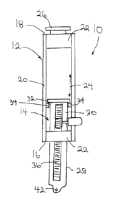
[0014] Referring to FIG. 1 and FIG. 2, mechanical hammer 10 includes a
support, generally
indicated by reference numeral 12 and an elongated member 14. Support 12 has a
first end 16
and a second end 18. When in a vertical orientation first end 16 would be
considered to be a
lower end and second end 18 would be considered to be an upper end. Support 12
is in the
form of a frame having has longitudinal members 20 with box form connective
members 22 at
first end 16 and second end 18 connecting the four longitudinal members 20.
Referring to FIG.
3, there are four longitudinal members 20. Referring to FIG. 1 and FIG. 2,
support 12 defines
a linear guide track, generally indicated by arrow 24. A support mounting
assembly, generally
indicated by reference numeral 26, is provided at second end 18 of support 12.
Support
mounting assembly 26 is used to mount support 12 to an articulating boom (not
shown) that is
capable of positioning mechanical hammer 10 in preparation for use.
[0015] Referring to FIG. 1 and FIG. 2, elongated member 14 has a first end
28 and a second
end 30. When in a vertical orientation, first end 28 would be considered to be
a lower end and
second end 30 would be considered to be an upper end. Elongated member 14 is
laterally
confined by support 12 while being movable back and forth along linear guide
track 24 between
an extended position extending from support 12, as illustrated in FIG. 2 and a
retracted position
relatively retracted within support 12, as illustrated in FIG. 1. Referring to
FIG. 2, a first stop
32 is positioned at second end 30 of elongated member 14 and a second stop 34
is mounted to
support 12. First stop 32 engages second stop 34 to limit movement in the
extended position
of elongated member 14 along linear guide track 24.
[0016] Referring to FIG. 1 and FIG. 2, a rack and pinion drive assembly is
provided to
selectively drive elongated member 14 along linear guide track 24. Referring
to FIG. 3, the
drive assembly includes two toothed racks 36 mounted on opposed sides of
elongated member
14. Referring to FIG. 1 and FIG. 2, toothed racks 36 extend lengthwise along
elongated
member 14. Referring to FIG. 3, toothed racks 36 are in parallel spaced
relation. Two pinion
gears 38 are rotatably mounted to support 12. Each of pinion gears 38 engage
one of two
toothed racks 36. Two drive motors 40 selectively impart rotation to pinion
gears 38, with
CA 3060670 2019-10-29
4
pinion gears 38 engaging toothed racks 36 to move elongated member 14 along
linear guide
track 24 between the retracted position illustrated in FIG. 1 and the extended
position illustrated
in FIG. 2. Referring to FIG. 4, there are a total of four drive motors 40,
with two drive motors
40 positioned on each side of elongated member 14.
Operation:
[0017] Elongated member 14 of mechanical hammer 10 moves from the
retracted position
illustrated in FIG. 1, to the extended position illustrated in FIG. 2. When in
the extended
position, elongated member 14 delivers an impact.
[0018] There are two embodiments, the drive motors 40 for a first
embodiment which is a
gravity impact version of mechanical hammer 10 are illustrated in FIG. 3 and
the drive motors
40 for a second embodiment which is a motor driven impact version of
mechanical hammer
10 are illustrated in FIG. 3.
[0019] While various type of drive motors 40 may be used with the
invention, in developing
the proto-type, hydraulic motors were used. When hydraulic fluid is pumped by
a pump from
a hydraulic reservoir, the system becomes pressurized and drive motors 40
rotate in one
direction. When drive motors 40 are deactivated, by shutting off the pump,
drive motors 40
rotate frees in the opposite direction in response to a force with hydraulic
fluid flowing back to
the hydraulic reservoir.
[0020] Referring to FIG. 3, the gravity impact version of mechanical
hammer 10 has two
unidirectional drive motors 40 which rotate pinion gears 38 which engage
toothed racks 36 on
each side of elongated member 14 to lift elongated member to the retracted
position illustrated
in Fig. 1. When these two unidirectional drive motors 40 are deactivated,
elongated member
14 falls by force of gravity to the extended position illustrated in FIG. 2.
[0021] Referring to FIG. 4, the motor driven impact version of
mechanical hammer 10 has
four unidirectional drive motors 40. When activated, a first pair of the four
unidirectional drive
motors 40 rotate pinion gears 38 which engage toothed racks 36 on either side
of elongated
CA 3060670 2019-10-29
5
member 14 to move elongated member 14 to the retracted position. In this
aspect, it functions
exactly as the gravity impact version of mechanical hammer 10, illustrated in
FIG. 3. However,
there is a second pair of the four unidirectional drive motors 40, this second
pair of drive motors
40 are deactivated and rotate freely, when the first pair are functioning.
[0022] When
activated, the second pair of the four unidirectional drive motors 40 rotate
pinion gears 38 which engage toothed racks 36 on either side of elongated
member 14 to drive
elongated member 14 to the extended position, illustrated in FIG. 2. The first
pair of the four
unidirectional drive motors 40 are deactivated and rotate freely, when the
second pair are
functioning.
Advantages:
[0023] An
advantage common to both the first embodiment with unidirectional drive
motors and the second embodiment with bidirectional drive motors is the low
profile of
mechanical hammer 10. This allows mechanical hammer 10 to be used where there
is
relatively little clearance.
[0024] An
additional advantage of the second embodiment is that drive motors 40 increase
the impact energy by driving the elongated member to the extended position
when in a vertical
orientation.
[0025] A
further advantage of the second embodiment is that they facilitate mechanical
hammer 10 being used in a horizontal or angular orientation, as gravity is not
required for
activation.
[0026] The
hammer can be attached to a crane, excavator, mast and or a drill carrier for
use
in horizontal or vertical applications.
[0027] In
this patent document, the word "comprising" is used in its non-limiting sense
to
mean that items following the word are included, but items not specifically
mentioned are not
excluded. A reference to an element by the indefinite article "a" does not
exclude the
CA 3060670 2019-10-29
6
possibility that more than one of the element is present, unless the context
clearly requires that
there be one and only one of the elements.
[0028] The scope of the claims should not be limited by the illustrated
embodiments set
forth as examples, but should be given the broadest interpretation consistent
with a purposive
construction of the claims in view of the description as a whole.
CA 3060670 2019-10-29