Note: Descriptions are shown in the official language in which they were submitted.
CELLULOSE-BASED BEVERAGE CARTRIDGE
BACKGROUND
[0001] The present disclosure pertains generally to devices and methods
related to single-
serve beverage brewers, and more particularly to cellulose-based single-serve
beverage
cartridges.
[0002] In recent years, single-serve beverage brewers (e.g., those made by
Keurig Green
Mountain, Inc., of Waterbury, VT and other manufacturers) have become popular
among
consumers. Single-serve beverage brewers, with their corresponding specialized
packages of
coffee, tea, or other beverage materials, have become a significant segment of
the beverage
industry.
[0003] Single-serve beverage brewers pump fluid from a reservoir to a
heater tank for
heating, and then deliver the heated fluid to a beverage formation chamber,
such as a brew head.
The beverage formation chamber may be configured to hold a single-serve
beverage container,
pod, or cartridge (also referred to as a "cartridge" or a "beverage cartridge"
herein) containing a
beverage medium, e.g., coffee grounds, tea leaves, cocoa mix, dried soup,
etc., for mixing with
the fluid to make a beverage. Such a cartridge may be referred to as a "K-cup
," or soft pod. In
some cartridges, the coffee grounds or other beverage medium can be held
within, above, or on a
filter within the cartridge if desired. Although referred to as "single-serve"
cartridges, such
cartridges may provide multiple servings of a beverage.
[0004] Single-serve brewers may employ specialized cartridges, e.g.,
cartridges with a
particular shape, encoded with special characters or codes, etc., such that
only certain cartridges
may be employed in a particular brewer. The specialized package of coffee,
tea, or other
beverage materials used in single-serve brewers is most often a closed plastic
cup with the
1
CA 3060750 2019-10-29
beverage material inside, sealed with aluminum foil or other type of cover.
Specialized inks are
used to print on the plastic and/or aluminum foil to indicate the type of
beverage material inside,
lot numbers, etc. The cover is often attached to the plastic cup with an
adhesive. The cartridges
may include a filter inside the plastic cup to reduce and/or minimize the
amount of beverage
material (e.g., coffee grounds, tea leaves, etc.) that are transferred from
the cartridge to a mug,
cup, and/or other receptacle that a person would use for drinking the
resultant beverage. The
cartridges may also be pressurized with an inert gas, such as nitrogen or
carbon dioxide, to
reduce oxidation and/or other degradation of the beverage material prior to
use in the single-
serve brewer.
[0005] To make a beverage, heated fluid, often water, is delivered under
pressure to the
cartridge via one or more inlet needles, and after the fluid passes through
the beverage material is
removed from the cartridge via an exit nozzle. As such, the cartridge must be
able to withstand
the operational temperatures and pressures that are present during brewing.
[0006] Over pressurization of the single-serve cartridge may cause the
cartridge to rupture. If
pressure inside of the cartridge becomes too great, the adhesive between the
plastic cup and
cover may be breached, the cover may rupture, and/or the cup portion of the
cartridge may crack,
causing the beverage material and/or fluid to overflow. Such events, sometimes
referred to as
"blowouts," may also occur if the beverage material (e.g., coffee grounds, tea
leaves, etc.) enter
the conduits that are designed to carry fluid, which creates a flow stoppage
in the single-serve
brewer. Since the pump continues to pump fluid into a blocked conduit, greater
than normal
pressure is exerted on areas within the brewing system, and the fluid is
expelled from the single-
serve brewer in undesirable locations.
2
CA 3060750 2019-10-29
[0007] Because the cartridge is also exposed to heat from the fluid, and in
direct contact with
the heated fluid, consumers are concerned that the materials used in
manufacturing the plastic
cup may break down under the heat and pressure of the single-serve brewer.
Plastic is a polymer
matrix; at single-serve brewer operational temperatures, portions (monomers)
of the polymer
chain disengage from the polymer matrix. These monomers are in direct contact
with a heated
liquid that leaches the monomers into the liquid, and thus may be delivered
along with the liquid
into a beverage. The consumer may then ingestings these chemicals, e.g.,
Bisphenol-A (BPA),
other monomers, or other potentially hazardous substances, without being aware
that they are
doing so.
[0008] After the brewing process, some cartridges are difficult to recycle.
The design of
some cartridges does not allow for easy and/or convenient separation into
recyclable, non-
recyclable, and/or compo stable components. Since approximately 10 billion
single-serve
containers are produced each year, this design oversight may contribute
greatly to environmental
issues. Some approaches have been made to make the plastic cup portion out of
a material that is
recyclable. For example, rather than using "#7" (Other) plastic material,
suggestions have been
made to use polypropylene (PP) which is a "#5" material and acceptable as
recycling in many
locales. However, such an approach does not fully address the recycling issue,
as the cartridge is
still not readily disassembled to recycle the plastic portion. Further, PP
still suffers from
monomer breakdown and potential health risks associated with plastic
cartridges.
3
CA 3060750 2019-10-29
SUMMARY
100091 Aspects of the present disclosure comprise methods and apparatuses for
aiding in the
recyclable and/or compostable nature of the materials present in single-serve
beverage cartridges.
Other aspects of the present disclosure comprise reducing health risks
associated with current
single-serve cartridges.
[0010] A cartridge in accordance with an aspect of the present disclosure may
comprise a
cartridge body having a closed end and an open end, the open end having a
first diameter at an
= upper edge of the open end, the cartridge body comprising a cellulose-
based material, in which
the cartridge body is adapted to be received in a receptacle of a single-serve
brewer such that the
closed end of the cartridge body is piercable by a needle in the single-serve
brewer; a filter,
coupled to the cartridge body at the open end, such that the filter extends
below the upper edge
of the open end of the cartridge body; a beverage material, coupled to the
filter such that the
beverage material extends below the upper edge of the open end of the
cartridge body; and a
cover, coupled to the cartridge body, such that the cover encapsulates the
beverage material
within the cartridge body between the filter and the cover, the cover adapted
to be pierced by a
fluid nozzle in the single-serve brewer.
[00111 The above summary has outlined, rather broadly, some features and
technical
advantages of the present disclosure in order that the detailed description
that follows may be
better understood. Additional features and advantages of the disclosure will
be described below.
It should be appreciated that this disclosure may be readily utilized as a
basis for modifying or
designing other structures for carrying out the same purposes of the present
disclosure. It should
also be realized that such equivalent constructions do not depart from the
teachings of the
disclosure. The novel features, which are believed to be characteristic of the
disclosure, both as
4
CA 3060750 2019-10-29
to its organization and method of operation, together with further objects and
advantages, will be
better understood from the following description when considered in connection
with the
accompanying figures. It is to be expressly understood, however, that each of
the figures is
provided for the purpose of illustration and description only and is not
intended as a definition of
the limits of the present disclosure.
CA 3060750 2019-10-29
BRIEF DESCRIPTION OF THE DRAWINGS
[0012] FIG. 1 is a schematic view of one embodiment of a beverage
system according to an
aspect of the present disclosure;
[0013] FIG. 2 illustrates a beverage cartridge in accordance with
an aspect of the present
disclosure;
[0014] FIG. 3 illustrates a method for recycling a beverage
cartridge as described in the
= related art.
[0015] FIG. 4 illustrates a cross-sectional view of a single-serve
beverage cartridge in
accordance with an aspect of the present disclosure.
[0016] FIGS. 5 and 6 illustrate exploded perspective views of a
single-serve beverage
cartridge in accordance with an aspect of the present disclosure.
= [0017] FIG. 7 illustrates a cross-sectional view of a single-serve
beverage cartridge in
accordance with an aspect of the present disclosure.
[0018] FIG. 8 illustrates a controller in accordance with an
aspect of the present disclosure.
[0019] FIG. 9A illustrates a cross-sectional view of a beverage
cartridge in accordance with
an aspect of the present disclosure.
[0020] FIG. 9B illustrates a top view of a beverage cartridge in
accordance with an aspect of
the present disclosure.
[0021] FIG. 10 illustrates a filter design in accordance with an
aspect of the present
disclosure.
[0022] FIG. 11 illustrates a filter design in accordance with an
aspect of the present
disclosure.
6
CA 3060750 2019-10-29
[0023] FIG. 12 illustrates a beverage cartridge in accordance
with an aspect of the present
disclosure.
= 100241 FIG. 13 illustrates a beverage cartridge in accordance with
an aspect of the present
disclosure.
[0025] FIG. 14 illustrates a beverage cartridge in accordance
with an aspect of the present
disclosure.
7
CA 3060750 2019-10-29
DETAILED DESCRIPTION
[0026] The present disclosure is directed toward single-serve cartridges
that are able to
withstand the operational conditions of single-serve brewing devices that are
also more readily
recycled than current cartridges. A single-serve cartridge in accordance with
an aspect of the
disclosure also may mitigate health risks associated with current cartridge
materials.
[0027] Embodiments of the disclosure are described herein with reference to
cross-sectional
view illustrations that are schematic illustrations of embodiments of the
disclosure. As such, the
actual dimensions of elements can be different, and variations from the shapes
of the illustrations
as a result, for example, of manufacturing techniques and/or tolerances are
expected.
Embodiments of the disclosure should not be construed as limited to the
particular shapes of the
regions illustrated herein but are to include deviations in shapes that
result, for example, from
manufacturing. A region illustrated or described as square or rectangular may
have slightly
rounded or curved features due to normal manufacturing tolerances. Thus, the
regions illustrated
in the figures are schematic in nature and their shapes are not intended to
illustrate the precise
shape of a region of a device and are not intended to limit the scope of the
disclosure. It is
understood that the shapes, sizes, and locations in the attached figures may
not be to scale.
Overview
[0028] A single-serve cartridge in an aspect of the present disclosure may
withstand broader
operational characteristics, e.g., temperature, pressure, etc., than current
cartridges. Such a
cartridge may prevent and/or reduce blowouts and/or other over pressurization
issues, which may
increase clean-up efforts and endanger users.
[0029] The present disclosure, in an aspect of the present disclosure, may
mitigate the lack of
sustainable design for single-serve beverage cartridge (e.g., K-cup )
materials and designs. An
8
CA 3060750 2019-10-29
embodiment of the present disclosure seals the filter and the cover together,
with the beverage
material inbetween. This assembly may be removed from the external cup (also
referred to as
"container" herein) and the beverage material is then contained within the
assembly. The
external cup is then completely separated from the cover, filter, and beverage
material, and could
be recycled. The cover/filter/beverage material can be composted or discarded
as desired.
Through selection of the adhesives or methods of attachment used to attach the
cover to the
filter, and the combined cover/filter to the plastic cup, pulling on the cover
will separate the
cover/filter from the external cup as a unit. This aspect of the present
disclosure allows the
beverage material to be removed as a whole, and maintains the convenience of
the single-serve
cartridge design while introducing conservation and ecological sustainability
into single-serve
beverage systems.
[0030] In another aspect of the present disclosure, the external cup
materials may be altered
to reduce and/or eliminate leaching of monomers into the resultant beverage.
Current external
cup materials employ plastic materials for the external cup, which when
exposed to operational
temperatures of single-serve brewing systems will leach various undesirable
materials into the
beverage to be consumed.
System Description
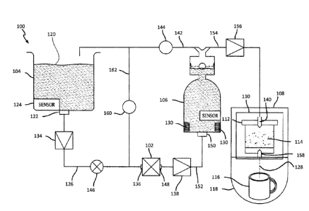
[0031] FIG. I is a schematic view of one embodiment of a beverage system
according to an
aspect of the present disclosure. In an aspect of the present disclosure,
system 100, includes
pump 102 that can be configured to pump unheated fluid, e.g., water, from a
reservoir 104 to a
heater 106, which heats the water to a desired temperature for delivery to a
brew head 108. The
brew head 108 includes a receptacle 110 that can house a cartridge 112
containing a single-serve
or a multi-serve amount of a beverage material 114, e.g., coffee grounds, tea,
hot chocolate,
9
CA 3060750 2019-10-29
lemonade, etc., for producing a beverage dispensed from the brew head 108. The
beverage can
be dispensed into a container 116, e.g., mug, carafe, etc. which can be placed
on a platen 118.
[0032] The reservoir 104 may store fluid 120, e.g., ambient temperature
water, that may be
used to brew a serving and/or multiple servings of beverage (e.g., coffee) in
accordance with the
embodiments and processes disclosed herein. The fluid 120 may exit the
reservoir 104 during the
brew process via an outlet 122 at the bottom of reservoir 104. The fluid 120
may exit the
reservoir 104 from locations other than the bottom, such as the sides or the
top such as via a
reservoir 104 pickup extending down into the reservoir 104, or other locations
as desired or
feasible. In an aspect of the present disclosure, the reservoir 104 includes a
water level sensor
124 and/or other sensors (not shown) to detect whether the reservoir 104 is
sealed by the lid, has
a low water level, or other conditions, and may interact with brewer 100
circuitry to prevent
initiation of a brew cycle in the event there are undesirable conditions
present in brewer 100. The
reservoir 104 may be replaced by other fluid 120 sources, such as a water tap
connection.
[0033] In an aspect of the present disclosure, the pump 102 pressurizes
and/or pumps fluid
120 from the reservoir 104 to the cartridge 112 and/or pumps air to purge
remaining fluid 120
and/or brewed beverage from the beverage system 100. In such an aspect, the
pump 102 initially
pumps fluid 120 from the reservoir 104 through a first conduit 126 to the
heater tank 106 where
the fluid 120 is heated to a predetermined temperature before delivery to the
cartridge 112 to
brew the beverage material 114 into beverage 128. At, near, or after the end
of the brew cycle,
the pump 102 pumps air through the beverage system 100 to purge any remaining
fluid 120 or
beverage 128 in brewing system 100. As such, the pump 102 is able to operate
in both wet and
dry conditions, i.e., the pump 102 can switch between pumping water and air
without undue
wear and tear, although separate pumps for water and air are possible without
departing from the
CA 3060750 2019-10-29
scope of the present disclosure. Many variables exist within brewing system
100 that may affect
the overall performance of brewing system 100. Each of these variables may be
at least partially
accounted for through processor 800 to produce a more consistent performance
in beverage
system 100.
[0034] Once pierced by nozzle 140, each cartridge 112 provides
resistance to the flow of
fluid through cartridge 112 to mug 116. This resistance varies based on, among
other things, the
beverage medium within cartridge 112. For example, and not by way of
limitation, bouillon
within cartridge 112 may provide less resistance to fluid flow than ground
coffee, because
bouillon dissolves in the heated fluid 120 from nozzle 140 while coffee
grounds do not.
[0035] The pressure drop across the beverage material 114 can
result in back pressure
against the outlet of check valve 132. If this back pressure is high enough
(e.g., equal to or
greater than the difference in pressure between the inlet and outlet of the
check valve 132), check
valve 132 may close, or cartridge 112 (or filter paper that is internal to
cartridge 112) may be
= "blown out" by the pressure created by the incoming pressure of the
heated fluid through nozzle
= 140.
Cartridge Construction
[0036] FIG. 2 illustrates a beverage cartridge in accordance with
an aspect of the present
disclosure. Cartridge 112 comprises a cartridge body 200, a filter 202, and a
cover 204. Although
current cartridge bodies 200 are made from various types of plastic, in an
aspect of the present
disclosure, cartridge body 200 may comprise of a cellulose-based material.
[0037] Filter 202 is inserted into cartridge body 200 and may be
adhered to cartridge body
200 at ridge 206. Sides 208 of filter 202 may be pleated or otherwise shaped
to fit within a shape
of cartridge body 200. For example, and not by way of limitation, cartridge
body 200 may be
11
CA 3060750 2019-10-29
finstoconical in shape, and filter 202 may be pleated along the sides 208 such
that the top of
filter 202 sides 208 may be adhered to ridge 206 while sides 208 are proximate
the frustoconical
shape of the cartridge body 200. The shape and/or depth of filter 202 allows
for a space 210
("X") to reside between a bottom 212 of cartridge body 200 and bottom 214 of
filter 202. Space
216, ("X-Delta") is the depth to which outlet needle 158 penetrates into
cartridge body 200.
Space 210 is often larger than space 216, to ensure that outlet needle 158
does not pierce filter
202, which would allow beverage material 114 to be delivered out of outlet
needle 158 to mug
116 (as shown in FIG. 1).
[0038] Cover 204 is adhered to rim 218 with adhesive 220. Adhesive 220, and
adhesive 222
used to adhere filter 202 to cartridge body 200, may be a sonic welding
adhesion, and/or an
adhesive material, which couples cover 204 to cartridge body 200. Cover 204
provides a
substantially air-tight seal such that beverage material 114 is not exposed to
air, which may
oxidize beverage material. Further, cover 204, when adhered to cartridge body
200, may allow
for an inert gas, such as nitrogen, to be contained within cartridge 112 to
further reduce oxidation
and/or other degradation of beverage material 114 between the time beverage
material 114 is
packaged in cartridge 112 and used in brewing system 100. Such a reduction in
degradation of
beverage material 114 may improve the flavor and/or consistency of beverage
128 produced in
brewing system 100.
Cartridge Body Material
[0039] Cartridge 122, and in particular cartridge body 200, is often made
from plastic. Plastic
materials may be categorized to by their "recycling number" which is often
stamped or otherwise
imprinted on plastic materials to indicate the type of plastic used in making
a specific container.
Depending on the recycling number, plastic materials may or may not be
recyclable.
12
CA 3060750 2019-10-29
[0040] Plastic #1, Polyethylene Terephthalate (sometimes referred
to as "PETE" or "PET"),
is often clear or transparent and used to make soda and/or water bottles.
Plastic #2, High Density
Polyethylene, (sometimes referred to as "HDPE") is often opaque, and may be
used to
manufacture milk jugs, household cleaner containers, juice bottles, shampoo
bottles, and box
liner bags. Plastic #3, vinyl (also known as polyvinylchloride, or referred to
as "V" or "PVC"),
may be used in food wrapping materials, plumbing pipes, and detergent bottles.
Plastic #4, Low
Density Polyethylene (sometimes referred to as "LDPE") may be found in
squeezable bottles,
shopping bags, and/or food wrapping materials.
[0041] Plastic #5, Polypropylene (also referred to as "PP" or
"polypro") may be used in
making yogurt containers, and/or food packaging bottles. Plastic #6,
Polystyrene (sometimes
referred to as "PS" or "Styrofoam") may be found in compact disc cases, egg
cartons, meat trays,
and/or disposable plates and cups. Plastic #7 is a "miscellaneous" category,
where plastic resins
= or mixtures of plastic resins that do not fit into categories 1-6 are
placed. Plastic #7 may include
polycarbonates, and may be used to manufacture sunglasses, computer cases,
nylon, and/or other
= goods.
[0042] Depending on the material used to manufacture cartridge
body 200, cartridge body
200 may be recyclable. Although all plastics are theoretically recyclable,
many curbside
recycling programs will not accept some plastics, e.g., plastic #6, plastic
#7, etc., as recyclable
materials.
[0043] Further, some plastics may contain chemicals that may leach
from the body 200
material under certain conditions. For example, plastic #3 may contain Bis(2-
ethylhexyl) adipate,
or DEHA. DEHA has been demonstrated to induce liver adenomas and carcinomas in
mice, and
many people consider DEHA to be a human health risk. As another example,
plastic #7 may
13
CA 3060750 2019-10-29
contain bisphenol-A (BPA). BPA is also potentially toxic in humans, as BPA is
considered to be
a hormone disruptor linked to infertility, hyperactivity, reproductive
problems, and other health
issues.
[0044] Depending on the brewing system 100, several different beverages 128
may be
produced. Many brewing systems are able to recognize differences in cartridge
112 to change the
brewing conditions, including brewing time, temperature, and pressure. To brew
coffee, for
example, fluid 120 may be heated to 190 F and introduced into cartridge 112
for several
minutes at a lower pressure. For espresso-style beverages 128, fluid 120 may
be heated to
approximately 210 F and introduced into cartridge 112 for a shorter period of
time at a higher
pressure. Some brewing processes may include fluid 120 temperatures above 212
F when steam
is injected through nozzle 140. These time, temperature, and pressure
variables may also be user-
selected. As such, cartridge 112, and thus cartridge body 200, may be exposed
to a range of
temperatures and pressures, and the range of temperatures and pressures may or
may not be
known prior to cartridge body 200 use. Further, such temperatures and/or
pressures may cause
degradation of the cartridge body 200 plastic material, resulting in
distortion of the cartridge
body 200 shape and/or release of leached materials from the cartridge body 200
into the
beverage 128.
[0045] Cellulose-based materials that may be employed for the cartridge
body 200 in an
aspect of the present disclosure include, but are not limited to, recycled
paper, paper, organic
materials such as plants, etc., and other materials. Such materials may
include binding material,
such as starches, glue, etc., and/or materials that increase the ability of
cartridge body to
withstand the conditions of brewer 100.
14
CA 3060750 2019-10-29
[0046] FIG. 3 illustrates a method for recycling a beverage cartridge as
described in the
related art. As shown in FIG. 3, a process 300 for recycling K-cup cartridges
112 (also known
as "pods") is illustrated. Block 302 indicates that cover 204 should be peeled
from cartridge body
200 after cartridge 112 has cooled. Cover 204 is grasped by the puncture
(hole) in cover 204
made by inlet nozzle 140 and removed from cartridge body 200. Cover 204 is to
be disposed
after removal.
[0047] In block 304, beverage material 114 is to be emptied from cartridge
body 200.
Beverage material 114 may be composted or disposed of. Filter 202 (not shown
in FIG. 3) is
described as remaining in cartridge body 200.
[0048] In block 306, cartridge body 200 is described as being made from
Plastic #5, which is
polypropylene, and can be recycled once cover 204 is removed and beverage
material 114 is
emptied out of cartridge body 200.
[0049] However, the related art as shown in FIG. 3 does not provide a time-
effective and/or
method for recycling cartridge body 200. The user must remove the cover 204
from a hole that is
approximately 0.2 inches in diameter, which is inconvenient, and remove the
beverage material
114 separately. Further, the cover 204 is difficult to remove from the
cartridge body 200 in a
single piece, since the user will likely tear out a section of cover 204 from
the puncture towards
the edge of cover 204. Having to remove the beverage material 114 separately
from the cover
merely adds to the inconvenience of the related art method.
[0050] Further, and perhaps more importantly, the related art method does
not address the
decomposition of cartridge body 200 during the operational conditions of
beverage system 100.
Current cartridge body 200 materials, which are plastic #7, may deform from
their original
thermoplastically-set shape when exposed to fluid 120 at 205 F. Plastic #5,
which may have a
CA 3060750 2019-10-29
higher melting point than plastic #7, still may leach materials into beverage
128. Nothing is
mentioned in the related art about binders and/or fillers that may be included
in plastic #5 when
used in cartridge body 200, and how these binders and/or fillers may also be
leached into
beverage 128.
[0051] The physical processes that occur during thermal decomposition of
polymers and/or
plastics depends at least in part on the material being used. Further,
thermosetting and
thermoplastic materials do not often have a well-defined phase transformation
at a specified
temperature. Instead, thermoplastic and thermosetting materials have a second-
order transition
between solid and liquid phases.
[0052] For example, and not by way of limitation, thermosetting and
thermoplastic materials
do not have a single transition curve. Polypropylene (Plastic #5) is 65%
crystalline, and has a
crystalline melting temperature of 170 degrees Centigrade. Because
polypropylene is not 100%
crystalline, it is considered as partially amorphous and, thus, is a fluid
that, over periods of time,
will flow into different shapes and has internal flow within the structure,
even at room
temperatures. This characteristic of polypropylene, and/or other thermosetting
and thermoplastic
materials, is similar to window glass, as both materials are amorphous.
[0053] For amorphous and/or semi-amorphous materials, the transition from a
glass state to a
soft and/or malleable state is called the glass-transition region, and begins
occurring at a
temperature known as the glass transition temperature. This property of
thermoplastic materials
is what allows these materials to be formed through the use of heat, and then
cooled to the point
where they are rigid and in the desired shape. As an example, the cartridge
body 200 may begin
as a flat sheet of plastic, but is formed into the frustoconical shape of the
cartridge body 200 by
addition of heat and/or pressure to form the shape of cartridge body 200.
Depending on the
16
CA 3060750 2019-10-29
binding and/or filler materials used, the "polypropylene" material may have a
large number of
transition curves and thus leach at different rates for a given temperature.
[0054] Many materials also desorb adsorbed fluids (e.g., water) at elevated
temperatures.
The activation energy for physical desorption of water is 30 ¨40 kilojoules
(kJ) per mol, and
desorption begins occurring at temperatures below 212 F. Polypropylene has a
glass transition
temperature of negative 4 (-4) F. This means that at room temperature
polypropylene has
internal fluidic migrations of materials, i.e., the 35% of material in
polypropylene that is not
crystalline, even though these migrations are not visible to the human eye.
[0055] Further, when cartridge body 200 is exposed to the operational
conditions of brewing
system 100, cartridge body 200 may be in direct contact with fluid 120 at
temperatures between
145-212 F for several minutes. The fluidic motion of the non-crystalline
materials within
cartridge body 200, as well as the crystalline polypropylene itself, and/or
any fillers and/or
binders used in cartridge body 200, would thus be raised even further above
the glass transition
temperature, and become fluid in the classical sense. The fluid 120 is also
pressurized against the
cartridge body 200, and the combination of pressure and temperature conditions
present in
brewing system 100 may create leaching of some of the cartridge body 200
material and/or the
fillers and/or binders present in the cartridge body 200 material into
beverage 128.
[0056] FIG. 4 illustrates a cross-sectional view of a single-serve beverage
cartridge in
accordance with an aspect of the present disclosure. In FIG. 4, filter 202 may
be attached to
cover 204 by adhesive 400. Cover 204 may also be made of a cellulose-based
material, and may
be made of a different cellulose-based material than cartridge body 200
without departinf from
the scope of the present disclosure. Portion 402 of filter 202 is then coupled
to rim 218 of
cartridge body 200, rather than being coupled to ridge 206. This may simplify
the manufacture of
17
CA 3060750 2019-10-29
cartridge 112, as filter 202 may be coupled to cover 204 prior to attachment
of the then combined
filter 202/cover 204 to cartridge body 200. For example, and not by way of
limitation, beverage
material 114 may be sandwiched in a pod comprising filter 202 and cover 204
(as well as other
layers of material if desired), and these pods may then be coupled to rim 218
of cartridge body
200. As long as the bottom 214 of filter 202 would not be pierced by needle
158, the attachment
of filter 202 to cover 204 rather than to the ridge 206 of cartridge body 200
is not critical to the
operation of cartridge 112 in beverage system 100.
[0057] Because single-serve cartridges 112 are designed to be
pierced on the bottom 212 of
cartridge body 200, filter 202 is designed to hold beverage material 114 above
the level of the
needle 158 at all locations. If cartridges 112 were designed to be pierced on
the cover 204 for
= both the inlet nozzle 140 and the outlet needle 158, filter 202 would
have no such restriction for
= having a bottom 214 that sits a distance 210 away from bottom 212. Some
cartridges that may be
used for multi-serve brewing, such as K-carafe cartridges, are designed to be
pierced on the
cover by a second needle for delivering the beverage 128 to mug 116 and are
not pierced on the
bottom by outlet needle 158. Such cartridges are not considered single-serve
cartridges 112, and
are not compatible with all brewing systems 100 in the single-serve brewing
market. Further,
such multi-serving and/or multi-serve cartridges have not been as well
accepted in the
marketplace as the single-serve cartridges 112 that are pierced on the bottom
212 of cartridge
body 200, because the multi-serve cartridges are less convenient than the
single-serve cartridges
112. However, such multi-serve cartridges are also considered to be "single-
serve" cartridges
112 for the purposes of this disclosure.
[0058] Adhesive 400 may be the same adhesive material as adhesive
220, or may be a
different adhesive depending on the materials used in filter 202, cover 204,
and cartridge body
18
CA 3060750 2019-10-29
200, and/or other considerations as desired. In an aspect of the present
disclosure, cover 204 may
include tab 404, which extends beyond an outer circumference of rim 218 of
cartridge body 200.
Tab 404 provides a gripping surface for cover 204, such that cover 204 may be
removed from
rim 218, rather than attempting to pull cover 204 away from rim 218 via a
pierced hole as
described with respect to FIG. 3.
10059] Since cover 204 is now coupled to filter 202, pulling tab 404 may
separate filter 202
and cover 404 from cartridge body 200 together, rather than leaving filter 202
in cartridge body
200 as described with respect to FIG. 3. Further, because filter 202 and cover
404 are coupled
together, either via adhesive 400 and/or by other methods, beverage material
114 is contained
within the combination of filter 202 and cover 204. In many beverage systems
100, beverage
material 114 has been purged of most of the fluid 120 used to brew beverage
128 by pumping air
through beverage material 114, so removing beverage material 114 along with
filter 202 and
cover 204 is easier to perform than the method described in FIG. 3.
[0060] In a further aspect of the present disclosure, filter 202 may be
made from a
biodegradable material, compostable material and/or cellulose-based material.
Cover 204 may
also be made from a biodegradable material, compostable material and/or
cellulose-based
material. For example, and not by way of limitation, filter 202 may be made
from paper, and
cover 204 may be made from a biodegradable plastic or plant-based material. As
such, the
combination of filter 202, cover 204, and beverage material 114 may be
entirely biodegradable,
compostable, and/or recyclable. Once separated from cartridge body 200, the
combination of
filter 202, cover 204, and beverage material 114 may then be used as compost,
while cartridge
body 200 may then be recycled as plastic and/or other compostable material
such as paper. Such
19
CA 3060750 2019-10-29
an approach is far simpler, and far more environmentally-friendly, than the
related art approach
of FIG. 3.
[0061] In another aspect of the present disclosure, filter 220 may comprise
tab 406, either
alternatively or in conjunction with tab 404 of cover 204. Tab 406 allows for
filter 202 to be
pulled or otherwise separated from cartridge body 200 when the combination of
filter 202, cover
204, and beverage material 114 are removed from cartridge body 200. Tabs 404
and/or 406 may
provide additional strength to the bond, connection, and/or coupling between
filter 202 and cover
204, and an additional means for providing force to remove the combination of
filter 202, cover
204, and beverage material 114 from cartridge body 200.
[0062] FIGS. 5 and 6 illustrate exploded perspective views of a single-
serve beverage
cartridge in accordance with an aspect of the present disclosure. Cartridge
112 is shown with
cover 204, filter 202, and cartridge body 200. Tabs 404 and 406 are shown,
however, as
described above, aspects of the present disclosure may have only one of such
tabs 404 and/or
406 present as desired. Sides 208 of filter 202 are shown as being pleated in
FIG. 5, although
such pleating is optional in any aspect of the present disclosure.
[0063] A location where inlet nozzle 140 may pierce cover 204 is shown as
location 500.
Cover 204 may be coupled to filter 202 as shown by arrow 502. This may make a
combined unit
504, which may then be inserted into cartridge body 200 as shown by arrow 506.
As shown in
FIG. 6, part of filter 202, i.e., portion 402, may overlap rim 218. As cover
204 is coupled to filter
202, either as shown by arrow 600 or as a unit 504 described with respect to
FIG. 5, cover 204 is
coupled to rim 218 of cartridge body 200. Tabs 404 and/or 406 may be used to
remove filter 202
and cover 204 from cartridge body 200 while allowing filter 202 and cover 204
to substantially
remain coupled together.
CA 3060750 2019-10-29
[0064] FIG. 7 illustrates a cross-sectional view of a single-serve beverage
cartridge in
accordance with an aspect of the present disclosure. As with FIG. 4, filter is
not coupled to ridge
206 as in the related art. In the aspect of the present disclosure shown in
FIG. 7, a liner 700 is
placed between the inner surface of cartridge body 200 and filter 202. Liner
700 may comprise
tab 702, which may be used alone or in conjunction with tabs 404 and 406 as
described with
respect to FIG. 4.
[0065] Liner 700 limits the direct contact between fluid 120 that is
introduced into cartridge
112 and cartridge body 200. Because cartridge body 200 may leach chemicals
and/or other
materials into beverage 128, and be delivered via needle 158, liner 700
reduces the possibilities
that such leaching will occur. Although heated fluid 120 will still likely
leach material from
cartridge body 200 through thermal exchange with cartridge body 200, liner 700
reduces and/or
eliminates the pathways for such leached material from exiting cartridge 112
through needle 158
as part of beverage 158. Although liner 700 is shown as being substantially
similar in shape to
cartridge body 200, e.g., conforming to the side and bottom of cartridge body
200, liner 700 may
take any shape as desired that limits the contact between fluid 120 and the
inner wall of cartridge
body 200.
[0066] FIG. 8 illustrates a controller in accordance with an aspect of the
present disclosure.
The brewer 10 can include a controller or other processing unit, such as a
microcontroller 800,
shown schematically in FIG. 8. The microcontroller 800 may include an internal
memory 802
and/or external memory 804 and can serve many different functions. For
example, in one
embodiment, the microcontroller 102 may serve to regulate the power provided
to the pump 102,
control system 100 through readings from sensor 124 and/or other sensors
within system 100,
21
CA 3060750 2019-10-29
accept input from user controls 806, or other controlling and/or monitoring
functions. Many
different functions are possible without departing from the scope of the
present disclosure.
[0067] The memory, which may be internal memory 802 or external memory 804
to
microcontroller 800, may be implemented in firmware and/or software
implementation. The
firmware and/or software implementation methodologies may be implemented with
modules
(e.g., procedures, functions, and so on) that perform the functions described
herein. A machine-
readable medium tangibly embodying instructions may be used in implementing
the
methodologies described herein. For example, software codes may be stored in a
memory and
executed by a processor unit (e.g., microcontroller 800). Memory may be
implemented within
the processor unit or external to the processor unit. As used herein, the term
"memory" refers to
types of long term, short term, volatile, nonvolatile, and/or other non-
transitory memory and is
not to be limited to a particular type of memory or number of memories, or
type of media upon
which memory is stored.
[0068] FIGS. 9A and 9B illustrate a recyclable beverage cartridge in
accordance with an
aspect of the present disclosure. FIG. 9A shows filter 900 located at a
distance 900 from side 208
of the cartridge body 200. Distance 902 is a known distance, and may be
approximately 0.25
inches, because cartridge body 200 is designed to fit within receptacle 110 in
any orientation,
and the outlet needle 158 is in a fixed location within receptacle 110. As
such, a toroidal volume
may be defined by filter 900, having a height at least as high as dimension
216, with a tolerance
for the location of the toroid such that filter 900 is not pierced and/or
otherwise compromised by
needle 158 when needle 158 pierces cartridge body 200.
[0069] Further, cartridge body 200 may be made from paper, pulp, cellulose
and/or celluloid
material, plant fibers, or other natural, renewable, recyclable, and/or
compostable products, such
22
CA 3060750 2019-10-29
that once the cartridge 112 has been used (i.e., nozzle 140 has pierced cover
204 and delivered
fluid to cartridge 112 and beverage material 114 to brew a beverage 128), the
entire cartridge
112 may be placed in a compost pile rather than separating cover 204 from
cartridge body 200.
As shown in FIG. 9B, filter 900 covers a cylindrical volume within cartridge
112, such that
regardless of the orientation of cartridge 112 when placed in system 100,
outlet nozzle 158 will
pierce bottom 212 of cartridge 112 on one side of filter 900 while beverage
material 114 is on an
opposite side of filter 900.
[0070] In an aspect of the present disclosure, cartridge body 200 may be
made from wood
pulp and/or recycled paper products, which may be combined with food-safe
binders such as
starches and/or sugars, and/or other adhesives and/or binders that are safe
for interactions with
consumed products. To minimize leaching of flavors or other possibly
undesirable liquids and/or
solids from cartridge body 200 in such cases, an optional liner 904, which may
be made of a
different material than cartridge body 200, e.g., metal foil, a different
natural, plant, and/or
combination of materials, and/or may have a different density than cartridge
body 200, such that
contact between fluids entering cartridge 112 and cartridge body 200 are
reduced when
compared to cartridges 112 that do not include optional liner 904. Optional
liner 904 may further
comprise an optional portion 906 and/or optional tab 908 without departing
from the scope of the
present disclosure. The inclusion of liner 904 may minimize and/or prevent
seepage of any
flavors, binders, and/or other by-products from cartridge body 200, similar to
how liner 700
minimizes leaching of by-products when cartridge body 200 is made from
plastic.
[0071] Liners 700 and/or 900 may be made from various materials; metal
foil, plastic, paper,
natural materials, etc. Liners 700 and/or 900 may provide several advantages
and/or functions to
cartridge 112. For example, and not by way of limitation, liner 700 and/or 900
may provide a
23
CA 3060750 2019-10-29
hermetic and/or semi-hermetic seal for a portion of cartridge 112, such that
beverage material
114 contained within cartridge 112 is substantially separated from outside air
and/or other
contaminants or oxidizing materials. Depending on the material used for
cartridge 112, cartridge
112 may already provide a hermetic and/or semi-hermetic seal. Further, and not
by way of
limitation, liner 700 and/or 900, either in addition to or in the alternative,
may provide a barrier
between any liquid introduced into cartridge 112 and the cartridge body 200,
such that the liquid
introduced into cartridge 112 does not substantially contact cartridge body
200. Such liners 700
and/or 900 may also prevent any liquids, gasses, or fluids produced by the
heat, pressure, and/or
other operational conditions within beverage system 100 that are experienced
by cartridge 112
from being delivered to mug 116 along with beverage 128.
[0072] FIGS. 10 and 11 illustrate filter designs in accordance with an
aspect of the present
disclosure. Filter 900 may take any shape desired, and, as shown in FIG. 10,
may be conical in
shape rather than adopting the frustoconical shape of cartridge body 200 as
shown in FIGS. 2
and 4-7. So long as filter 900 is not pierced by needle 158, filter 900 may
take any desired shape,
which may alter the brewing considerations and/or possibilities for various
beverage materials
114. For example, and not by way of limitation, allowing filter 900 to reach
the bottom of
cartridge body 200, either as a conical shape shown in FIG. 10 or as a stepped
frustoconical
shape shown in FIG. 11, fluid introduced into cartridge 112 will remain in
contact with beverage
material 114 present for a longer period of time before being delivered to mug
116 via needle
158. Further, a different type of beverage material 114 may be placed in
volume 910, which may
also be separated from beverage material 114 by a second filter, to produce a
hybrid-brewed
beverage of the two beverage materials 114 present in cartridge 112. Such
combinations and/or
time duration of fluid/beverage material 114 contact differences are not
possible in the related
24
CA 3060750 2019-10-29
art, as the time duration is driven by fluid flow rates determined by pump
102. By allowing fluid
from inlet nozzle 140 to remain in contact with beverage material 114 for a
longer period of
time, additional and/or other oils, flavors, and/or essences may be removed
from beverage
material 114 without requiring design changes to beverage system 100 or
programming pump
102 to deliver fluid to nozzle 140 at different rates.
Craft Brewing Techniques
100731 FIG. 12 illustrates a beverage cartridge in accordance with an
aspect of the present
disclosure. Cartridge 112 may also comprise a mechanism 1200 that may move,
tighten, loosen,
or otherwise interface with beverage material 114 once inlet nozzle 140 is
inserted into cartridge
112. Some systems 100 have inlet nozzles 140 that move and/or rotate after
piercing cover 204.
Depending on the settings and/or programming of such systems 100, inlet nozzle
140 can rotate
in one direction for a first set of settings, and a second direction for a
second set of settings. As
such, mechanism 1200 may be selectively engaged by inlet nozzle 140 based on
the direction of
movement and/or rotation of inlet nozzle 140.
100741 For example, and not by way of limitation, inlet nozzle 140 may
comprise a tab 1202
that only engages mechanism 1200 when inlet nozzle 140 rotates in a clockwise
direction. One
side of tab 1202 may provide a surface that mechanism 1200 catches on and
tightens when inlet
nozzle 140 rotates in a clockwise direction, while another side of tab 1202 is
a ramp or incline
that will not engage mechanism 1200 when inlet nozzle 1200 rotates in a
counter-clockwise
direction. System 100 may allow for user input or automatic selection based on
recognition
and/or other identification of cartridge 112 to program the inlet nozzle 140
to rotate clockwise,
which will allow tab 1202 to engage mechanism 1200 during brewing, or may
allow for user
input to program the inlet nozzle 140 to rotate counter-clockwise, which will
avoid engagement
CA 3060750 2019-10-29
of mechanism 1200 during brewing. Other types of engagement between inlet
nozzle 140 and
mechanism 1200 are possible without departing from the scope of the present
disclosure.
[0075] If mechanism 1200 is engaged, a first set of conditions, such as
pressure, temperature,
volume, etc., for beverage material 114 will be created by mechanism 1200. If
mechanism 1200
is not engaged, a second set of conditions for beverage material 114 is
created, which may be
similar to the set of conditions created by system 100 when mechanism 1200 is
not present
within cartridge 112.
[0076] Mechanism 1200, which is shown as a torsion spring, but may be any
mechanism,
may provide conditions for brewing that system 100 could not otherwise attain.
For craft coffee
beverages, e.g., "French press" coffee, "pour over" coffee, etc., system 100
may not be able to
provide the pressure conditions within cartridge 112 without the use of
mechanism 1200. If
mechanism 1200 is not engaged, system 100 would produce a beverage similar to
if not identical
to the beverage produced if mechanism 1200 is not present. However, if
mechanism 1200 is
engaged during brewing, different pressures, localized temperatures, reduced
volumes, etc., may
produce a different beverage from the same cartridge 112.
[0077] Although mechanism 1200 is shown as a torsion spring, other
mechanisms are
possible within the scope of the present disclosure. Further, beverage
material 114 may be
located at specific locations within cartridge 112, such as along the side
208, along the bottom
212, etc., such that the combination of type of mechanism 1200 and placement
of beverage
material 114 within cartridge 112 provides operational advantages within
system 100.
[0078] For example, and not by way of limitation, mechanism 1200 may
provide additional
pressure to beverage material 114 when mechanism 1200 is engaged by inlet
nozzle 140. System
100 may be programmed to introduce fluid to cartridge 1200 for a certain
amount of time and
26
CA 3060750 2019-10-29
then stop introducing fluid. System 100 may then allow the fluid to drain from
cartridge 112 for
a certain amount of time, and then engage mechanism 1200 to pressurize the
added fluid out of
cartridge 112 through outlet needle 158. System 100 may then add more fluid to
cartridge 112
and repeat these steps. Such an approach is similar to a "pour over" style of
coffee brewing.
Similar mechanisms 1200, beverage material 114 placement, and/or fluid
delivery techniques
may be combined to produce other types of brewing techniques in system 100.
Such techniques
are not currently employed in related systems 100.
Variable Porosity and Flavor Additives
[0079] FIG. 13 illustrates a beverage cartridge in accordance with an
aspect of the present
disclosure. Cartridge 112 may comprise a filter 1300 which has a variable
porosity. A portion
1302 of filter 1300 may have a first porosity value, while portion 1304 of
filter 1300 may have a
second porosity value. As such, fluid introduced into cartridge 112 may remain
in portions of
filter 1300 longer than in other portions of filter 1300.
[0080] For example, and not by way of limitation, portion 1302 may be less
porous than
portion 1304. As such, fluid 120 that is introduced into cartridge 112 will
not flow through
portion 1302 as fast, or at all, as fluid 120 that reaches the level of
portion 1304. This may
increase the time that fluid remains in contact with beverage material 114
that is contained
within portion 1302. As the fluid level rises in cartridge 112, fluid 120 will
flow out of portion
1304. This allows for more precise control of the time that fluid 120 remains
in contact with
beverage material 114. Through programming of system 100, e.g., fluid delivery
flow rate, fluid
delivery temperatures, etc., more precise brewing profiles may be achieved
with system 100
through the use of variable flow rate filter 1300.
27
CA 3060750 2019-10-29
[0081] Further, to allow for increased pressure within cartridge 112 when
employed in
system 100, cover 204 may be wrapped around rim 218 and adhered to a larger
surface of rim
218. The cartridge body 200 may be placed in a receptacle that allows for only
small amounts of
expansion of the cartridge body 200. In many cartridge 112 designs, the
sealing surface of cover
204 to cartridge body 200 along rim 218 is the location of pressure blowouts
experienced by
cartridge 112. As such, increasing the pressure and force vectors that may be
experienced at that
location by encasing rim 218 with cover 204, and applying adhesive 400 to a
larger surface of
rim 218 (e.g., on both sides of rim 218), allows for greater pressure to be
applied within cartridge
112 with fluid 120.
[00821 In an aspect of the present disclosure, cartridge body 200 may have
a textured
surface, specific color, other identifying marks, and/or indicia 1320 such
that brewer 100 may
recognize cartridge 112 as a specific type of cartridge 112. This recognition
may be used to
determine brewing characteristics, for rewards programs, and/or for any other
reason. However,
some users may try to use the same cartridge 112 several times to obtain
additional rewards, or
may accidentally attempt to reuse a cartridge 112. Because cartridge body 200
may be made
from cellulose-based materials, and cartridge 112 may be placed under pressure
when fluid 120
is delivered to cartridge 112, the pressure and/or water temperature may
soften cartridge body
200. The pressure created by brewer 100 in delivering fluid 120 to cartridge
112 may allow for
deformation of the surface of cartridge body 200. Further, the fluid 120,
after passing through
beverage material 114 and becoming beverage 128, may change the color of
cartridge body 200.
As such, the use of a given cartridge 112 in brewer 100 may alter and/or
otherwise change the
indicia 1320 such that the indicia 1320 no longer indicates the same
information to brewer 100.
Such changes in the indicia 1320 will allow brewer 100 to minimize reuse of
the same cartridge
28
CA 3060750 2019-10-29
112, by alerting the user to reuse of a given cartridge 112, and/or minimize
the recognition of
cartridge 112 multiple times in rewards and/or accounting functions performed
by brewer 100.
Although indicated at a certain location on cartridge 112, indicia 1320 may
appear anywhere on
cartridge 112 without departing from the scope of the present disclosure.
100831 Many cartridges 112 have added flavors and/or essences
infused into beverage
material 114. For example, some coffee beverages have hazelnut or caramel
flavors infused or
= added to the beverage material 114. The process of infusing such flavors
into beverage material
= 114 may add to the cost of cartridge 112, and/or the beverage material
114 may be degraded or
otherwise altered by the infusion process. In an aspect of the present
disclosure, materials 1306
and/or 1308 may be added to and/or infused into cartridge body 200, which may
provide a more
economical approach to inclusion of various additives in cartridge 112.
[00841 For example, and not by way of limitation, an essential oil
may be added to cartridge
body 200 at location 1506 and/or infused into a portion of or all of cartridge
body 200. Since
cartridge body 200 in an aspect of the present disclosure is cellulose-based,
and is manufactured
using oils and/or other binders, the infusion process may be less expensive
than infusion of the
same essential oil into beverage material 114. Further, infusion of the
essential oil into cartridge
body 200 may have fewer deleterious effects on beverage material 114 as well
as fewer
deleterious effects on the essential oil. A smaller amount of essential oil
may be needed to
provide the same flavors and/or other effects in the resultant beverage by
placing the essential oil
at location 1306 and/or 1308 than with beverage material 114.
[0085] Filter 1300 may also have a specialized shape 1310. Shape
1310 may accommodate
inlet nozzle 140, or may be shaped to control one or more process parameters
used during and/or
after the brewing process. For example, and not by way of limitation, shape
1310 may be used to
29
CA 3060750 2019-10-29
control the amount of time that fluid remains in contact with beverage
material 114. Many
shapes 1310 can be employed without departing from the scope of the present
disclosure.
[0086] FIG. 14 illustrates a beverage cartridge in accordance with an
aspect of the present
disclosure. Some cartridges 112 do not have a body 200 that fully encloses the
beverage material
114. Such cartridges 112 may be referred to as "soft pods." One drawback of
soft pods is that the
beverage material 114 may be exposed to air or other oxidizing environments,
which may
deleteriously affect the beverage material 114.
[0087] In an aspect of the present disclosure, cartridge 1400 may be
designed to have a
separation line that exposes filter 1300. When placed in the system 100,
cartridge 1400 has a
cartridge body 1402 that separates from separated portion 1404 when fluid is
introduced into
cartridge 1400. The additional pressure introduced into cartridge 1400 by
fluid 1400 may provide
separation between cartridge body 1402 and separated portion 1404 such that
the body 1402 and
separated portion 1404 separate along upper separation line 1406 and lower
separation line 1408.
Separated portion 1404 moves away from body 1402 in direction 1408.
[0088] The upper and lower separation lines 1406/1408 may be a perforation
line on
cartridge 1400. Since the pressure in system 100 may be controlled, the
pressure system 100
produces can be controlled to separate cartridge 1400 into body 1402 and
separated portion
1404. Filter 202 may couple body 1402 and separated portion 1404, or separated
portion 1404
may not completely separate from body 1402. So long as pressure is released by
the separation
of body 1402 and separated portion 1404, fluid entering cartridge 1400 will
flow through filter
202 once separated portion 1404 has separated from body 1402. In such an
aspect of the present
disclosure, cartridge 1400 may provide better protection of beverage material
114 than a soft
pod, and may further reduce the cost of production of cartridge 1400.
CA 3060750 2019-10-29
[0089] The present disclosure provides several advantages over the related
art approaches.
The present disclosure allows for easy separation of compostable and
recyclable materials. The
present disclosure also allows for safer operation of beverage systems 100
that employ cartridges
112, in that possible unwanted by-products produced by cartridge 112 during
the operation of
beverage system 100 are not produced and/or consumed.
[0090] Further, the present disclosure allows for different types of
filtration of beverage
material 114, which may be desirable depending on the volume of beverage 128
to be produced
from beverage material 114 in cartridge 112. The present disclosure also
allows for additional
types of beverages 128 to be produced, as well as allowing for richer, more
flavorful beverages
to be produced by currently deployed beverage systems 100. The present
disclosure also
provides upgrades to single-serve beverage systems 100 which may enable these
systems to
employ brewing methods, such as craft brewing methods, that present systems
100 cannot
accommodate.
[0091] If implemented in firmware and/or software, and/or as part of
microcontroller 800
and/or memory 802/804, the fiinctions described herein may be stored as one or
more
instructions or code on a computer-readable medium. Examples include computer-
readable
media encoded with a data structure and computer-readable media encoded with a
computer
program. Computer-readable media includes physical computer storage media. A
storage
medium may be an available medium that can be accessed by a computer. By way
of example,
and not limitation, such computer-readable media can include RAM, ROM, EEPROM,
CD-
ROM or other optical disk storage, magnetic disk storage or other magnetic
storage devices, or
other medium that can be used to store desired program code in the form of
instructions or data
structures and that can be accessed by a computer (e.g., microcontroller 800);
disk and disc, as
31
CA 3060750 2019-10-29
used herein, includes compact disc (CD), laser disc, optical disc, digital
versatile disc (DVD),
floppy disk and 131u-ray disc where disks usually reproduce data magnetically,
while discs
reproduce data optically with lasers. Combinations of the above should also be
included within
the scope of computer-readable media.
[0092] In addition to storage on computer readable medium, instructions
and/or data may be
provided as signals on transmission media included in a communication
apparatus. For example,
a communication apparatus may include a transceiver having signals indicative
of instructions
and data. The instructions and data are configured to cause one or more
processors (e.g.,
microcontroller 800) to implement the functions outlined in the claims.
[0093] Those of skill would further appreciate that the various
illustrative logical blocks,
modules, circuits, and algorithm steps described in connection with the
disclosure herein may be
implemented as electronic hardware, computer software, or combinations of
both. To clearly
illustrate this interchangeability of hardware and software, various
illustrative components,
blocks, modules, circuits, and steps have been described above generally in
terms of their
functionality. Whether such functionality is implemented as hardware or
software depends upon
the particular application and design constraints imposed on the overall
system. Skilled artisans
may implement the described functionality in varying ways for each particular
application, but
such implementation decisions should not be interpreted as causing a departure
from the scope of
the present disclosure.
[0094] The various illustrative logical blocks, modules, and circuits
described in connection
with the disclosure herein may be implemented or performed with a general-
purpose processor, a
digital signal processor (DSP), an application specific integrated circuit
(ASIC), a field
programmable gate array (FPGA) or other programmable logic device, discrete
gate or transistor
32
CA 3060750 2019-10-29
logic, discrete hardware components, or any combination thereof designed to
perform the
functions described herein. A general-purpose processor may be a
microprocessor, but in the
alternative, the processor may be any conventional processor, controller,
microcontroller, or state
machine. A processor may also be implemented as a combination of computing
devices, e.g., a
combination of a DSP and a microprocessor, multiple microprocessors, one or
more
microprocessors in conjunction with a DSP core, or any other such
configuration.
100951 In one or more exemplary designs, the functions described may be
implemented in
hardware, software, firmware, or any combination thereof. If implemented in
software, the
functions may be stored on or transmitted over as one or more instructions or
code on a
computer-readable medium. Computer-readable media includes both computer
storage media
and communication media including any medium that facilitates transfer of a
computer program
from one place to another. A storage media may be any available media that can
be accessed by
a general purpose or special purpose computer. By way of example, and not
limitation, such
computer-readable media can include RAM, ROM, EEPROM, CD-ROM or other optical
disk
storage, magnetic disk storage or other magnetic storage devices, or any other
medium that can
be used to carry or store specified program code means in the form of
instructions or data
structures and that can be accessed by a general-purpose or special-purpose
computer, or a
general-purpose or special-purpose processor. Also, any connection is properly
termed a
computer-readable medium. For example, if the software is transmitted from a
website, server, or
other remote source using a coaxial cable, fiber optic cable, twisted pair,
digital subscriber line
(DSL), or wireless technologies such as infrared, radio, and microwave, then
the coaxial cable,
fiber optic cable, twisted pair, DSL, or wireless technologies such as
infrared, radio, and
microwave are included in the definition of medium. Disk and disc, as used
herein, includes
33
CA 3060750 2019-10-29
compact disc (CD), laser disc, optical disc, digital versatile disc (DVD),
floppy disk and Blu-ray
disc where disks usually reproduce data magnetically, while discs reproduce
data optically with
lasers. Combinations of the above should also be included within the scope of
computer-readable
media.
[0096] The present disclosure is described herein with reference to certain
embodiments, but
it is understood that the disclosure can be embodied in many different forms
and should not be
construed as limited to the embodiments set forth herein. In particular, the
present disclosure is
described below in regards to certain modules having features in different
configurations, but it
is understood that the present disclosure can be used for many other modules
and/or
configurations. The modules and systems can also have many different shapes
beyond those
described below.
[00971 All physical dimensions, weights, temperatures, etc. in the
description and attached
drawings are exemplary in nature. It is understood that embodiments of the
present disclosure
can have various dimensions/weights/ temperatures/etc. varying from those
shown in the
attached drawings.
[0098] Although the present disclosure and its advantages have been
described in detail, it
should be understood that various changes, substitutions and alterations can
be made herein
without departing from the technology of the disclosure as defined by the
appended claims. It
should also be understood that when a feature or element may be referred to as
being "on"
another element, it can be directly on the other element or intervening
elements may also be
present unless specifically stated otherwise. Furthermore, relative terms such
as "inner", "outer",
"upper", "above", "lower", "beneath", and "below", and similar terms, may be
used herein to
describe a relationship of one element or attribute to another. With regard to
the figures, it is to
34
CA 3060750 2019-10-29
be understood that these terms are intended to encompass different
orientations of the device in
addition to the orientation depicted.
[0099] Moreover, the scope of the present application is not intended to be
limited to the
particular configurations of the process, machine, manufacture, composition of
matter, means,
methods, and/or steps described in the specification. As one of ordinary skill
in the art will
readily appreciate from the disclosure, processes, machines, manufacture,
compositions of
matter, means, methods, and/or steps, presently existing or later to be
developed, that perform
substantially the same function or achieve substantially the same result as
the corresponding
configurations described herein may be utilized according to the present
disclosure. Accordingly,
the appended claims are intended to include within their scope such processes,
machines,
manufacture, compositions of matter, means, methods, and/or steps.
[00100] Although the terms first, second, etc. may be used herein to describe
various
elements, components, regions, and/or sections, these elements, components,
regions, and/or
sections should not be limited by these terms. These terms are only used to
distinguish one
element, component, region, or section from another element, component,
region, or section.
Thus, a first module, element, component, region, or section discussed below
could be termed a
second module, element, component, region, or section without departing from
the teachings of
the present disclosure.
[00101] The description of the disclosure is provided to enable any person
reasonably skilled
in the art to make or use the disclosure. Various modifications to the
disclosure will be readily
apparent to those skilled in the art, and the generic principles defined
herein may be applied to
other variations without departing from the spirit or scope of the disclosure.
Thus, the disclosure
CA 3060750 2019-10-29
is not intended to be limited to the examples and designs described herein but
is to be accorded
the widest scope consistent with the principles and novel features disclosed
herein.
36
CA 3060750 2019-10-29