Note: Descriptions are shown in the official language in which they were submitted.
Docket No.: 205-19
TITLE OF THE INVENTION
SUSTAINABLE ENHANCED OIL RECOVERY OF HEAVY OIL METHOD AND SYSTEM
BACKGROUND OF THE INVENTION
.. TECHNICAL FIELD
The present technology relates to a sustainable enhanced oil recovery of heavy
oil (SEOR)
method and system for use in connection with producing hydrocarbons from a
heavy oil formation
or reservoir using in situ steam and carbon dioxide generation. The heavy oil
formation or reservoir
may have undergone primary production using pressure depletion with or without
sand production,
bottom water drive, top gas drive or by waterflooding.
DESCRIPTION OF THE BACKGROUND ART
Heavy oil production using pressure depletion of the reservoir with and
without sand is
known in the prior art as Cold Heavy Oil Production (CHOP) or Cold Heavy Oil
Production with
Sand (CHOPS). CHOP is the primary production of heavy oil using vertical wells
and/or horizontal
wells. When heavy oil is produced using vertical wells, the oil is produced
with reservoir sand, is
foamy with gas, and reservoir pressure decreases significantly. In the
reservoir, the sand is
extracted through a single, multiple or network conduits know as wormholes.
The oil becomes
foamy with gas in the reservoir and flows into the wormholes then to the
vertical well bore. The
wormholes continue to grow in length towards the higher pressure regions of
the reservoir.
Eventually, the wormholes will be unable to grow further due to significant
reservoir pressure
depletion. The production will have declined significantly to an uneconomic
level resulting in the
shut in of the well. The recoverable amount of oil is usually about only 5-10%
of the original oil in
place. The state of the reservoir is the existence of these wormholes or
conduits, connected gas
saturation of about 6-12% of the pore volume and extremely low reservoir
pressure. Gas saturation
increases to replace the produced oil and sand. Eventually, the reservoir
pressure declines to a low
pressure such that the wells are no longer productive. This is known as CHOP
production with sand
or CHOPS.
Initially in CHOP, the reservoir could be in a pressure range of 4000-8000
kPag with no gas
saturation. With depleted CHOP production, gas saturation increases to 6-12%
and pressure
depletes to less than 1000 kPag.
- 1 -
Date Recue/Date Received 2020-12-02
Docket No.: 205-19
Another method of CHOP production is using horizontal wells with slotted
liners to prevent
sand production. The oil becomes foamy with gas as it flows from the reservoir
into the lower
pressure liner of the well. The reservoir pressure decreases with production.
Likewise, the
production decreases with reservoir pressure to an uneconomic level resulting
in the shut in of the
well. The recoverable amount of oil is usually about only 5-10% of the
original oil in place. The
state of the reservoir is a connected gas saturation of about 6-12% of the
pore volume and extremely
low reservoir pressure. This is known as CHOP production with horizontal wells
and without sand.
After CHOP production, the remaining oil is essentially immobile due to the
low reservoir
pressure, low dissolved or solution gas, and much higher viscosity.
Another method of producing the lower viscosity heavy oil is to use
waterflooding.
Waterflooding involves injecting water into one or more wells, and produce
both oil and water from
nearby one or more wells. Water flows laterally and mostly horizontally from
the injection wells
dragging some heavy oil with it to the producing wells. Some of the injected
water could channel to
the producing wells. The injected water and the dragged heavy oil is produced
from the producing
wells. Waterflooding can also occur naturally when the heavy oil is underlain
by a water aquifer.
In this situation, the bottom water pushes the oil upwards to the producing
well and causes water
cones to form. There is also another situation where there is a gas zone above
the oil. The top gas
will push the oil downwards to the producing well and causes gas cones to
form. In all these
situations, water or gas production increases and oil production will decrease
to an uneconomic
level resulting in the shut in of the well.
The ultimate recovery of heavy oil using waterflooding usually amounts to 10-
25% of the
original oil in place.
An enhanced oil recovery method that can be added to horizontal waterflooding
is chemical
flooding. These chemicals are alkaline, surfactant or polymers or ASP. These
chemicals can be
.. added singularly or in combination. This method can increase recovery level
by 5-10% of original
oil in place.
Where the reservoir thickness of the heavy oil is well above 10 meter, thermal
production
method using steam injection can be economic. These thermal methods are known
as steam
flooding, cyclic steam stimulation or Steam Assisted Gravity Drainage (SAGD).
The SAGD
method can be enhanced using solvent and is known as solvent SAGD. These
thermal production
methods are disadvantaged with high costs, emissions of carbon dioxide and
other oxides to the
atmosphere and the need of make-up water for steam generation.
- 2 -
Date Recue/Date Received 2020-12-02
Docket No.: 205-19
The use of steam environmentally generated drainage (SEGD) system and method
may be
known to one skilled in the art as described in U.S. issued patent 9,435,183
and Canadian issued
patent 2,867,328. SEGD is used in connection with producing hydrocarbons from
a formation or
reservoir using in situ steam generation and gravity drainage utilizing a
first well as a circulation
.. and production well, a second well as a circulation, injection and
combustion well, and a third well
as an injection well, as illustrated in FIGS. 1-4. The first, second and third
wells being vertically
displaced from each other in a hydrocarbon reservoir. The second well is
configurable to create an
in situ combustion by having a slotted liner defining a plurality of bores,
and including therein an
igniter, a fuel tubing, and a gas tubing. The fuel tubing and the gas tubing
each has at least one port
configured to deliver a flow into an interior of the slotted liner. The
igniter is configured to ignite
the flow from the fuel tubing and the gas tubing to create the in situ
combustion within the slotted
liner. The third well is configured to inject a vaporizing fluid into the
hydrocarbon reservoir so that
it is vaporized by the in situ combustion upon contact with combustion gases.
The use of steam assisted gravity drainage (SAGD) systems is known in the
prior art.
Hydrocarbons obtained from subterranean formations are often used as energy
resources, as
feedstocks, and as consumer products. It is an important issue to develop more
efficient recovery,
processing and/or use of available hydrocarbon resources, while increasing
safety to personnel and
protecting the surrounding environment. In situ processes may be used to
remove hydrocarbon
materials, such as bitumen, from subterranean formations that were previously
inaccessible and/or
too expensive to extract using available methods. To efficiently and
effectively extract hydrocarbon
material from subterranean formations, the chemical and/or physical properties
of the hydrocarbon
material may need to be altered to allow the hydrocarbon material to be more
easily flow through
the formation. The systems and methods associated with these changes may
include in situ
reactions that produce removable fluids, composition changes, solubility
changes, density changes,
phase changes, and/or viscosity changes of the hydrocarbon material in the
formation.
Further disadvantages of utilizing SEGD or SAGD is the limitation of these
gravity drainage
processes is its handling of high steam quantities, particularly for thin and
low-quality oil fields,
where heat losses due to overburden are larger. Likewise, handling of these
steam requirements for
SAGD needs an enormous source of fresh water, an issue that may sometimes
become an obstacle.
.. Additionally, as in most steam injection process methods, efforts are
limited by oil-well depths, as
imposed by steam's critical pressure.
- 3 -
Date Recue/Date Received 2020-12-02
Docket No.: 205-19
In Canada, it is estimated that there is about 26 billion barrels of original
oil in place of
heavy oil in Saskatchewan and 12 billion barrels in Alberta. It is also
estimated that 90% of the
original oil in place is currently not economically recoverable primarily due
to most of the heavy oil
resource is in reservoir with oil thickness of less than 10 meters. Most of
this resource has been
produced using the CHOP, or cold heavy oil production method. These projects
are reaching end of
life and are urgently in need of an innovative, economic, and sustainable
production method. The
present technology can fulfill these needs by economically and sustainably
produce oil from these
pressure depleted or waterflooded reservoirs. This method mobilizes heavy oil
using various
mechanisms such as collapsing the wormholes, repressurizing the reservoirs
with carbon dioxide,
dissolving carbon dioxide (CO2) into the oil and swelling it, reducing the
viscosity of the oil
thermally and with dissolved CO2, and further displacing oil with CO2 and
steam or hot water. This
mobilized heavy oil is produced laterally from adjacent wells. Another
advantage of this invention
is the capturing of the combustion CO2 in the reservoir. This CO2 can be
sequestered there or be
used for further enhanced oil recovery.
It is known that deposits of heavy hydrocarbons contained in relatively
permeable
formations (for example in oil sands) are found throughout the world, and
these deposits can be
surface-mined and upgraded to lighter hydrocarbons. Surface mining and
upgrading oil sands is an
expensive process with questionable environmental impact and human health
safety.
The use of in situ heating using injected steam has raised questions towards
the damages to
the environment and the safety to the surrounding populations and personnel
working on site.
Currently, SAGD projects generate steam at surface using steam generators or
boilers. These
projects burn primarily natural gas to generate the steam and emit the
combustion gases to the
environment containing wasted heat, wasted water vapor, carbon dioxide,
nitrogen oxides, sulfur
oxides and other pollutants. Additional energy and steam are wasted in the
equipment used to
generate and transport the steam to the reservoir. They also must generate
boiler quality feed water
for steam generation. This requires significant amounts of make-up water and
the disposal of
wasted blowdown water. Consequently, by generating steam at surface, SAGD
projects waste
energy and water; emits carbon dioxides and other pollutants to the
environment; and require
significant amounts of capital and operating expenditures.
It can be appreciated that SEGD and SAGD relies on gravity to flow mobilized
hydrocarbons to a production well located a depth greater than the injection
wells. These gravity
- 4 -
Date Recue/Date Received 2020-12-02
Docket No.: 205-19
assisted systems and methods are not efficient or capable of rejuvenating a
partially depleted or
heavy oil formation.
Therefore, a need exists for a new and improved sustainable enhanced oil
recovery of heavy
oil that can be used for producing hydrocarbons from a heavy oil formation or
reservoir using in situ
steam and carbon dioxide generation. In this regard, the present technology
substantially fulfills
this need. In this respect, the SEOR according to the present technology
substantially departs from
the conventional concepts and designs of the prior art, and in doing so
provides an apparatus
primarily developed for the purpose of producing hydrocarbons from a heavy oil
formation or
reservoir using in situ steam and carbon dioxide generation.
SUMMARY OF THE INVENTION
In view of the foregoing disadvantages inherent in the known types of CHOP,
SEGD and/or
SAGD systems and methods now present in the prior art, the present technology
provides an
improved sustainable enhanced oil recovery of heavy oil, and overcomes the
above-mentioned
disadvantages and drawbacks of the prior art. As such, the general purpose of
the present
technology, which will be described subsequently in greater detail, is to
provide a new and
improved sustainable enhanced oil recovery of heavy oil and method which has
all the advantages
of the prior art mentioned heretofore and many novel features that result in a
sustainable enhanced
oil recovery of heavy oil which is not anticipated, rendered obvious,
suggested, or even implied by
the prior art, either alone or in any combination thereof.
According to one aspect of the present technology, the present technology can
include a
method for recovering hydrocarbon material from a subterranean formation
containing hydrocarbon
material. The method can include providing a first well in the formation, and
a second well in the
formation vertically displaced from the first well. Injecting water into the
formation from the first
well. Injecting a fuel and air or oxygen into an interior of the second well.
Combusting the fuel and
the air or oxygen in the second well to create a combustion gas or gases.
Contacting the water with
the combustion gas or gases in the formation to vaporize the water to create
steam. Repressurizing
the formation with the combustion gas or gases to a pressure greater than a
pressure prior to
combusting the fuel and the air or oxygen. Contacting the combustion gas or
gases with the
hydrocarbon material in the formation to reduce the viscosity of the
hydrocarbon material for
mobilizing the hydrocarbon material toward the third well. Then producing the
mobilized
- 5 -
Date Recue/Date Received 2020-12-02
Docket No.: 205-19
hydrocarbon material from a third well in the formation laterally displaced
from the first and second
wells.
According to another aspect, the present technology, a method for recovering
heavy oil from
a subterranean formation that has undergone a previous process to the
subterranean formation. The
method can include utilizing a first well in the formation as an injection
well, and a second well in
the formation vertically displaced from the first well as a combustion well.
Injecting water into the
formation from the first well. Injecting a fuel and air or oxygen into an
interior of the second well.
Combusting the fuel and the air or oxygen in the second well to create a
combustion gas or gases
that exits the second well and travels into the formation. Creating steam in
the formation by
contacting the water with the combustion gas or gases to vaporize at least
part of the water.
Repressurizing the formation with the combustion gas or gases to a pressure
greater than a pressure
prior to combusting the fuel and the air or oxygen. Collapsing wormholes
created by the previous
process by the combustion gas or gases being introduced into the wormholes or
an area surrounding
the wormholes. Contacting the combustion gas or gases with the heavy oil in
the formation to
reduce the viscosity of the heavy oil for mobilizing the heavy oil toward the
third well. Then
producing the mobilized heavy oil from a third well in the formation laterally
displaced from the
first and second wells.
According to yet another aspect, the present technology can include a system
for recovering
heavy oil from a subterranean formation that has undergone a previous process
to the subterranean
formation. The system can include a first well configured as an injection
well, a second well
configured as a combustion well and vertically displaced from the first well,
and a plurality of
production wells laterally offset from the first and second wells. The second
well is configurable to
create an in situ combustion by having a slotted liner defining a plurality of
bores, and including
therein an igniter, a fuel tubing, and a gas tubing. The fuel tubing and the
gas tubing each has at
least one port configured to deliver a flow into an interior of the slotted
liner. The igniter is
configured to ignite the flow from the fuel tubing and the gas tubing to
create the in situ combustion
within the slotted liner.
In some embodiments of the present technology, the first and second wells can
be horizontal
wells.
In some embodiments of the present technology, the third well can be a
plurality of vertical
wells located around the first and second wells.
- 6 -
Date Recue/Date Received 2020-12-02
Docket No.: 205-19
In some embodiments of the present technology, the third well can be a
plurality of
horizontal wells located laterally offset from the second well.
In some embodiments of the present technology, the third well can be a
plurality of
horizontal wells located at a depth greater than the second well and each
being laterally offset from
the second well.
In some embodiments of the present technology, wherein the method is conducted
after a
previous process was conducted on the formation, wherein the hydrocarbon
material is heavy oil.
Some embodiments of the present technology can include the step of collapsing
wormholes
formed during the previous process by the introduction of the combustion gas
or gases into the
wormholes.
Some embodiments of the present technology can include the step of collapsing
the
wormholes further by rapid depressuring at said third well.
In some embodiments of the present technology, the previous process is
selected from the
group consisting of a cold heavy oil production process, waterflooding, bottom
water drive, and top
gas drive.
In some embodiments of the present technology, the fuel is a hydrocarbon fuel.
In some embodiments of the present technology, the hydrocarbon fuel is natural
gas.
In some embodiments of the present technology, the combustion gas or gases
includes
carbon dioxide.
In some embodiments of the present technology, the formation is of a thickness
not suitable
for a gravity drainage process.
In some embodiments of the present technology, the steam condenses to water
and is
produced along with the mobilize hydrocarbon material by the third well.
In some embodiments of the present technology, the water produced by the third
well is
recirculated for injection into the formation by way of the first well.
There has thus been outlined, rather broadly, the more important features of
the invention in
order that the detailed description thereof that follows may be better
understood and in order that
the present contribution to the art may be better appreciated.
Numerous objects, features and advantages of the present technology will be
readily
apparent to those of ordinary skill in the art upon a reading of the following
detailed description of
the invention, but nonetheless illustrative, embodiments of the present
technology when taken in
conjunction with the accompanying drawings. In this respect, before explaining
the current
- 7 -
Date Recue/Date Received 2020-12-02
Docket No.: 205-19
embodiment of the invention in detail, it is to be understood that the
invention is not limited in its
application to the details of construction and to the arrangements of the
components set forth in the
following description or illustrated in the drawings. The invention is capable
of other embodiments
and of being practiced and carried out in various ways. Also, it is to be
understood that the
phraseology and terminology employed herein are for the purpose of
descriptions and should not be
regarded as limiting.
It is therefore an object of the present technology to provide a new and
improved sustainable
enhanced oil recovery of heavy oil that has all of the advantages of the prior
art CHOP, SEGD
and/or SAGD systems and methods and none of the disadvantages.
For a better understanding of the invention, its operating advantages and the
specific objects
attained by its uses, reference should be had to the accompanying drawings and
descriptive matter
in which there are illustrated embodiments of the invention.
BRIEF DESCRIPTION OF THE DRAWINGS
The invention will be better understood and objects other than those set forth
above will
become apparent when consideration is given to the following detailed
description thereof. Such
description makes reference to the annexed drawings wherein:
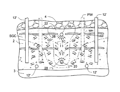
FIGS 1 and 2 are a schematic side views of the SEGD known in the prior art.
FIG. 3 is a cross-sectional view of the combined steam injection and
combustion well of the
known SEGD system.
FIG. 4 is a cross-sectional view of the combined steam injection and
combustion well of the
known SEGD taken along line 4-4 in Fig. 3.
FIG. 5 is a schematic front view of the SEOR system and method constructed in
accordance
with the principles of the present technology, with the phantom lines
depicting environmental
structure.
FIG. 6 is a schematic side view of the SEOR system and method of the present
technology.
FIG. 7 is a schematic front view of the SEOR system and method illustrating a
plurality of
vertical production wells and collapsed wormholes.
FIG. 8 is a schematic top view of the plurality of vertical and/or horizontal
production wells
utilized in the SEOR system and method.
FIG. 9 is a schematic diagram of above ground systems utilizable with the SEOR
system
and method of the present technology.
- 8 -
Date Recue/Date Received 2020-12-02
Docket No.: 205-19
FIG. 10 is a graph showing the viscosity of Lloydminster heavy oil and the CO2
saturage of
heavy oil feed #1.
The same reference numerals refer to the same parts throughout the various
figures.
DETAILED DESCRIPTION OF THE INVENTION
In FIGS. 1 and 2, the SEGD system and method is initially utilized for
producing
hydrocarbons from a formation using in situ steam generation and gravity
drainage. More
particularly, the SEGD system and method is used in removing, extracting or
producing
hydrocarbon material, such as but not limited to bitumen, from a subterranean
formation or
reservoir 2 that can include an overlying zone 4, such as but not limited to a
gas zone, water zone or
cap rock zone. The SEGD system and method includes a multi-configurable
production well 12,
amulti-configurable water injection well 18 located vertically above the
production well 12 and near
the overlying zone 4, and a multi-configurable combined steam injection and in
situ combustion
well 20 located between the production well 12 and water injection well 18.
Alternatively, the
production well 12 can also be used as a steam injection well, and the water
injection well 18 can
also be a carbon dioxide (CO2) or combustion gas production well. The
production well 12, the
water injection well 18, and the combined well 20, each can include tubing
strings, downhole
systems and assemblies, and/or any means to contribute to their intended
purpose.
It can be appreciated that the production well 12, water injection well 18 and
combined well
20 can be vertical and/or substantially vertical wells, horizontal or
substantially horizontal wells, J-
shaped wells, L-shaped wells, U-shaped wells, and/or any combination thereof.
For exemplarily
purposes regarding the present application, the production well 12, water
injection well 18 and
combined well 20 are horizontal wells approximately vertically aligned and
vertically displaced. It
can be appreciated that the known SEGD system and method locate the three
wells in vertically
displaced alignment, therefor allowing gravity to drain the mobilized oil down
to the production
well 12.
The SEGD system and method initiates a SAGD process by circulating and/or
injecting
steam into the reservoir 2 through the combined well 20 and/or the production
well 12 until a steam
chamber 22 eventually develops to the top of the reservoir 2, and a production
boundary 14 is
created adjacent the steam chamber 22, as best illustrated in FIGS. 1 and 2.
It can be appreciated
that the steam 24 can be circulated in the production well 12 alone or in
combination with the
- 9 -
Date Recue/Date Received 2020-12-02
Docket No.: 205-19
combined well 20, for a predetermined time period, for example 2-3 months.
Thus heating the
hydrocarbon material or bitumen between both the production and combined
wells.
After the predetermined time period has lapsed, any steam injection through
production well
12 is stopped, and the production well 12 is recompleted. The long string LS
of the production well
12 may be removed and a lifting mechanism (not shown), such as but not limited
to, a downhole
pump or gas lifting means, is placed downhole. Continuous steam injection can
be applied into the
surrounding reservoir 2, and thus consequently growing the steam chamber 22.
Hot hydrocarbon
fluids or bitumen emulsion 16 and steam condensate at the boundary 14 of the
steam chamber 22
flows downward and towards the recompleted production well 12. The hot
hydrocarbon fluids 16
are produced through the production well 12 and lifted to the surface via the
lifting mechanism,
while steam injection is continued through the combined well 20. This SAGD
process continues
until the steam chamber 22 reaches the top of the reservoir 2 and/or until it
reaches the overlying
zone 4, then all steam injection can be stopped.
After the SAGD process is finished, the combined well 20 can be recompleted
and
converted to an in situ SEGD combustion well 20. Water 26 is injected into the
top portion of the
reservoir 2 through water injection well 18, and allowed to fall toward the
combustion well 20 via
gravity, as best illustrated in FIG. 1.
In reference to FIG. 2, when the water front 26 approaches the combustion well
20, the
SEGD process is initiated. Combustion gases are injected into the combustion
well 20 to create an
in situ combustion 28 configured for hydrocarbon production and to vaporize
the injected water 26.
When the water 26 contacts and mixes with the in situ combusted gases 28, the
water 26 is
vaporized and converted to steam 29 which rises to the top of the reservoir 2
to create a water,
steam and CO2 envelope. The steam 29 heats and reduces the viscosity of the
surrounding
hydrocarbon material 16. After a predetermined amount of time, the treated
hydrocarbon material
16, and possible other fluids such as steam condensate, are mobilized and
drain toward the
production well 12, and are produced and lifted to the surface for further
processing.
The resulting CO2 can be sequestered into the gas or water zone 4 in the case
that the
overlying zone 4 is a gas or water zone. In the case the overlying zone 4 is a
cap rock zone, CO2
will migrate into the reservoir 2 where it can be sequestered or be produced
by adjacent wells 18.
The SEGD system and method can utilized a combined steam injection and in situ
combustion well 20, as best illustrated in FIGS. 3 and 4, includes a primary
casing 30, a slotted liner
32 including a hanger, a flexible fuel tubing 36, a flexible air, oxygen or
gas tubing 40, an igniter
- 10 -
Date Recue/Date Received 2020-12-02
Docket No.: 205-19
44, and a combustor assembly packer 34. The combustor assembly packer 34 is
configured to seal
an area of the interior of the slotted liner 32 adjacent or upstream of the
igniter 44, so that no
combustion gases escape up the slotted liner 32 and/or into the combined well
20. The gas tubing
40 can be configured to deliver oxygen, air or any gas suitable for combustion
in combination with
a fuel delivered by the fuel tubing 36.
The slotted liner 32 features a plurality of radially defined bores 33 for the
injection of steam
during the SAGD process, and for exhausting combustion gases resulting from
the in situ
combustion into the surrounding reservoir 2 during the SEGD process. It can be
appreciated that
any number and configurations of the bores 33 can be used with the slotted
liner 32. Furthermore, it
__ can be appreciated that additional peripheral systems or devices, such as
but not limited to, valves,
sleeves, jets, plugs, and degradable or erodible materials can be associated
with the bores 33.
The fuel tubing 36 features a plurality of fuel ports 38, and the gas tubing
40 features a
plurality of gas ports 42. The fuel tubing 36 and gas tubing 40 may be located
adjacent to each
other with the fuel and gas ports 38, 42 angled toward each other so that
their flows converge. It
can further be appreciated that the fuel ports 38 and gas ports 42 can be a
plurality of ports radially
defined in the fuel tubing 36 and gas tubing 40, respectively, or can be
oriented in any direction that
allows their flows to contact and mix within the slotted liner 32. It can be
appreciated that the fuel
tubing 36 and gas tubing 40 can be welded together along a longitudinal axis,
thereby creating a
paired fuel and gas tubing. Still further, it can be appreciated that the fuel
tubing 36 and gas tubing
40 may be located anywhere in the slotted liner 32 so as to allow the flows
from the fuel and gas
ports 38, 42 to contact and mix within the slotted liner 32.
The igniter 44 is located adjacent a heel of the combined well 20 and adjacent
a point of
convergence of the fuel and gas flows. The location of the igniter 44 provides
ideal ignition of the
fuel and gas flows to produce combustion or flame 46 within the slotted liner
32.
Alternate embodiment nozzles associated with the fuel tubing 36 and gas tubing
40 can be
utilized, such as but not limited to, a substantially inverted V-shaped nozzle
configuration, a
substantially inverted Y-shaped nozzle configuration or a substantially L-
shaped nozzle
configuration. It can be appreciated that the nozzles can be a single nozzle
unit associated with
each fuel port and gas port pairing, or can be designed as a manifold, which
has a single main body
featuring multiple exit ports, and/or multiple fuel and gas cylinders
extending toward their
corresponding fuel and gas ports. Optionally, the nozzle or nozzles can
include exit sleeves having
a substantially oval shape and configured to receive exit sections of the fuel
and gas cylinders
- 11 -
Date Recue/Date Received 2020-12-02
Docket No.: 205-19
therein and to combine or mix the fuel and gas flows to produce a horizontally
or substantially
horizontally extending flame.
With respect to the above described SEGD process, after the production well
12, the water
injection well 18, and the combined well 20 have been drilled or formed; the
following exemplary
SEGD process or method can be implemented.
A steam chamber 22 is created from the combined well 20 to the top of
reservoir 2.
Produced water 26 can be filtered and injected into the top portion of
reservoir 2 through the water
injection well 18 at a temperature at or lower than the steam chamber
temperature. The water 26
drains downward toward the combined well 20 by way of gravity.
Natural gas in combination with oxygen or air are injected into the combined
well 20
through fuel tubing 36 and gas tubing 40 respectively. Combustion of the
natural gas and oxygen or
air ensues downhole inside the slotted liner 32 via the igniter 44, thereby
converting the combined
well 20 into a burner.
Consequently, combustion gases 28 (steam and CO2) flow into the reservoir 2
and rise
upwardly due to the buoyancy toward the draining water 26. The draining water
26 vaporizes into
steam 29 when it contacts and mixes with the combustion gases produced by the
combined well 20.
The combined combustion gases 28 and steam 29 flow upwards and sideways toward
the
sides of the chamber 22 converting the initial steam chamber into a combined
steam and
combustion gas chamber (steam/gas chamber 22). The hydrocarbon material or
bitumen at the sides
of the chamber 22 is heated by the steam/gas chamber 22 causing the steam to
condense and some
CO2 to dissolve into the heated bitumen.
The heated bitumen including some dissolved CO2 is mobilized toward the
production well
12, and then lifted to the surface for processing. Additionally, the connate
water and the steam
condensate are drained to the production well 12 by way of gravity, and are
lifted to the surface for
processing.
The SEGD method was utilized in combination with new formation production, and
not for
rejuvenating previously processed formations that have undergone CHOP,
waterflooding, bottom
water drive, or top gas drive. While, the SEOR present technology provides
substantial benefits and
unexpected results when used for rejuvenating for example CHOP wells by
employing different
productions wells. It was not known to one skilled in the art to utilize SEGD
to recover heavy oil
from a CHOP, waterflooded, bottom water driven, or top gas driven formations.
- 12 -
Date Recue/Date Received 2020-12-02
Docket No.: 205-19
Referring now to the drawings, and particularly to FIGS. 5-9, embodiments of
the SEOR
system and method of the present technology is shown and will be described. In
the exemplary, the
SEOR system and method of the present technology can be utilized in a
formation that has
previously gone through a heavy oil extraction process, such as but not
limited to, CHOP,
waterflooding, bottom water drive, or top gas drive.
In the exemplary, as illustrated in FIGS. 5 and 6, previously used vertical or
horizontal wells
PW in the CHOP process create and leave behind wormholes or conduit network WH
as a result of
the sand production creates. Gas saturation increases to replace the produced
oil, connate water and
sand. Eventually, the reservoir pressure declines to a low pressure such that
the wells are no longer
productive.
The present technology can take advantage of these wormholes by collapsing
them to create
permeable channels to more efficiently mobiles heavy oil toward production
wells. The present
technology can also be utilized in reservoirs having a payzone thickness or
depth not suitable for
SEGD or SAGD operations. This is in part because the present technology
utilizes a mobile
pressure front created by in situ combustion resulting in the in situ creation
of steam and CO2
without the need of a drainage production well that requires the reservoir
payzone to have a
substantial thickness or depth.
The SEOR system and method of the present technology can be utilized to
rejuvenate and/or
repressurize a non-productive or a limited-productive reservoir 2 resulting
from a previously
extraction process, such as but not limited to CHOP, waterflooding, bottom
water drive, or top gas
drive. The reservoir 2 may be below an overlying zone 4, such as but not
limited to a gas zone,
water zone or cap rock zone, and may be above an underlying zone 3.
Furthermore, the reservoir 2
may be a single or a series of thin oil payzones. Still further, the reservoir
2 may be a new
formation that has not undergone any previous extraction process.
In view of the foregoing non-thermal production methods and the current states
of the
reservoirs, the present technology provides an enhanced oil recovery method
and process that can
profitably increase the production and reserves from these reservoirs. This
invention mobilizes
heavy oil using various mechanisms such as collapsing the wormholes CWH,
repressurizing the
reservoirs with carbon dioxide gas saturation, dissolving CO2 into the oil and
swelling it, reducing
the viscosity of the oil thermally and with CO2, and further displacing oil
with CO2 and steam or hot
water. The SEOR method can utilize the water injection well 18 and the
combustion well 20 of the
SEGD system, but replaces the vertically aligned and displaced production well
of SEGD with a
- 13 -
Date Recue/Date Received 2020-12-02
Docket No.: 205-19
plurality of vertical production wells 12' that are located around the
injection and combustion wells
18, 20, as best illustrated in FIG. 8. It can be appreciated the production
wells 12' can be horizontal
wells located laterally offset from the combustion well 20. As discussed
above, the combustion
well 20 can be a combined well configured as a production or combustion well.
If the overlying zone 4 is a cap rock, then the CO2 may be retained thereunder
to maintain or
increase pressure within the reservoir 2 or for production from an additional
production well located
in an area between the reservoir 2 and overlying zone 4. In an alternative, if
the overlying zone 4 is
for example sand, the CO2 may flow therein for sequestration.
To attain this, the present technology can include injecting water 26 into
reservoir 2 from the
top horizontal well 18. The water 26 drains down toward the combustion well 20
to create a liquid
water inner core WC. A hydrocarbon fuel is mixed with oxygen or air and
combusted inside a liner
32 of the bottom horizontal well 20. The hydrocarbon fuel can be, but is not
limited to, natural gas,
fuel oil, heavy oil, bitumen, residuum, emulsified fuel, multiphase superfine
atomized residue,
asphaltenes, petcoke, coal and combinations thereof. The resulting combustion
gases 28 contact the
flowing water 26 to create a steam and combustion gases 28 that penetrate,
permeate and travel into
the reservoir 2. The combustion gases 28 vaporizes most of the injected water
26 to steam by heat
transfer mechanisms of conduction, convection and fluid mixing to create a
steam and CO2 gas
chamber SGC. The combined steam and CO2 SC flows laterally away from injection
well 18 and
combustion well 20. The steam will heat the adjacent formation 2 and oil, and
will condense to hot
water HW. The CO2 CO will permeate ahead pressurizing the reservoir 2 and
dissolve into the oil,
swelling it and reducing its viscosity thereby allowing the oil to flow OF by
the moving CO2 CO
pressure front toward the production wells 12'. The CO2 will contact the
reservoir oil through
existing wormholes WH and through the continuous gas saturation or phase. Some
of the
wormholes WH will collapse CWH due to oil viscosity being reduced
significantly by CO2, as best
illustrated in FIG. 7. Consequently, the wormholes can be collapsed by the
introduction of the
resultant CO2, the resultant steam and/or by a rapid depressurization at the
production wells.
It can be appreciated that the water inner core WC can develop into a pyramid-
like
configuration first and then to an oval configuration until it contacts the
combustion front from the
combustion well 20. Surrounding the water inner core WC can be a steam,
combustion gas and
water chamber SGWC mixture. This mixture chamber SGWC can propagate and
permeate
vertically and laterally from the combustion well 20 and into the surrounding
formation, thereby
mobilizing the heavy oil. It can further be appreciated that the mixture
chamber SGWC may
- 14 -
Date Recue/Date Received 2020-12-02
Docket No.: 205-19
angularly expand from the combustion well 20 and then taper off into a more
substantial horizontal
flow. This can create a thickness or depth of the mixture chamber SGWC being
greatest adjacent
or near the combustion well 20, and decreasing the farther laterally away from
the combustion well.
This mixture chamber SGWC front can move laterally depending on the formation
characteristics, distance between the injection well 18 and combustion well
20, the amount of water
injected from the injection well 18, the type and amount of fuel and/or air
and/or oxygen injected
into the combustion well 20, the length of time of injection of water, fuel
and/or air or oxygen, the
starting and/or length of time of production utilizing the production wells
12', PW, and the number
and/or location of the production wells 12', PW.
Still further, the control of production can be used to regulate the pressure
created by the in
situ combustion. Even further, additional CO2 can be injected into the
reservoir 2 to assist in
repressurizing or increase the pressure. This additional CO2 can be injected
utilizing a separate
injection well (not shown) or the water injection well 18, and the additional
CO2 can be supplied
from a previous CO2 recovery process.
After the reservoir pressure have increased significantly and close to the
original reservoir
pressure, further collapsing of the wormholes CWH can occur by suddenly
reducing the pressures
at nearby production wells 12'. It can be appreciated that the production
wells 12' can be located
through or near the wormholes WH. If needed the production wells 12' can be
temporarily
equipped with sand screens to prevent sand production. The collapsed wormholes
CWH remain as
useful high permeability conduits in the reservoir 2.
After the wormholes CWH are collapsed, the production wells 12' can be further
put on
production to produce the mobilized oil OF, the hot water HW, the CO2 gas CO
and any other
usable resource. Referring to FIG. 9, at the surface the wells 12', 18, 20 may
be associated with
wellhead equipment 50. The produced oil can be separated utilizing know
separation techniques
and systems 52 and the transferred 54 to be stored, further processes and/or
sold. The produced hot
water from the separator 52 can be filtered or processed 56 and/or stored 60,
and reinjected into top
water injection wells 18. It can be appreciated that new water can be used
from other sources 62.
Combustible gases, such as natural gas, or liquids can be separated from the
produced
material utilizing separator 52 and recirculated 58 to fuel storage 66 for
injection into the
combustion well 20. New fuel or hydrocarbon fuel 66 and oxygen or air 64 can
be continued to be
combusted in the combustion wells 20 to vaporize the injected water to steam.
- 15 -
Date Recue/Date Received 2020-12-02
Docket No.: 205-19
Any produced CO2 can be separated 52 and used for CO2 flooding or water and
CO2 gas
(WAG) flooding of nearby heavy oil wells. Alternatively, any produced CO2 can
be injected back
into the reservoir 2 to further increase the pressure or for sequestration.
In use, it can now be understood that after CHOP or Cold Heavy Oil Production
has
occurred using horizontal wells, the SEOR method of the present technology can
be utilized to
rejuvenate and repressurize a fully or partially depleted CHOP well, to
produce and recover further
heavy oil from the formation.
After CHOP, two to three SEGD horizontal wells can be drilled in selected
locations
between or adjacent the existing wells PW utilized in the CHOP process. If
needed and optional,
water can be injected into the upper well 18 and oil can be produced from the
lower combustion
well 20, or water can be injected into the lower combustion well 20 and oil
produced from the upper
well 18. The upper well 18 may be recompleted to a water injection well, and
the lower production
well can be recompleted to a combustion well 20.
If needed, water may be blown out of the lower well 20 prior to recompleting
to the
combustion well or prior to combustion.
Water 26 is injected into the upper zone of the formation 2 utilizing the
upper horizontal
injection well 18. Natural gas and oxygen is injected and combusted in the
combustion well 20 to
create combustion gas 28 that moves outwardly therefrom. The water 26 gravity
drains toward the
combustion well 20 to contact, mix and heat transfer with the combustion gas
28 vaporizing the
water to steam SC.
The steam SC heats the oil OF and condenses to water HW. Steam SC, hot water
HW and
CO2 CO gases migrate outwards in the reservoir 2, increasing reservoir
pressure, and pushing and
displacing reservoir oil and natural gas towards the nearby production wells
12'. The combustion
CO2 migrates more into the reservoir 2 through the wormholes WH and gas phase,
cools, becomes
a solvent into the oil, and repressurizes the reservoir.
The heated heavy oil or bitumen including some dissolved CO2, the connate
water and the
steam condensate are mobilized toward the production wells 12', and then
lifted to the surface for
processing.
In the case where the reservoir 2 is entirely a bitumen reservoir; the CO2 can
be produced
from the top of the reservoir to maintain a predetermined and/or approved safe
steam chamber
pressure. The produced CO2 can be conditioned for sequestration, possibly
dehydration and
liquefaction.
- 16 -
Date Recue/Date Received 2020-12-02
Docket No.: 205-19
The required energy (net) is estimated as the sum of the vaporization energy
of the injected
water 26, plus any water from zone 4.
During and after the SEOR process, produced fluids from the production wells
12' are lifted
to the surface are then pipelined to a processing plant. The produced fluid
can be degassed and the
produced liquid is transferred to the free water knock out. The produced free
water can be
separated out in the free water knock out and is transferred to the produced
water tank or vessel.
A treater breaks the produced emulsion to produce pipeline specification
bitumen that can be
blended with diluent. The separated, produced water can be transferred from
the treater to the
produced water tank or vessel. Produced water can then be transferred from the
produced water
tank or vessel to the water injection wells 18 at the well pads. If needed,
the produced water can be
filtered at the exit discharge from the produced water tank or vessel and
preheated using heat
exchangers with hot produced fluids.
Natural gas and oxygen or air can be pipelined in separate pipelines to the
well pads and
then to the combined well 20. If oxygen is used, an oxygen plant that produces
oxygen from the
atmosphere can be used. If CO2 gas is removed or produced from the steam
chamber via the water
injection well 18, then the produced CO2 gas can be dehydrated and liquefied
for sequestration into
an abandoned SAGD or SEGD chamber, or into an aquifer.
When the reservoir 2 has been re-pressured and mixing of CO2 solvent and oil
has occurred,
produce some or all of the surrounding wells PW and/or drill and produce new
vertical or
horizontal production wells 12'. Production of the surrounding wells could be
continuous or cyclic
if needed.
It can be appreciated that if a horizontal production SEGD well is located
vertically below
and vertically aligned with the combustion well 20 as per SEGD, this SEGD
production well may
become unproductive, be shut in or may be converted to a secondary combustion
well.
In the exemplary, most of Saskatchewan and Alberta heavy oil is extracted
using the
CHOP process or foamy oil production using horizontal wells¨ pressure
depletion, foamy oil
without or with sand production and wormholes. Overall recovery factor is very
low - <7% initial
oil in place (I0IP) primary and ¨2% IOIP more for current enhanced recovery
for Saskatchewan,
11.1% for Alberta.
There are many advantages of the SEOR process of the present technology over
the known
SEGD and/or SAGD processes. The SEOR process of the present technology has
higher energy
efficiency by way of direct combustion and heating of the steam chamber, with
no heat losses and
- 17 -
Date Recue/Date Received 2020-12-02
Docket No.: 205-19
steam losses in flue gases and in all surface equipment. The emissions are
reduced with CO2 gas
sequestration, and no combustion emissions of CO2, CO, NOx and/or SOx.
The SEOR process of the present technology has less to no make-up water as
compared to
SAGD or steam injection, and has negligible to no disposed water. Water
treatment is less complex
and cost effective, and may require only filtration. For steam generation, the
SEOR process may
use surface boilers or once through steam generators but only for a short
initial period to create a
small steam chamber to the top of the reservoir.
The known SEGD process was previously not advantageous or contemplated for
utilization
with post CHOP wells or thin oil payzones that require significant height for
proper gravity
drainage. The present technology utilizes at least in part some of the SEGD
system and method to
extract a significant amount of the billions of barrels of unrecoverable oil
from thin oil payzones or
partially depleted formations.
Some potential benefits and unexpected results of utilizing the SEOR system
and method
are:
The utilization of a combined SEOR and SEGD process.
Utilizing steam, CO2 and/or hot water to push oil laterally toward nearby
vertical and/or
horizontal productions wells.
CO2 re-pressurization of the reservoir.
CO2 solubility into and viscosity reduction of the oil.
Collapsing of wormholes created during previous oil extraction processes by
viscosity
reduction of the oil by CO2 and heat, and further collapsing by rapid
depressurization.
Collapsed wormholes are permeable allowing oil to flow toward the production
wells.
Enhanced foamy oil production from existing wells.
CO2/WAG EOR in the waterflood reservoirs.
CO2 capture and sequestration in the reservoirs.
Further in the exemplary, the amount of unrecovered oil left behind by heavy
oil extraction
is significant, as shown in Table 1 illustrating heavy oil data of
Saskatchewan and Alberta heavy oil
fields.
Area Initial Oil in Recoverable Re coverabl
Unrecoverable Unrecoverable
Place (I0IP) Oil, e Oil, Oil, Oil,
billion barrels billion barrels %IOIP billion barrels %IOIP
Lloydminster -1H 20.70 1.83 8.8 18.9
91.2
Kindersley - 2H 5.35 0.55 10.3 4.8
89.7
- 18 -
Date Recue/Date Received 2020-12-02
Docket No.: 205-19
Sask Heavy 26.05 2.38 9.1 23.7
90.9
Alta Heavy
12.15 1.35 11.1 10.8 88.9
Primary
Table 1 - Saskatchewan Heavy Oil Data
As appreciated by Table 1, there are billions of barrels of oil that were
previously thought as
unrecoverable. The SEOR process is unique in that it overcomes the
disadvantages of known
SEGD and/or SAGD processes to extract previously thought unrecoverable heavy
oil from thin
payzones or from depressurized wells due from previous extract processes.
It is known that steam and CO2 injection can result in a dramatic improvement
in the rate of
final oil recovery as compared to steam only injection. The addition CO2 to
steam injection results
in lowering the partial pressure of steam and reducing steam temperature,
which can have an
adverse effect on viscous oil recovery. On the other hand, CO2 solubility in
the oil increases at the
lower temperatures and higher pressures, which can be beneficial in reducing
oil viscosity and
increasing oil swelling. However, separately injecting steam and CO2 requires
additional wells to
be drilled and/or more complicated machinery at the surface. This results in
higher costs and longer
setup times.
Taking for example the Lloydminster area, which is located in east-central
Alberta and west-
central Saskatchewan, contains a large amount of heavy oil resources in a
series of thin oil belts
with less than 10m payzones. Such a thin payzone makes the use of SAGD and
cyclic steam
stimulation processes undesirable, uneconomical and in some cases not
applicable. This in part due
to the excessive heat losses and limited drainage height. An alternative
option in such formations is
to use solvent injection, such as CO2, to dilute and/or swell the heavy oil.
The utilization of CO2 to decrease the viscosity of heavy oil and its
advantages is known, as
described by Xiaoli Li, Daoyong Tony Yang and Zhaoqi Fan (University of
Regina) in a published
article entitled Phase Behaviour and Viscosity Reduction of CO2-Heavy Oil
Systems at High
Pressures and Elevated Temperatures (Document ID: SPE-170057-MS; Publisher:
Society of
Petroleum Engineers; Source: SPE Heavy Oil Conference-Canada, 10-12 June,
Calgary, Alberta,
Canada; Publication: Date2014). The advantage of CO2 was quantified utilizing
the two-parameter
double-logarithm relation (see Equation 1) to accurately reproduce the
measured viscosity of the
Lloydminster heavy oil at the atmospheric pressure and various temperatures.
- 19 -
Date Recue/Date Received 2020-12-02
Docket No.: 205-19
tog ic, pogiG GO] = ¨3.7042 tog 10(T) + 9.7600
(1)
where p is viscosity of the heavy oil in cP and T is temperature in K. The
viscosity of
Lloydminster heavy oil at ambient temperature (i.e., 298.15 K) and pressure
(i.e., 101.325 kPa) is
calculated to be 8477.1 cP.
It is apparent that a key recovery mechanism of CO2 is viscosity reduction.
This is evident
by the graph as shown in FIG. 10 provided in the above-identified publication
to Li et al. that
illustrates the viscosity of Lloydminster heavy oil and the CO2 saturage of
heavy oil feed #1.
Consequently, the use of CO2 saturation substantially reduces the viscosity of
heavy oil
thereby supporting the advantages of the SEOR method of the present
technology. However and in
contrast with known methods, the SEOR method avoids the disadvantage of
generating steam and
injecting CO2 from the surface by creating the steam and CO2 in situ with
minimal resources since
the injected water can be water produced from previous processes, and
combustion is created in situ
utilizing recoverably natural gas and oxygen or air.
Previous solutions have been known to force a tight packing of reservoir sand
in an annulus
around the well by collapsing the reservoir sand into that open space. This
was previously
accomplished by depressuring the wellbore as rapidly as possible by displacing
out any fluids in the
wellbore with nitrogen, then opening the well to atmosphere at the surface.
This process is again
costly and time consuming in light of the present SEOR method.
The SEOR method automatically collapses the wormholes as a result of the CO2
saturation,
with the CO2 being a product of the in situ combustion. No additional gas
injection, such as
nitrogen, is required.
While embodiments of the sustainable enhanced oil recovery of heavy oil has
been
described in detail, it should be apparent that modifications and variations
thereto are possible, all of
which fall within the true spirit and scope of the invention. With respect to
the above description
then, it is to be realized that the optimum dimensional relationships for the
parts of the invention, to
include variations in size, materials, shape, form, function and manner of
operation, assembly and
use, are deemed readily apparent and obvious to one skilled in the art, and
all equivalent
relationships to those illustrated in the drawings and described in the
specification are intended to be
encompassed by the present technology. And although producing hydrocarbons
from a heavy oil
formation or reservoir using in situ steam and carbon dioxide generation have
been described, it
should be appreciated that the sustainable enhanced oil recovery of heavy oil
herein described is
- 20 -
Date Recue/Date Received 2020-12-02
Docket No.: 205-19
also suitable for producing oil from new formations and or formations that
have previously been
processed using other methods from those described herewith in the exemplary.
Therefore, the foregoing is considered as illustrative only of the principles
of the invention.
Further, since numerous modifications and changes will readily occur to those
skilled in the art, it is
not desired to limit the invention to the exact construction and operation
shown and described, and
accordingly, all suitable modifications and equivalents may be resorted to,
falling within the scope
of the invention.
- 21 -
Date Recue/Date Received 2020-12-02