Note: Descriptions are shown in the official language in which they were submitted.
85344388
FASTENING DEVICES FOR EXPLOSION-PROOF ENCLOSURES
This application is a divisional of Canadian Patent Application Number
2,871,884 filed on March 13, 2013.
CROSS-REFERENCE TO RELATED APPLICATIONS
[0001] This application claims priority to United States Provisional
Patent Application
Serial Number 61/640,827, titled "Fastening Devices for Explosion-Proof
Enclosures" and
filed on May 1,2012.
[0002] The present application is further related to United States Patent
Application
Serial Number 13/793,672, titled "Fastening Devices for Explosion-Proof
Enclosures."
[0003] The present application is further related to United States Patent
Application
Serial Number 13/794,402, titled "Fastening Devices for Explosion-Proof
Enclosures."
[0004] The present application is further related to United States Patent
Application
Serial Number 13/794,433, titled "Cover Release Mechanisms for Enclosures."
[0005] The present application is further related to World Intellectual
Property
Organization (WIPO) Patent Application Serial Number W02011/084152, titled
"Enclosure
Clamps and Clamp Systems," filed on January 5, 2010.
TECHNICAL FIELD
[0006] The present disclosure relates generally to explosion-proof
enclosures and/or
flame-proof, and more particularly to systems, methods, and devices for
securing a cover of
an explosion-proof enclosure to a body of the explosion-proof enclosure.
BACKGROUND
[0007] Explosion-proof receptacle housings and enclosure systems are used
in
many different industrial applications. Such explosion-proof receptacle
housing and
- 1 -
CA 3060768 2019-10-30
WO 2013/165561 PCT/US2013/030214
enclosure systems may he used, fOr example, in military applications onboard
.ships,
assembly plants, power plants, oil refineries, petteehemical plants, and other
harsh
enviromnents. At times, the equipment located inside sucit explosion-proof
receptacle
housing. -and enclosure =Systems is used to control motors and other
industrial
equipment,.
[09081 In order for an xplosion-proof enclosure to inc.,,et
certain standards and
requirements, the wirer of the enclosure must be sealed to the body of the
enclosure
within certain tolerances. Often, this requires a large nuniber (30 or more)
of bolts to
be tightened_ Consequently, securing all of the bolts at the appropriate
torque is a
. very time-consuming Pros. In addition, removing all of the bolts to access
one or
more components inside the explosion-proof enclosure is a time-consuming
process.
SUMMARY
100091 In ueneral, in one aspect, the discloSure relates to a
syStent fin-
faStening a cover to a body of an explosion-proof enclosure using- a number of
=
fastening .devices. Each fastening device can include a fastener that includes
a stem
having quick release threads, where the 'stern traverses a first aperture in a
=flange and
= a second aperture. in an opposing flange. The fastener of each. fastening
device can
also include a head rotatably coupled to the stem, where the head has mating
threads
. .
for the quick release threads of the stem, and Where the head. abuts against
the
opposing flange.
[0010] In another aspect, the disclosure can generally relate to a
system for
fastening a cover to a body of an explosion-proof enclosure. The system can
include
a flange having a number of first Apertures traverSitig. therethroughõ The
system can.
also include an opposing flange that abuts the flange; where the opposing
flange has a
number of second apertures traversing therethrough. The system Can farther
include a
number of fastening devices, Each fastening device can include A fastener
receiver
disposed on the opposing flange, where the fastener receiver has, mating
threads.
.Each fastening device can also include a fastener having, a proximal. end and
a distal
end, where the proximal end abuts the flange, where the fastener traverses a
first
aperture and a second aperture, where the distal end \ comprises quick release
threads
disposed thereon, and where the quick release threads are threadably coupled,
to the
mating threads of the fastener receiver =
=
CA 3060768 2019-10-30 =
WO 2013/165561
PCT/US2013/030214
[0011.] In yet another aspect, the disclosure can generally relate to
a system for
fastening a cover to a body of an explosion-proof enclOsure. The system can
include
a flange having a plurality of slotted apertures traversing therethrough. The
system
can also include an opposing flange that abuts the flange, where the opposing
flange
has an anchor receiver. The system can further include a number of fastening
devices.
Each fastening device can include a stem that Moves within a slotted aperture
of the
Slotted apertures, where the stem has a bolt length greater than a flange
height. Each
fastening device can also include a head mechanically coupled to a distal end
of the
stem and that abuts against an miter 'surface of the flange; Each fastening
device can
further include an anchor movably coupled within the anchor receiver of the
opposing
flange and mechanically coupled to a proximal end of the stem.
[00121 In still another aspect, the disclosure can generally relate
to a system
for fastening a cover. to a body of an explosion-proof enclosure. The system
can
include a flange, and an opposing flange that abuts the flange. The system can
also
include a first load distributing member disposed on the flange, where the
first load
distributing member has a number'of slotted apertures traversing therethrouuh.
The
system can further include a second load distributing member disposed on the
opposing flange, where the second load has an anchor receiver. The system can
also
include a number of fastening devices. Each fastening device can include a
stem that
moves within a slotted aperture of the plurality of slotted apertures, where
the stem
has a boll length greater than a flange height, an opposing fiance height, and
a first
load distributing member height. Each fastening device can also include a head
mechanically coupled to a distal end of the stein and that abuts against an
outer
surface of the flange. Each fastening device can further include an anchor
disposed
within and movably coupled to the anchor receiver of the second load
distributing
member, where the anchor is also mechanically coupled to a proximal end of the
stem.
[pm] In yet another aspect, the disclosure can generally relate to
a system for
fastening a cover to a body of an explosion-proof enclosure using a number of
fastening devices, :Each fastening device can include a cam fixture having a
cam slot,
a first aperture, and a cam feature, where the cam fixture is disposed on a
flange of the
explosion-proof enclosure. Each fastening device can also include a .fastener
movably
coupled to the cam fixture within the first aperture, where the fastener has a
stem, a
head, and a base, where the head is mechanically ceupled to one end of the
stem,
- 3 -
CA 3060768 2019-10-30
85344388
where the base is mechanically coupled to an opposite end of the stem, and
where the base fits
within the cam slot and rotatably couples to the cam fixture. The stem can
traverse a second
aperture in an opposing flange of the explosion-proof enclosure. The head can
abut against the
opposing flange.
[0013a] According to one aspect of the present invention, there is
provided a system for
fastening a cover to a body of an enclosure, comprising: a flange comprising a
plurality of
first apertures traversing therethrough; an opposing flange that abuts the
flange, wherein the
opposing flange comprises a plurality of cavities traversing therethrough; and
a plurality of
fastening devices, wherein each fastening device of the plurality of fastening
devices
comprises: a fastener receiver disposed in a cavity of the plurality of
cavities disposed in the
opposing flange, wherein the fastener receiver comprises a second aperture
that traverses a
height of the fastener receiver, and wherein the fastener receiver further
comprises a cam
feature disposed on the fastener receiver; and a fastener comprising a head, a
base, and a stem,
wherein the head is mechanically coupled to a first end of the stem, wherein
the base is
mechanically coupled to a second end of the stem, wherein the head abuts
against the flange,
wherein the stem traverses a first aperture of the plurality of first
apertures and the second
aperture of the fastener receiver, and wherein the base abuts against an outer
surface of the
cam feature of the fastener receiver.
[0013b] According to another aspect of the present invention, there is
provided a
system for fastening a cover to a body of an enclosure, comprising: a flange
comprising a
plurality of first apertures traversing therethrough; an opposing flange that
abuts the flange,
wherein the opposing flange comprises a plurality of second apertures
traversing therethrough
and a plurality of cam features; and a plurality of fastening devices, wherein
each fastening
device of the plurality of fastening devices comprises: a stem; a head,
wherein the head is
mechanically coupled to a first end of the stem; and a base, wherein the base
is mechanically
coupled to a second end of the stem, wherein the head abuts against the
flange, wherein the
stem traverses a first aperture of the plurality of first apertures and a
second aperture of the
plurality of second apertures, and wherein the base abuts against an end of a
cam feature of
the plurality of cam features.
- 4 -
CA 3060768 2019-10-30
85344388
[0013c] According to still another aspect of the present invention, there
is provided a
fastening device comprising: a stem; a head, wherein the head is mechanically
coupled to a
first end of the stem; and a base, wherein the base is mechanically coupled to
a second end of
the stem, wherein the head is configured to abut against a flange of an
enclosure, wherein the
stem is configured to traverse a first aperture of a plurality of first
apertures disposed in the
flange, wherein the stem is further configured to traverse a cavity of a
plurality of cavities
disposed in an opposing flange of the enclosure, and wherein the base is
configured to abut
against an outer surface of a cam feature of a plurality of cam features.
[0014]
BRIEF DESCRIPTION OF THE DRAWINGS
[0015] The drawings illustrate only example embodiments of fastening devices
for explosion-
proof enclosures and are therefore not to be considered limiting of its scope,
as fastening
devices for explosion-proof enclosures may admit to other equally effective
embodiments.
The elements and features shown in the drawings are not necessarily to scale,
emphasis
instead being placed upon clearly illustrating the principles of the example
embodiments.
Additionally, certain dimensions or positionings may be exaggerated to help
visually convey
such principles. In the drawings, reference numerals designate like or
corresponding, but not
necessarily identical, elements.
[0016] Figures lA and 1B show various views of example fastening devices
in
accordance with certain example embodiments.
[0017] Figures 2A-2C show various views of alternative example fastening
devices in
accordance with certain example embodiments.
[0018] Figure 3 shows another alternative example fastening device in
accordance
with certain example embodiments.
- 4a -
Date Recue/Date Received 2021-04-22
85344388
DETAILED DESCRIPTION OF EXAMPLE EMBODIMENTS
[0019]
The example embodiments discussed herein are directed to systems,
apparatuses, and methods of fastening a cover of an explosion-proof enclosure
to a body of
the explosion-proof enclosure. While the example embodiments discussed herein
are with
reference to explosion-proof enclosures, other types of non-explosion-proof
enclosures (e.g. ,
junction boxes, control panels, lighting panels, motor control centers,
switchgear cabinets,
relay cabinets) or any other type of enclosure (e.g., a flame-proof enclosure)
may be used in
conjunction with example embodiments of fastening devices.
- 4b -
CA 3060768 2019-10-30
85344388
[00201 in one or
more example embodiments, an explosion-proof enclosure
(also known as a flame-proof enclosure) is an enclosure that is configured to
contain
an explosion, that originates inside the enclosure, Further, the explosion-
proof
enclosure is configured to allow gases from inside the enclosure to escape
across
joints of the enclosure and cool as the gases exit the explosion-prOof
enclosure.. The
joints are also known as flame paths and exist where two surfaces meet and
provide a
path, from inside the explosion-proof enclosure to outside the explosion-proof
enclosure, along which one or more gases may travel. A joint may be a Mating
of any
two or more Surfaces. Each surf= may be any type of surfacte, including but
not
limited to a flat surface, a threaded surface, and a serrated surface,
[40211 In one or more example embodiments, an explosion-proof is
subject to meeting certain standards and/or requirements, For example', NEMA
sets
standards with which an enclosure must comply in order to quality as an
explosion-
proof enclosure. Specifically, NEMA Type 7, Type 8, Type 9, and Type 10
enclosures set standards with which an explosion-proof enclosure within a
hazardous
location must comply. For example, a NEMA Type 7 standard applies to
enclosures
constructed for indoor Use in certain hazardous locations. Hazardous
'locations may
be defined by one or more of a number of authorities, including but not
limited 'to the
National Electric Code (e.gõ Class 1, Division I) and Underwriters'
Laboratories, Inc.
(UL) [IL
1203). For example, a Class 1 hazardous area under the National
Electric Code is an area in Which flammable gases or vapors may be present in
the air
in sufficient quantities to be explosive.
100221 As a
Specific example, NEMA standards for an explosion-proof
'enclosure of a certain size orrange of sizes may õrequire that in a Group B,
Division
area, any flame path of an explosion-proof enclosure must he at least 1 inch
long
(contintouS and Without interruption), and the gap between the surfaces cannot
exceed 0,0015 inches. Standards created and maintained by NEMA. may be found
at
www.nema.org/stds.
100231 Some
standards also require that one or more tools are used to open an
explosion-proof enclosure. Example embodiments described herein require the
use of
a tool, whether custom made or standard, to disengage the fastening device and
opeii
the explosion-proof enclosure. Each of the components of the example.
fastening.
devices (e.g., fastener, fastener receiver, load distributing member, handle,
cam, pin)
- -
Date Recue/Date Received 2021-04-22
WO 2013/165561 PCT/US2013/030214
can be made from one or more of a number of suitable Materials, including but.
not
limited to stainless Steel, plastic, aluminum, etlaliliQ, rubber, and. iron.
100241 Example embodiments of fastening devices for explosion-proof
enclosures will be described more fully hereinafter with reference 10 the
accompanying drawings, in which example embodiMents. of 111st-ening. devices
for
explosion-proof enclosures are shown. Fastening devices for explosion-proof
enclosures may, 'however, be embodied in many different forms and should not
be
construed as lithited to the example embodiments sot forth. herein. Rather,
these
example embodiments are provided so that this disclosure will be thorough ,and
complete, and will fully convey the scope of fastening devices for explosion-
proof
enclosures, to those or ordinary skill .in the art: Like, but not necessarily
the same,
elements (also sometimes called components) in the various figures are denoted
by
like reference numerals for consistency.
[0025] Figures IA and IR show various views of an enclosure system
100 that
uses an example fastening device 110 in accordance with one or more e.x.ample.
embodiments: Specifically. Figure lA shows a front view of the enclosure
system
'100, Figure I B shows a crosasectional top view of the example fastening
device 11Ø
In one or more embodiments, one or more of the features shown in Figures lA
and 1.B
may be omitted, repeated, and/or substituted. Accordingly., embodiments of
fastening
devices for explosion-proof enclosures should not be considered limited to the
specific arrangements of components shown in Figures lA and 113.
[00261 = Referring to Figures IA and 1B, the enclosure system 100 of
Figure
IA includes an. explosion-proof enclosure 103 using at least One example
fastening
device 110 in accordance with certain example. embodiments. The explosion-
proof
enclosure -103 includes an enclosure Cover and a cover flange 122 around the
perimeter of the enclosure cOvet. The cover flange 122 is Mated to (abuts
against) a
body flange 132 that is positioned around the perimeter of the enclosure body.
The
cover flange 122 and the body flange 1.32 each have a*height or thiekness,
which may
be the same or different from each other. in .certain, embodiments, one or
more hinges
may be positioned along one side of the enclosure cover and, a corresponding
side of =
the .enclosure body. When most, if not all, of the. example fastening devices
110 are
removed, the enclosure cover can be separated from the enclosure. body
100271 As shown in Figure IA, the example -fastenings device 110
is, arranged
around the perimeter of the cover flange 122 and the body flange 132. The air
gap
- 6 -
=
CA 3060768 2019-10-30
WO 2013/165561
PCT/US2013/030214
that forms between the surfaces of the cover flange 122 and the body flange
132 when
the cover .flange 122 and the body .flange 132 Converge is the flame path 169.
One of
the functions of the fastening device 110 is to ensure that the flame path
1.69 is within
an accepted tolerance in light of a particular standard for the explosion-
proof
enclosure .103,
100281 As shown in Figures IA and 1B, the fastening device
110 uses a quick
release fastener 109, which includes a head 115 and a threaded stem 1.18. The
head
115 can be shaped and/or configured -to accommodate one Or more of a number of
tools. For example, the head 115, when looking from above, may be shaped like
a
hexagon. AS another example, the head 115 may have a slot that traverses the
top
surface.
[00291 The threads 125 oii the threaded stem 118 May be
disposed along all or
a portion of the surface of the threaded .stein 118, In certain example
embodiments,
the threads 125 on the threaded Stem 118 have a substantial thread profile. In
other
Words, the shape and/or pitch of the threads 125 are extreme so that the quick
release
fastener 109 can be secured to a fastener receiver 120 by rotating the. quick
release
fastener 109 approximately 900. Such rotation can be Clockwise or
counterclockwise,
depending on whether the threads .125 are left-handed or right handed.
[00M] The term "quick release" is meant to generally
define fasteners that can
take less than one full turn of travel to reach optimal tension. Such threads
on a quick
release fastener can be called quick release. threads. For example, the quick.
release
fastener can travel 90 to reach the end of the mating thread to which the
quick release
threads of the quick release fastener are Threadably coupled. Alternatively,
the quick
= release fastener can travel any other distance, including but not limited
to
approximately 45', 180', and 270". In certain example embodiments, the quick
release fastener can travel more than one turn (greater than 360').
10031] In addition, or in the alternative, the threads 125
on the threaded stem
118 can be interrupted, In other words, each of the threads 125 on the
threaded stem
118 may not continue around the entire perimeter of the. threaded stem 118.
The
.threads 125 on the threaded stem 118 can also, or in the alternative, have,
multiple
lead threads (e4;.: triple lead threads, quad lead threads). In certain
example,.
embodiments, the quick release fastener 109 is secured to the fastener
receiver 120 by
rotating the quick release fastener 109 less than 90". For example, the quick
release:
CA 3060768 2019-10-30
WO 2013/165561 =
PCT/US2013/030214
=
fastener 109 can be secured to the fastener receiver 120 by rotating the quick
release.
fastener 109 approximately 45 .
100321 The fastener receiver .120 can be secured to the body
flange 132 or the
cover flange 122. using an aperture in the body flange 132 or the cover flange
122,
Where the aperture is Shaped to fit the fastener receiver 120 without allowing
the
fastener receiver 120 to move transversely as'the quick release fastener 109
is coupled
to the fastener receiver .120. In certain example embodiments, the fastener
receiver
120 is integrated with the body flange 132 and/or the cover flange 122, Where
the
mating threads 1.26 are machined itito the body. flange 1.32 and/or the cover
flange
yr. =
100331 If the fastener receiver 120 is a separate component
.frorn the body
flange .132 and/or the cover flange 122 (i.e., if the fastener receiver 1.20.
is not
integrated with the body flange 1:32 and/or the cover flange 122), the
fastener receiver
120 can have a shape that corresponds to a shape of the body flange 132 and/or
the
cover flange 122 into which the fastener receiver 120 is disposed. Examples of
such
shapes can include, but are not limited to, a triangle, a. square, and a
hexagon. Such a
shape can be symmetrical, asymmetrical, or random.
[0034] In certain example embodiments, the mating threads- 126
of the
listener roOver. 120 can mate with the *threads 125 of the threaded stem 118.
In
addition, the fastener receiver 120 can have one or more additional features.
For
example, as shown in Figure 113, the fastener receiver 120 can have one or
more of
number of stops 124 that prevent the threaded stem 118 from turning beyond a
certain
= angle (e.g., 90 , 45'). In this case, as shown in Figure 113., each stop
124 can impede
the rotational path of a thread 1.25 (specifically, the distal portion of the
thread 125) of
the threaded stem 118. As another example, the fastener receiver 120 can have
one or
more of a number of passages 140 that provide clearance for insertion and/or
extraction of the threaded Stem 118 When the mating threads 126 are disengaged
from
the threads 125 of the threaded stem 118. .
[0035] in certain example embodiments, the fastener receiver
1.20 can include
a top portion and a bottom portion. As shown in Figure 1A,, the top portion of
the
fastener receiver 120. can be disposed within a cavity (hidden from view of
the
fastener receiver 120) of the body flange 132. The top portion of the fastener
receiver
1.20 can have a cross-sectional shape and size that is substantially the same
shape and
size as a cavity in the body flange 132. In certain exam* embodiments, the
cavity.
- 8 -
CA 3060768 2019-10-30
=
WO 2013/165561
PCT/US2013/030214
that receives the top portion of the fastener receiver 120 is disposed in the
cover
flange 122 rather than the body flange 132. In such a case, the orientation of
the
fastener receiver 120 is inverted from its position shown in Figure lA. in
some
the cavity can completely traverse the base flange 132 (or the cover flange
1.22) and
partially traverso the cover flange 1-22 or the base flange 132).
10036] The
cavity can be at least as long as the top portion of the fastener
receiver 120. For example, As shoWn in Figure. IA, the cavity is substantially
the
same height as the height of the top portion of the fastener receiver 120. The
walls Of
the flange (e.g;, the body flange 132, the cover flange 122) that form the
cavity can be
smooth, textured, and/or have sOme other :feature mating
threads). Similarly, the
outer surface of the top portion of the fastener receiver 120 can have the
same and/or
different features. As an example, as shown in Figure I A, the Wall. of the
body flange
132 that forms the cavity -can have mating threads 126 disposed thereon, and
the outer
surface of the top portion of the fastener receiver 120 can have corresponding
mating.
threads (which tan. be the same or different than the threads 125) disposed
thereon.
As another example, the. wall of the cover flange 122 can have threads
disposed
thereon. In such a case, .the threaded stem 118 can have complementary mating
threads (which can be the same or different than the thread's 1.25) disposed
on its outer
surface at an end opposite where the threads 125 are disposed. As a result,
the head
115 can be an optional feature of the quick release fastener 109.
[0037] In
certain example embodiments, the bottom portion of the fastener
receiver 120 can be wider (flared) compared to the top portion. of the
fastener receiver
1.20. In such a case, the flared bottom portion extend laterally away from the
top
portion of the fastener receiver 120, forming ai angle with the top portion.
Such an
angle can be one or more of a number of angles (e.g., 90', 120', 45 ).
certain
example embodiments, the angle formed by the flared portion of the bottom
portion
relative to the. top portion can be such that the flared portion of the bottom
portion of
the fastener receiver 120 is substantially 'parallel to the bottom surface. of
the body
flange 132 (or the top surface of the cover flange. 122,= as appropriate) when
the top.
portion of the fastener receiver 120 is mechanically coupled to the cavity.
10038] When the
fastener receiver 120 is disposed within the cavity, and. when
the threaded etem. 118 is disposed within the aperture that traverses the
fastener
receiver 120, the head 115 of the fastener 109 can be rotated in a direction
(e.g.,
clockwise) to apply greater compressive force to the fastener receiver 120,
the body
=
e
CA 3060768 2019-10-30
=
WO 2013/165561
PCT/1JS2013/030214
flange 132, and the cover flange 122. Specifically, when, the head 115 is
rotated in a
certain direction (e.g.., clockwise), mating threads 125, 126 make bp and pull
the
= fastener receiver 120 upward toward the head 115. Conversely, as the head
115 is
rotated in an Opposite direction (e.g., counterclockwise), the fastener
receiver 120 is
pushed away from the head 115.
[0039] In certain example embedi.m.ents,.the head 11.5 is
mechanically coupled
to a flange (e.g,õ the cover flange 122, the body flange 132). The head 115
can be
mechanically coupled to a flange in one or more of number of ways. For
example,
the head 115 can have threads disposed along its miter surface that threadably
couple
to corresponding mating threads disposed along the wall that forms the cavity
of the
flange into which the head 115 is disposed. As another example, the head. 115
can be
press-fit into a flange In certain example embodithents, the head 115 becomes
fixed
in. place (at least in one rotational direction) When the head 115 is
mechanically
Coupled to a flange. In such a case, by rotating the fastener receiver 120,
the threaded
stem 118 is put under tension, closing the flame path 169 and drawing, the
Cover
flange 122 and the body flange 132 together,
100401 The fastener receiver 1.20 can be made of one or
more of a number of
materials. Examples of such materials can include, but are. not limited to,
steel,
rubber, nylon, and aluminum: In certain example embodiments, When the fastener
receiver 120 is Ineehartical ly coupled to the faStener 310 and one or both
flanges, a
flame path 1.69 between the cover flange 122 and the body flange 132 can meet
one or
= more applicable standards (e.g., the flame path 169 is no greater than
0.0015 inches).
100411 Figures 2A-2C show various views of a system 200
that uses yet
another example fastenine. device 210, in. accordance with certain example
=
embodiments, to secure the explosion-proof enclosure 203. In one or more
embodiments, One Or more of the features shown in Figures 2A-2C may be
omitted,
repeated, and/or substituted. Accordingly, embodiments of fastening devices
for
explosion-proof enclosures should not be considered limited to the specific
arrangements of components shown in Figures 2A-2C.
100421 Referring to Figures 1A-2C, Figures 2A-2C show an
example
fastening device 2:10. In this case, the example fastening device 210 includes
a bolt
209 having a head 215 that is fixedly coupled to a stem 218. The fastening
device
210 can also include an anchor 240 that is movably (e.g, rotatably) coupled to
the
load distributing member 280 and the stein .218. In such. a case, the, load
distributing,
=
- 10 -
CA 3060768 2019-10-30
WO 2013/165561
PCT/1JS2013/030214
member 280 .can include an anchor receiver into which the anchor 240 can be
movably disposed.
100431 in certain example embodiments, the load distributing, member
280 is
not included, in which case the anchor 240 can be movably coupled to an anchor
receiver disposed within the body flange 232 (or the cover flange 222 if the
fastening
device 210 is inverted relative to what is shown in Figure 2A-2C).. As:
another
alternative, if the load distributing member 212 is included and if the
fastening device
210 is inverted, the load distributing member 212 can include an anchor
receiver, and
the anchor 240 can be movably disposed within the anchor receiver of the load
distributing member 212.
100441 In certain example embodiments, the stem. 218 is fixedly
coupled
(rather than moveably coupled) to the anchor 240 and movably rotatably)
cotipled to the head 215. In such a case, the anchor 240 remains rotatably
coupled to
the load distributing member 280, and the head 215 can be include mating
threads or
some other coupling feature. The threads on the stem 218 can have a standard
threading, a multiple lead threading, or some other suitable threading. For
example,
the threads on the stein 218 can be threads of an example quick release
fas4.tner. The
head 215 can be a threaded nut.
100451 OptiOnally, the fastening device 210 can also include one or
more other
components: For example, as shown in Figure 2A, the fastening: device can
include
load distributing member 212 and load distributing member 280 The optional
load
distributing member 212 can be mechanically coupled to (disposed on) the top
surface
of the cover flange 122, and/or the optional load distributing member 280 can
be:
mechanically coupled to (disposed On) the bottom surface of the base flange
132.
Alternatively,. the load distributing member 2.12 can be. mechanically
coupled. to
(disposed on) the bottom surface of the base flange 132, and the optional
load,
distributing member 280 can be mechanically coupled to (disposed on) the top
surface
of the COM flange: 122. In certain example embodiments, each load distributing
member distributes the force applied to the top center portion of the load
distributing
member toward the sides of the load distributing member to apply a
substantially even
distribution of the force along the length of the load distributing member.
[004.6] Each load .distributing, member has a shape (e.g., length,
width, pitch,
.height) that allows for a substantially even distribution of force along the
length of the
load distributing member when the force is applied to the top center portion
of the
- 11 -
=
CA 3060768 2019-10-30
WO 2013/165501
PCT/US2013/030214
load distributing member. The load distributing members can be mechanically
coupled to the cover flange 1.22 and the base flange 132, as appropriate,
using one or
more of a number of coupling methods. Such coupling methods can inel-ude, but
are
not limited to, epoxy, fastening devices, compressive fittings, and slotted
fittings.
[00471 In certain example embodiments; the bolt 209 swings through a
slotted
aperture 230 (a U-channel) in, at least, the load distributing member 212 and
the load
distributing member 280. If the load distributing member 212 and the load
distributing member 280 do not extend beyond the cover flange 1.22 and the
body
flange 132, or if the load distributing member 2.12 and the load distributing
member
280 are not included in the system 200, thenthe slotted aperture 230 can be
positioned
in the cover flange 122 and the body flange 132.
[0048] As the head 215 (whether independently or. as part of the b011: 209)
is
rotated in a direction (e:g., clockwise), the fastening device 210 tightens
and applies
additional pressure to compress (apply a compressive force to) the load
distributing
member 212, the cOver flange 122. the body flange 132, and. the load
distributing
member 280. Conversely, as the bew.1 215 (whether independently or as part of
the
bolt 209) is rotated in an opposite direction (e.g., counterclockwise), the
fastening
device. 210 loosens and removes pressure to compress (removes a compressive
force
to.) the load distributing member 212, the cover flange 122, the body flange
132, and
.the load distributing member 280.
100491 Figure 3 ShOWS a cross-sectional side view of another example.
fastening device 3.90 is used in accordance with certain example embodiments.
hi one
or more embodiments, one or more of the features shown in Figure 3 may be
omitted,
repeated, and/or substituted. Accordingly, embodiments of fastening devices
should
not be considered limited to the specific arrangements of components shown in
Figure
100501 Refetring to Figures 1-3, Figure -3 shows a cross-sectional side
view of
a system 300 that includes an example fastening device 390 to secure an
explosion-
proof enclosure 103. In certain example embodiments, the fastening device 390
can
iholude, a fastener 310 and a fastenetreceiver 340,. The. fastener 310 can
include, one
or more of a number of components. Once such component can be a stem. 318: The
stem 318 can have a smooth outer surface. Alternatively, or in addition, the
stem 318
can. have, one or more features disposed on. its outer surthce. For example,
the outer
surface of the stem 318 can have a quick release, mating thread (similar to
the quick
1', -
CA 3060768 2019-10-30
WO 2013/165561
PCT/US2013/030214
release thstener 109 described above with, respect to Figure 1) dispoSed along
part of
its outer surface.
100511 The fastener 310 can also include a: head 31:5 that is disposed at
one
end of the stem 318 and -ah.tits A flange (e.g, cowr flange 322, body flange
332). The
head 315 can be a threaded nut: The 'head 315 can be shaped and/or configured
to
accommodate one or more of a number of tools, which can be. used to hold in
place
and/or move (e.g., -rotate) the head 315. For example, the head 315, when
looking
from .above, may be shaped like a hexagon (as for receiving a socket Or a
wrench). As
another example, the head .315 may have a slot (as for receiving a
screwdriver) that
traverses the top surface. As another example, the head 315 can include a
protrusion
from which two slotted wings extend laterally in opposite directions; as with
a wine
nut.
[0052] In certain example embodiments, if the head 315 is removably coupled
to the stem 31.8 by quick release mating threads, the head 315 and/or the
stern 318 can
have a stop, as defined above With respect to Figures IA and 1B, that prevent
the: head
315 and the stern 3.18 from taming beyond a certain angle (e.g:, 90', 45 )
relative to
each other, In addition, or in the alternative, the head 315 and/or the stein
318 can
have one or more of a number of passages, as defined above with. respect to
Figures
1 A and 1B, that provide clearance for insertion and/or extraction of the head
315
relative to the stem 318 when the mating threads are disengaged freim each
other.
[0053] Optionally, the fastener -310 can also include a base 319. In
certain
example embodiments, at the end of the stem 318 opposite- of where the head
315 is
disposed, the base 319 is disposed on the stem 318, The base 319 can be used
to
secure (e.g., abuts against) a bottom portion of the fastener receiver 340,
described
below. If there is no fastener receiver 340, then the base 319 can be used to
secure a
surface of a flange ((e.g., the top surface of the cover flange 322; a bottom
surface of-
,
the base flange 332). The base 319 can extend laterally away from the stein
318 at
some angle (e.g.. 90 , 120 , 45 ). The base 319 can have any of a number of
shapes,
including, but not limited to a circle, a line, a bar, and a rectangle. The
base 319 can
extend laterally away from the stern 318 symmetrically or asymmetrically.
109541 If there is no base 319, the end of the stein 318 opposite of Where
the
head '315 is disposed can include one or more of a number of features (e.g., a
slot, a
hexagonal shape) that allows the stem 318 to be rotated, using a toot, so that
the stein
- 13 -
CA 3060768 2019-10-30
WO 2013/165561 PCT/US2013/030214
318 can be threadably coupled to the head 315, If there is an base 319, the
base 319
can have one or more of such features.
10055] The base 319, the head 315., and the stem 318 can be made as
a single
piece (as from a mold) and/or can be Separate pieces that are mechanically
coupled to
each other in any -of a number of coupling methods, including but riot limited
to
welding, compression fittings, mating threads, and: slotted. -fittings. For
example, the
base 319 and the stem 318 can be, a single piece that forms a "T" thi1e the
head 3'15 .
is movably thrcadably) coupled to the stem 318. In certain example
embodiments, At least one of the base 319 and 'the head 315 is movably-
coupled to the
stem 318. Examples of movable coupling methods can include, but are not
limited to,
mating threads, slotted fittings, and a pin removably inserted into the Stem
318. If
mating threads are used, the Mating threads can be any of a number of standard
mating threads making multiple rotations. Alternatively, the mating threads.
can be
Cittick release threads as described above with respect to Figures 2A-2C.
10056] In certain example embodiments, the fastener receiver 340
receives
part of the fastener 310 and is used to 'secure part of the enclosure. The
fastener
receiver 340 can have one or more features that are used to receive the
fastener 3.10.
An example of such a feature can be an aperture that traverses at least part
of the =
Iiistenet receiver 340. For example, as shown in Figure 3, an. aperture
(hidden. from
View by the stem 318) can traverse the entire height' of the' fastener
receiver 340 at the =
approximate radial center of the fastener receiver 340. In such a case, the
aperture
that traverses the fastener receiver 340 is substantially the same shape and
size (cross-
sectionally) as the cross-sectional shape and size of the stern 318.
100571 In addition, the crosS-sectional shape and size of the
aperture that
traverses the fastener receiver 340 can be substantially the same as the shape
and size
of an aperture -that traverses an opposing flange (e.g, the cover flange 322),
where the
opposing flange is different than the flange having the cavity 375, described
beloW.
The inner .surface of the fastener receiver 340 that forms the aperture can be
smooth,,
textured, and/or have some other feature (e.g., mating threads). The' inner
surface of
the fastener receiver 340 that. forms the aperture can have the same and/or
diMrent
features.
10058] The fastener receiver 340 can also have one or more features
that can
be used to mechanically couple to the body flange 332 and/or the cover flange
'322.
For example, as Shown in Figure 3, the top portion of the fastener receiver
340 can
- 14 -
CA 3060768 2019-10-30
WO 2013/165561
PCT/US2013/030214
have a cross-sectional shape and size, that is substantially the same shape.
and size as a
cavity 375 in the body flange 332. In certain example embodirnents, the cavity
that
receives the top portion of the fastener receiver 340 is disposed in the cover
flange
322 rather than the body flange 332. In such a case, the orientation of the
fastener
:receiver 340 is inverted from its position shown in Figure 3. In. Some cases,
the cavity
375 can completely traverse the base flange 332 (or the cover flange 322) and
= partially traverse the Cover flange 322 (or the base flange 332),
Alternatively, the
fastener receiver 340 can be part of a single piece (as from a mold) with the
flange
(e.g., base flange 332) on which the fastener receiver 340 is disposed.
[00591 The cavity 375 can be at least as long as the top portion of
the fastener
receiver 340. For example, as shown in Figure 3, the cavity 375 is longer
(extends
further upward into the body flange 332) than the top portion of the fastener
.receiver
340. The walls of the flange (e.g., the body flange 332, the cover flange 322)
that
form the cavity 375 can be smooth, textured, and/or have some other feature
(e.g.,
mating threads). Similarly, the outer surface of the top portion of the
fastener receiver
.340 can have the same and/Or :different features, As an example, as shown in
Figure
3, the wan of the body 'flange 332 that forms the cavity 375 can have mating
threads
360 disposed thereon, and the outer surface of the top portion of the fastener
receiver
.340 can have corresponding mating threads 361 disposed thereon.
[00601 An example of another feature of the fastener receiver 340
that can be
used to mechanically couple the fastener receiver 340 to the' body flange 332
and/or
the cover flange 322 is a flared bottom portion. fri such a case, as Shown in
Figure 3,
the Hared portion of the bottom portion extend laterally away from the top
portion of
the fastener receiver 340, forming an angle with the top portion. Such an
angle can be
One. or More of a nuMber of angles (e.g, 90 , 120', 450). In certain example
embodiments, the angle formed by the flared portion of the bottom portion
relative to
the top portion can be such that the 'flared portion of the bottom portion of
the fastener
receiver 340 is substantially parallel to the bottom surface of the body
flange 332 (or
the top surface of the cover flange 322, as appropriate) when the top portion
of the
fastener receiver 340 is mechanically coupled to the cavity 375.
[90611 When the fastener receiver 340 is disposed within the cavity
375-, and
when the fastener 310 is disposed within the aperture that traverses the
fastener
receiver 340, the base 319 and/or the head 315 can be adjusted relative to the
stem
318 to apply greater compressive force to the fastener receiver 340, the body
flange
- 1.5 -
CA 3060768 2019-10-30
52479-119
332, and the cover flange 322. For example, the head 315 can he a threaded nut
that is threadably
coupled to an upper portion of the stem 318. When the head 315 is rotated in a
certain direction
(e.g., clockwise), the base 319 is pulled toward the head 315. Conversely, as
the head 315 is
rotated in an opposite direction (e.g., counterclockwise), the base 319 is
pushed away from the
head 315.
[0062] As a specific example, consider a case where the base
319 and the stem 318 are a
single piece that forms a "T", while the head 315 is threadably coupled, using
quick release mating
threads, to the stem 318. In such a case, the base 319 abuts against the
fastener receiver 340, and
the stem 318 traverses the aperture that extends through the fastener receiver
340. The adjacent
surface on the fastener receiver 340 can have a cam profile, so that as the
combination of the stem
318 and the base 319 is rotated and threadably coupled to the head 315, the
stem 318 is put in
tension. Consequently, the cover flange 322 and the body flange 332 are drawn
together, and the
flame path 369 is closed. Based on the cam profile of the fastener receiver
340, the quick release
mating threads can be, for example, 1/4 turn or 1/10th turn based on the
elongation required for
appropriate tension of the stem 318.
[0063] As another example, the fastener receiver 340 can be
a cam fixture, similar to the
= cam fixture described in United States Patent Application Serial Number
13/793,672, titled
"Fastening Devices for Explosion-Proof Enclosures." For example, the fastener
receiver 340 can
include a clearance slot, a cam feature, and an aperture (hidden from view by
the stem 318).
[0064] In such a case, the clearance slot of the fastener receiver 340 can
receive the base
319 of the fastener 310 when the fastener 310 has been inserted into the
aperture of the fastener
receiver 340. The aperture of the fastener receiver 340 can align with and
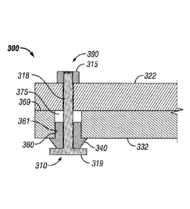
have substantially the
same size and shape as an aperture that traverses the opposing flange (e.g.,
the cover flange 322)
from the flange (e.g the base flange 332) into which the fastener receiver 340
is disposed. The
shape and size of the clearance slot of the fastener receiver 340 relative to
the base 319 allow only
a limited number of orientations for the base 319 to fit within the clearance
slot. Such an
alignment can coincide with coupling features (e.g., quick release threads)
disposed on the distal
end of the stem 318, as well as the head 315.
- 16 -
CA 3060768 2019-10-30
= =
WO 2013/165561
PCT/US2013/030214
[00651 ()nee the 'base 319 is fit within the clearance slot of the
fastener
receiver 340, the base 319 (and, thus, the rest of the fastener 310) can be
rotated along
the cam feature until the base 319 reaches the end. of the cam feature.- In
certain.
example embodiments, the slope and distance (e.g., amount of rotation) of the
Cam
feature can coincide with the slope and distance of the coupling features at
the distal
end of the stem 318.
[00661 Alternatively, if the stem 31.8 is -fixedly coupled to the
head 315, the
slope and distance of the cam feature can coincide with the optimal tension of
the
stem 318 when the base 319 has been fully rotated within the Cam feature-. In
such a
case, the base 319 can be removably coupled to the stem 318, For. example; the
base
319 can be a pin that removably couples (e.g., slides, threadably couples) to
a
receiving aperture at the end of the stem 318
10067] When the base 319 of the fastening device movably (e.g.,
rotatably)
travels to the -end ate cam feature, the stem 318 of the fastener 310 is at an
optimal
tension. Such optimal tension of the stern 318 can also, or in the
alternative, be a
result of the distal end of the stem 318 movably (e.g., rotatably, threadably)
coupling
to a coupling feature .disposed in the head 31.5. In any ease, as a result,
cover flange
322 and the base flange 332 are forced toward each other and to Close the
distance of
the flame path 369.
100681 The fastener receiver 340 can be made of one or more of a
number of
materials. Example's Of such materials can include, but are not limited to,
steel,
rubber; nylon, and aluminum. In certain example embodiments, when the fastener
receiver 340 is mechanically coupled to the fastener 310 and one or both
flanges, a. ,
flame path 369 between the cover flange 322 and the body flange 332 can meet
one or
Mote applicable Standards (e.g., flame path 369 is no greater than 0,0015
inches).
[00691 In 'certain example embodiments, the fastening device 390 of
Figure 3
and the fastening device 110 of Figures lA and I B can be used with one Or
more
example load distributing members, as described above with respect to Figures
2A.-
2C, In such a case, fewer fastening devices can be used around the perimeter
of the
explosion-proof enclosure and still maintain the flame path for the enclosure.
.
10070] Example embodiments of fastening devices for explosion-proof
enclosures resist explosion and/or hydrostatic forces by maintaining a flame
path
where the cover flange and the body flange are coupled. Further, using the
fastening
.devices described herein and other embodiments of these fastening devices
allows for
- 17 -
CA 3060768 2019-10-30
WO 2013/165561
PCT/U82013/030214
efficient and effective coupling and/or decoupling of the cover and the body
of the
explosion-proof enclosure, in addition, .using example embodiments of
faStening
devices allows for increased flexibility with regard to where components are
positioned on the cover and/or where conduit can be manually coupled to the
explosion-proof enclosure. Further, using example embodiments' of fastening
devices
for explosion-proof enclosures allows the flame path to exist within the
requirements
of one or More Standards for explosion-proof enclosures.
100711 Accordingly, many modifications and other embodiments set
Ibith
herein will, come to mind to one skilled in the art to which. fastening
devices fbr
explosion-proof enclosures 'pertain. having The benefit of the teachings
presented in the
foregoing descriptions and 'the associated drawings. Therefore, it: is to he
understood
that fastening devices fbr explosion-proOf enClosttres is not. to be liMited
to the
specific embodiments disclosed and 'that modifications and Other embodiments
are
intended to be included within the 'scope of this application. Although
specific tenns
are employed herein, they are used in a generic and descriptive sense only and
not for
purposes of limitation.
=
=
=
- g
CA 3060768 2019-10-30