Note: Descriptions are shown in the official language in which they were submitted.
MULTIFUNCTIONAL MOTORIZED BOX AND LANDING PAD FOR
AUTOMATIC DRONE PACKAGE DELIVERY
TECHNICAL FIELD OF THE INVENTION
The present document relates to the field of landing box for unmanned aircraft
vehicle (UAV). More particularly, it relates to a multifunctional motorized
box and
landing pad for automatic drone package delivery using an UAV providing a
standardized landing zone for an autonomous and/or remotely piloted UAV as
well as securing the delivered package in an efficient means. It is also
suggested a method for necessary regulation of drone traffic by managing
emergency situations (unexpected low battery, requests to land due to
mechanical problems or bad weather) and monitoring the current air traffic.
BACKGROUND
The economic sector of package delivery has undergone steady growth since the
birth of online commerce. People increasingly rely on punctual delivery for
urgent
orders which leads to increased ground delivery. In cities where the majority
of the
world population now lives, there is the prospect of a new delivery means.
Given
that high population density in these urban areas leads to shorter delivery
distance,
the use of drone delivery is desirable and makes sense economically. The
paradigm applies to consumer goods ranging from daily necessities, take-out
and
medical supplies for example.
It will be also desirable that the goods to be delivered are as near as
possible to
the customer such that the drone is not blocked from ground level traffic
constraints
and because the drone has limited cargo lift capability when compared to
ground
truck delivery. The drone is thus better suited for point-to-point delivery of
small
packages.
To achieve this, the drone delivery operation must comply with the following
requirements:
- 1 -
CA 3060808 2019-11-01
¨ A landing pad that is predicable in size and clear from any object.
¨ Provides a means for the drone to remain above ground which is less prone
to accidents with animals, children, people and other moving objects.
¨ The landing area is not buried in snow, sand, ash or other debris that
can
be blown by winds.
¨ Allows operation in areas with frost, snow or rain and high temperature.
¨ Provides theft security and neighbor discretion about a package arrival
when used in private home settings.
¨ Provides a way of keeping the delivered product in a controlled
environment, especially when food, medicine or perishable goods are
delivered. The system protects the received package from the elements and
optionally controls the enclosure's internal temperature, the holding
conditions being compatible with the order's optimal storage properties.
¨ All this is autonomous in operation.
- Provides electrical power to the drone, allowing it to charge its on-board
batteries and thus increase its accessible range.
In a broader view, allowing simultaneously multiples drone flights in an area
that
requires some control features needed by an aviation control agency:
¨ Provide a safe landing zone with possible recharge in situations when the
drone cannot maintain the established flight plan.
¨ Allow a means of managing and monitoring air traffic to avoid collisions
and
ensuring that air traffic safety rules are followed.
¨ Detecting the use of unidentified/unlicensed drones and having a means of
tracking down the operator by law enforcement.
BRIEF SUMMARY OF THE INVENTION
In accordance with a first general aspect, there is provided a multifunctional
motorized box and landing pad for automatic drone package delivery using an
unmanned aircraft vehicle. The multifunctional motorized box and landing pad
comprises a box housing; retractable flaps configurable between a closed
- 2 -
CA 3060809 2019-11-01
configuration and an open configuration; and a motorized mechanism configured
to move the retractable flaps between the closed configuration and the open
configuration. The box housing has a top edge and defines a sealable package
receiving enclosure having a closed bottom chamber including a base and at
least
one side wall projecting upwardly therefrom and an open top defining a package
inlet. The retractable flaps each have a landing pad surface and include an
inner
flap section and an outer flap section. The retractable flaps are connected to
the
box housing at the top edge thereof. In the closed configuration, the outer
flap
sections of the retractable flaps define a protective cover covering the
package
inlet and sealing the package receiving enclosure and the inner flap sections
of the
retractable flaps each extend downwardly from the top edge of the box housing,
proximate to a corresponding one of the at least one side wall of the package
receiving enclosure, with the landing pad surface of each one of the
retractable
flaps facing inwardly towards the package receiving enclosure. In the open
configuration, the inner flap sections and the outer flap sections of the
retractable
flaps together define a landing pad for the unmanned aircraft vehicle, with
the
inner flap sections covering the package inlet and closing the package
receiving
enclosure of the box housing and the landing pad surface of each one of the
retractable flaps facing outwardly for receiving the unmanned aircraft vehicle
thereon.
In accordance with another general aspect, there is provided a multifunctional
motorized box and landing pad for automatic drone package delivery using an
unmanned aircraft vehicle. The multifunctional motorized box and landing pad
comprises: a box housing; retractable flaps including an inner flap section
and an
.. outer flap section and connected to the box housing at the top edge
thereof, the
retractable flaps being configurable between a closed configuration and an
open
configuration; a motorized mechanism configured to move the retractable flaps
between the closed configuration and the open configuration; and luminous
indicators mounted to at least one of the box housing and the retractable
flaps, the
luminous indicators producing pulsed light representative of a binary signal
and
defining a final destination honing system in communication with the unmanned
- 3 -
CA 3060808 2019-11-01
aircraft vehicle. The box housing has a top edge and defines a sealable
package
receiving enclosure having a closed bottom chamber including a base and at
least
one side wall projecting upwardly therefrom and an open top defining a package
inlet. In the closed configuration, the outer flap sections of the retractable
flaps
define a protective cover covering the package inlet and sealing the package
receiving enclosure of the box housing and the inner flap sections of the
retractable
flaps each extend downwardly from the top edge of the box housing and line a
corresponding one of the at least one side wall of the package receiving
enclosure.
In the open configuration, the inner flap sections and the outer flap sections
of the
lo retractable flaps extend substantially along a common plane to define a
landing
pad for the unmanned aircraft vehicle, with the inner flap sections covering
the
package inlet and closing the package receiving enclosure of the box housing.
The final destination honing system is configured to assist in the landing and
approach of the unmanned aircraft vehicle towards the multifunctional
motorized
box and landing pad.
In accordance with another general aspect, there is also provided a
multifunctional
motorized box and landing pad for automatic drone package delivery using an
unmanned aircraft vehicle. The multifunctional motorized box and landing pad
comprises: a box housing; retractable flaps connected to the box housing at
the
top edge thereof, the retractable flaps being configurable between a closed
configuration and an open configuration; a motorized mechanism configured to
move the retractable flaps between the closed configuration and the open
configuration; and a mechanism operative to remove at least one of snow and
dust
from a surface of the retractable flaps. The box housing has a top edge and
defines
a sealable package receiving enclosure having a closed bottom chamber
including
a base and at least one side wall projecting upwardly therefrom and an open
top
defining a package inlet. In the closed configuration, the retractable flaps
define a
protective cover covering the package inlet and sealing the package receiving
enclosure of the box housing. In the open configuration, the retractable flaps
define
a landing pad for the unmanned aircraft vehicle. The mechanism for the removal
of at least one of snow and dust including at least one of heating elements
mounted
- 4 -
CA 3060808 2019-11-01
to the retractable flaps and nozzles positioned and configured to project an
air jet
to clean the surface of the retractable flaps.
In accordance with another general aspect, there is further provided a
multifunctional motorized box and landing pad for automatic drone package
delivery using an unmanned aircraft vehicle. The multifunctional motorized box
and landing pad is in data communication with a remote processing unit and
comprises a RF spectrum analyzer scanning a surrounding of the multifunctional
motorized box and landing pad to monitor a corresponding airspace. The RF
spectrum analyzer identifies RF identifiers of identified unmanned aircraft
vehicle
and defines a RF power spectrum of the corresponding airspace. The RF
identifiers of identified unmanned aircraft vehicle and the RF power spectrum
of
the corresponding airspace define RF spectrum data that can be used to
identify
unauthorized unmanned aircraft vehicles. The multifunctional motorized box and
landing also comprises a data communication system at least periodically
transmitting the RF spectrum data to the remote processing unit over a
network.
In accordance with another general aspect, there is further provided a
multifunctional box and landing pad network for monitoring unmanned aircraft
vehicles in an extended airspace. The multifunctional box and landing pad
network
comprises a plurality of multifunctional box and landing pad configured for
.. automatic package delivery using one of the unmanned aircraft vehicles.
Each
one of the plurality of multifunctional box includes retractable flaps and a
motorized
mechanism configured to move the retractable flaps between a closed
configuration and an open configuration. Each one of the plurality of
multifunctional box and landing pad is also positioned in a specific spatial
location
and monitor a corresponding local airspace. The sum of the local airspace of
each
one of the plurality of multifunctional box and landing pad defines the
extended
airspace. Each one of the plurality of multifunctional box and landing pad
comprises a RF spectrum analyzer scanning a surrounding of the corresponding
multifunctional box and landing pad to monitor a corresponding airspace
thereof.
The RF spectrum analyzer acquires RF at least one of a standard ID of each
- 5 -
Date Recue/Date Received 2022-09-16
identified unmanned aircraft vehicle of the unmanned aircraft vehicles and a
RF
power usage of each unidentified unmanned aircraft vehicles of the unmanned
aircraft vehicles in the corresponding local airspace, the at least one of
- 5a -
Date Recue/Date Received 2022-09-16
the standard ID of each identified unmanned aircraft vehicle and the RF power
usage of each unidentified unmanned aircraft vehicle in the corresponding
local
airspace defining RF identifiers of the unmanned aircraft vehicles in the
local
airspace and the combination of the RF power usage of each unidentified
unmanned
aircraft vehicle in the corresponding local airspace defining a RF power
spectrum
of the corresponding local airspace. The RF identifiers of the unmanned
aircraft
vehicles and the RF power spectrum of the corresponding airspace define RF
spectrum data. Each one of the plurality of multifunctional box and landing
pad
further comprises a data communication system at least periodically
transmitting
the RF spectrum data to a remote central processing unit over a network. The
remote central processing unit is configured to process the RF spectrum data
from
the plurality of multifunctional box and landing pad and to generate extended
RF
spectrum data of the extended airspace to perform air traffic regulation of
the
extended airspace in a centralized manner, based on the extended RF spectrum
data.
In accordance with another general aspect, there is further provided an air
traffic
regulation system of an extended airspace for unmanned aircraft vehicles. The
air
traffic regulation system comprises: a central processing unit; and a
plurality of
remote multifunctional box and landing pad configured for automatic package
delivery using the unmanned aircraft vehicles. The plurality of remote
multifunctional box and landing pad each are positioned in a specific spatial
location associated to a local airspace and are in data communication with the
central processing unit over a network. Each one of the plurality of remote
multifunctional box comprises a RF spectrum analyzer scanning the local
airspace
and acquiring at least one of a standard ID of each identified unmanned
aircraft
vehicle of the the unmanned aircraft vehicles and a RF power usage of each
unidentified unmanned aircraft vehicle of the unmanned aircraft vehicles in
the
corresponding local airspace. The at least one of the standard ID of each
identified
unmanned aircraft vehicle and the RF power usage of each unidentified unmanned
aircraft vehicle defines RF identifiers of the unmanned aircraft vehicles in
the local
airspace and the
- 6 -
Date Recue/Date Received 202 1-1 1-23
combination of the RF power usage of each unidentified unmanned aircraft
vehicles
in the corresponding local airspace defines a RF power spectrum of the
corresponding local airspace. The RF identifiers of the unmanned aircraft
vehicles
and the RF power spectrum of the corresponding airspace defines RF spectrum
data of the local airspace. Each one of the plurality of remote
multifunctional box
also comprises a data communication system at least periodically transmitting
the
RF spectrum data to the central processing unit over the network. The remote
central processing unit is configured to process the RF spectrum data from the
plurality of remote multifunctional box and landing pad and to generate
extended
RF spectrum data of the extended airspace to perform air traffic regulation of
the
extended airspace in a centralized manner, based on the extended RF spectrum
data.
BRIEF DESCRIPTION OF THE DRAWINGS
Other objects, advantages and features will become more apparent upon reading
the following non-restrictive description of embodiments thereof, given for
the
purpose of exemplification only, with reference to the accompanying drawings
in
which:
Figure 1 is a perspective view of the multifunctional motorized box and
landing
pad, in accordance with an embodiment and where retractable flaps of the
motorized box and landing pad are configured in a closed configuration, a box
housing of the multifunctional motorized box and landing pad being shown in
transparency. ___________________________________________________________
- 6a -
Date Recue/Date Received 202 1-1 1-23
Figure 2 is a perspective view of the multifunctional motorized box and
landing pad
of Figure 1, where the retractable flaps of the motorized box and landing pad
are
configured in an open configuration.
Figure 3 is a schematic representation of a functional system overview of the
multifunctional motorized box and landing pad, in accordance with an
embodiment.
Figure 4 is a state diagram of the multifunctional motorized box and landing
pad,
in accordance with an embodiment.
Figures 5a to 5d are schematic representations of alternative embodiments of
the
multifunctional motorized box and landing pad showing different possible sizes
and
shapes of the retractable flaps.
Figures 6a to 6c are schematic representations of a system overview of the
multifunctional motorized box and landing pad, in accordance with an
embodiment,
with Figure 6a showing a perspective view of the multifunctional motorized box
and
landing pad in accordance with an embodiment, Figure 6b showing an enlarged
view of a bottom section of the multifunctional motorized box and landing pad
of
Figure 6a and Figure 6c showing a schematic representation of a motorized
mechanism configured to move the retractable flaps between the closed
configuration and the open configuration, in accordance with an embodiment.
Figure 7a is a schematic representation of a retractable flap of the motorized
box
.. and landing pad, in accordance with an embodiment.
Figure 7b is a side elevation schematic representation of a motorized
mechanism
and a corresponding retractable flap, in accordance with an embodiment, with
the
retractable flap shown in the open configuration.
Figure 7c is an isometric schematic representation of a hinged mechanism of a
retractable flap for the motorized mechanism of Figure 7b.
Figure 7d is a front elevation schematic representation of a lower section of
a
motorized mechanism, in accordance with an embodiment where the motorized
mechanism includes a two-shaft motor.
- 7 -
CA 3060909 2019-3.1-01
,
DETAILED DESCRIPTION
In the following description, the same numerical references refer to similar
elements. The embodiments, geometrical configurations, materials mentioned
and/or dimensions shown in the figures or described in the present description
are
embodiments only, given solely for exemplification purposes.
Moreover, although the embodiments of the multifunctional motorized box and
landing pad and corresponding parts thereof consist of certain geometrical
configurations as explained and illustrated herein, not all of these
components and
geometries are essential and thus should not be taken in their restrictive
sense. It
is to be understood, as also apparent to a person skilled in the art, that
other
suitable components and cooperation thereinbetween, as well as other suitable
geometrical configurations, may be used for the multifunctional motorized box
and
landing pad, as will be briefly explained herein and as can be easily inferred
herefrom by a person skilled in the art. Moreover, it will be appreciated that
positional descriptions such as "above", "below", "left", "right" and the like
should,
unless otherwise indicated, be taken in the context of the figures and should
not
be considered limiting.
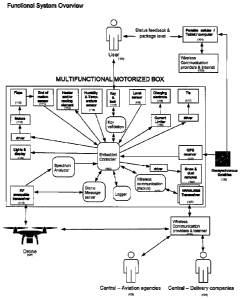
Referring to Figures 1 to 3, there is shown the multifunctional motorized box
and
landing pad (or landing box) (10) in accordance with an embodiment (Figures 1
and 2) and a functional system overview of the system including the
multifunctional
motorized box and landing pad (10) (see Figure 3). The multifunctional
motorized
box and landing pad (10) comprises a box housing (12) defining an enclosure
(14)
and having a top edge (16). The multifunctional motorized box and landing pad
(10) also includes retractable flaps (110) configurable between a closed
configuration (See fig. 1) and an open configuration (see fig. 2). As can be
seen in
figure 1 and 2, each retractable flap (110) includes an inner flap section
(110b) and
an outer flap section (110c). In the closed configuration (see figure 1), the
outer
flap sections (110c) of the retractable flaps (110) define a protective cover
closing
the enclosure (14) of the box housing (12) and the inner flap sections (110b)
of the
retractable flaps (110) extend in the enclosure (14). In the open
configuration (see
- 8 -
CA 3060808 2019-11-01
figure 2), the inner flap sections (110b) and the outer flap sections (110c)
of the
retractable flaps together define a landing pad (20), with the inner flap
sections
(110b) closing the enclosure (14) of the box housing (12). In other words, in
the
open configuration (see figure 2), the inner flap sections (110b) and the
outer flap
sections (110c) of the retractable flaps (110) extend substantially along a
common
plane to define a landing pad (20) for the unmanned aircraft vehicle, with the
inner
flap sections (110b) closing the enclosure (14) of the box housing (12).
The box (10) also includes a motorized mechanism (111 & 118) configured to
move
the retractable flaps between the closed configuration and the open
configuration.
Each one of the retractable flaps (110) has a landing pad surface (110a) and
is
pivotally connected to the box housing (12) at the top edge (16) thereof. In
the
closed configuration, the retractable flaps (110) define a protective cover
(18)
closing the enclosure (14) of the box housing (12), with the landing pad
surface
(110a) of each one of the retractable flaps (110) facing inwardly towards the
enclosure (14). In the open configuration, the retractable flaps (110) define
a
landing pad (20) for the unmanned aircraft vehicle (or drone) (107), with the
landing pad surface (110a) of each one of the retractable flaps (110) facing
outwardly for receiving the drone (107) thereon. In an embodiment, the box
(10)
includes a weatherproof gasket (26) extending along the edges of the
retractable
flaps (110).
Prior to usage, the customer (100) first registers his system with delivery
companies (104). The customer (100) can register his landing box (10) with its
ID along and its GPS coordinates acquired via a cellular phone, a tablet or a
computer (101) or via the embedded GPS receiver if equipped (106 & 122). The
customer (100) can then connect the box (10) to a standard power source. The
box (10) has posts for yard installation (see fig. 1) and anchors for balcony
use.
Standardized clearances must be respected. The box (10) may itself
communicate to the delivery company this information when enabled for internet
access through the user's private wireless communication (WiFi, cellular or
other) (105, 126 & 127).
- 9 -
CA 3060808 2019-11-01
The box (10) has retractable flaps (110) that serve a dual function of
protective
cover when closed (see fig. 1); and as a landing (20) pad when opened (see
fig. 2). To achieve this, when closed, some parts of the flaps (i.e. the
landing
pad surface (110a)) face downward in the box (10). Many embodiments of the
flaps (110) are possible (see figs. 5a to 5d). Depending on the mechanical
flap
configuration, an optional, extensible material (or enclosure cover) (22) can
be
used between the flaps (110) to provide a continuous sealed area when
deployed (i.e. when configured in the open configuration).
A motorized mechanism (111 & 118) is responsible of moving the flaps (110)
from
open to close state (or configuration) and it is commanded by embedded
electronics or computer (to move the flaps (110) from the closed state of fig.
1 to
the open state of fig. 2). Such mechanisms can be either centralized in the
box
(10) or can be independent for each flap (110). For example, in the
embodiments
shown in figures 6a, 6c, and 7a to 7d, the motorized mechanism (111 & 118)
includes a motor (118) positioned inside the box housing (12) and actuating
wires
(160) connected to corresponding sections of the flaps (110) (i.e. to an inner
flap
section (110b) and an outer flap section (110c)), to move the flaps (110) from
the
closed configuration to the open configuration and vice versa. In an
embodiment,
the wires (160) can be positioned inside a container wall (12a). In an
embodiment,
at least one pulley (181) is provided between the motor (118) and the
corresponding flap (110).
In the embodiment shown in figures 1, 2 and 6a and 7a to 7d, the flaps (110)
include the above mentioned inner flap section (110b) and outer flap section
(110c) and the motorized mechanism (111 & 118) includes a hinged mechanism
for each one of the retractable flaps (110). The hinge mechanism can include
at
least one spring loaded hinge (182) cooperating with the motor (118) and wires
(160) to move the inner flap section (110b) and outer flap section (110c) of
each
flap (110) between the open configuration and closed configuration. As can be
seen in the figures, the movement of the inner flap section (110b) and outer
flap
section (110c) includes positioning the inner flap section (110b) and outer
flap
- 10 -
CA 3060808 2019-11-01
section (110c) substantially horizontal (i.e. to extend along a common
substantially horizontal plane) when the flaps (110) are configured in the
open
configuration. In an embodiment the spring hinge (182) can force the inner
flap
section (110b) towards the inner surface of the container wall 12a and the
outer
flap section (110c) above the enclosure (14) (to close the enclosure (14) of
the
box housing (12)) when the tension of the wires (160) is released, to position
each
one of the flaps (110) in the closed configuration. In an embodiment, the
motor
(118) can be a two-shaft motor, with one shaft being associated to the wires
(160)
of each one of the inner flap section (110b) and outer flap section (110c) and
allowing a different range of movement for each one.
In an embodiment, each flap (110), on the landing pad side (110a), has one or
many non-corrosive electrodes (116) that link safely to an in-drone battery
charger. The drone (107) could use non-corrosive conductive landing gear to
make contact. The spacing and placement between electrode groups is
constructed in a manner that allows at least two different polarity/phase
contacts
for any drone landing position for a standardized landing pad distance.
Electrodes can have many forms, dots, line mesh or continuous surfaces and
may be spring loaded. Charge can be enabled upon drone request
("CHARGES"). Alternately charging may be via an inductive link.
The current limited source (128) can be DC or AC with two or more electrical
phases for allowing in-drone charging. This allows charging even if only two
electrodes make contact (116). If more than two make contact, the greater the
current may be delivered by unit of time. The current limiter (128) may also
incorporate a ground fault detector to prevent electric shock to users or
bystanders. For example, figures 6a and 6c show the current limiter (128)
installed in the landing box (10).
Optionally, each landing gear of the drone (107) may have a coil, a magnet or
a ferromagnetic material. In an embodiment, a coil or magnet is placed in
various locations in the flap (110) for allowing firm contact while charging
and
- 11 -
CA 3060908 2019-11-01
magnetically ties (117) the drone to the landing pad to prevent a fall from
high
winds or an impact. The magnetic tie down system can also be used by the
drone upon landing and started upon its command by a drone message
("TIE"). Alternately mechanically actuated anchoring may be used.
In an embodiment, lights (109) are placed on the edges of the flaps (110)
and/or in the box (10) and serve as an optical guide for the drone (107) to
make the final landing approach, thus providing a final destination honing
system allowing efficient night time operation with the drone camera. The
final
destination honing system is in communication with the drone (107) and is
io configured to assist in the landing and approach of the drone 107
towards the
box (10). In an embodiment, the luminous indicators (109) are positioned on
the
landing pad surface of the retractable flaps (110). Optionally, some of these
luminous indicators (109) may be placed inside the box (10) and their covering
parts on the flaps (110) shall then be made transparent allowing light to flow
out.
In an embodiment, the lights (109) may be pulsed by the controller (121) in a
binary manner which allows for the drone (107) via simple optical sensor or
camera use to capture the box's ID and status. Color changes may also be
utilized as to enhance guidance or as communications. Non-visible light
(infrared
or UV) may also be used instead or in addition to visible light. In other
words, the
luminous indicator can produce either visible light or invisible light.
In an embodiment, depending on the system communication and availability, the
box (10) is able to exchange communication messages either directly by a RF
transceiver (119 & 124) or by a wireless communication & internet (105,126 &
127).
Complementarily, in an embodiment, the box may have a RF transceiver (119)
that can transmit a message stack (124) continuously in addition to a
periodical
ID and status. The status is used to assist the drone's (107) navigation while
- 12 -
CA 3060809 2019-11-01
searching for the box (10) and making a landing approach. The said transceiver
(119) may be composed of directional antennas to further enhance navigation.
In an embodiment, the box may also be fitted with a multiplicity of wireless
transceivers (127) (RF, WiFi, cellular or other) that can exchange messages
with
the drone using internet, cellular or another common global network. For
example and without being limitative, figures 6a and 6c show an embedded
computer and network (184) in the landing box (10).
Referring to Figures Ito 4, to allow a box open for landing, the box (10)
receives
the message key or token from the drone (107). This key may be encrypted. If
the matching key is provided then the flaps (110) open and the box status
changes from "IDLE" to "OPENING" and the status is broadcasted to the drone
(107). When opened completely, the box (10) then broadcasts a "READY" state
indicating to the drone (107) that the pad (20) is available for landing. For
enhanced security, the computer might detect that all the flaps (110) are
correctly
is deployed in the landing pad configuration by the means of one or many
sensors
(111).
In the case that the wrong key has been given to the box, a message is
broadcasted along with visual light indications informing the drone (107) that
the
wrong box has been selected. This allows it to move on to a different target.
Once the drone (107) has landed, the package (17) is deposited and the drone
(107) clears the pad (20) the drone (107) sends a "DONE" message to the box
(10).
The controller (121) then changes its status to "CLOSING". When the flaps
close,
the package (17) falls to the bottom or onto the previous package inside the
box
( 10) (i.e. in the enclosure 14). When completed, it broadcasts the delivery
status
in the "NOTIFY" state, then returns to the "IDLE" state.
Optionally and if authorized in user settings, the box (10) may accept an
opening
request and provide a recharge service to an in-transit drone that needs
power,
- 13 -
CA 3060909 2019-3.1-01
using the previous stated procedure but using a RF universal "Emergency" or
"Charge message" pass key. Box ID & Drone ID & status are updated via the
drone's communication link. Depending of the delivery system software
configuration, the user may be credited for this event. Also, the user may
deny
this. In that situation the box will reply a denied message following such a
drone
request.
The drone relays information to delivery company's central computing system
(104) which informs both parties on the delivery status.
A level sensor detects (115) the current package level inside the box.
lo As previously mentioned, the box (10) can be linked to the internet via
WiFi or
other wireless means (105, 126 & 127). Access to the cloud allows real-time
delivery tracking, system ID, status, box fill level and delivery tracking
information. The system operates independently despite network connection
being unavailable.
In an embodiment, a temperature sensor and/or a humidity sensor (113) detects
frost conditions and starts a periodic or programmed defrost heating cycle to
prevent mechanical failure of the box opening system. In other words, the box
includes a defrost mechanism performing a defrost cycle of at least a section
of
the box (10) upon detection of frost conditions by the temperature sensor
and/or
a humidity sensor (113).
In an embodiment, a temperature sensor (113) with a heating or cooling element
(112) is also used to keep the interior of the box (110) (or box enclosure 14)
at a
required temperature until the box (10) is emptied. For example and without
being limitative, figures 6a and 6b show a heater and/or Pelletier which can
be
used as heating or cooling element (112). The required temperature and the
control duration limit are sent by the delivery companies (104) via the drone
(107)
or the wireless communication (105) when delivering the package (17).
- 14 -
CA 3060808 2019-11-01
,
In an embodiment, the box has an electronic and/or mechanical key (114 & 123)
allowing opening of the box 10 for package retrieval. All accesses made are
logged by the device (125); more than one user may have access.
In an embodiment, mechanisms for the removal or melting of snow and dust (or
snow removal mechanism) (108) may be optionally integrated in the form of
compressed air jet or heating elements integrated into the surface (i.e. into
the
retractable flaps to clean a surface thereof).
In an embodiment, the box may have a display (109) for showing the user's
current package level and status.
In an embodiment, the RF drone's ID and RF power spectrum may serve to
regulate air traffic in a centralized manner. The box could be equipped with
wide band RF spectrum analyzer/scanner (119 & 120) that can report to
aviation regulation agency (103) the RF power spectrum surrounding the box
and also all standard drone ID and RF power data through a local WiFi or
wireless connection (105, 126 & 127), using a data communication system.
The agency then has access to all boxes data from different spatial locations,
thus allowing triangulations of both identified (by ID) and unidentified (by
RF
spectrum usage) drone signature and positions. This allows real-time
monitoring and possible signature requests from an agency's command
center. Also, real-time and historical positioning data that can be used by
law
enforcement in the case of an illegal usage of drones.
A more complete box behavior is depicted using the state diagrams in fig 4.
The box is initially delivered in an "UNCONFIGURED" state as it waits for data
user (100) inputs from a computer, cellular or tablet (101) via the wireless
link
(105) (GPS position confirmation, customer ID, preferences, etc). When the
information is received and accepted by the delivery company (104), the box
is set to an "IDLE" using similar means. For all status broadcasts the box ID
and status are sent via local RE (119), the same information along with the
local RF spectrum are sent (126) via the wireless network (127) when
- 15 -
CA 3060808 2019-11-01
available. In the "IDLE" state only, the box listens for a drone message
(Drone
key) or a user input (User key). Upon reception of a valid key, it goes into
the
"OPENING" state and checks flaps movement progression. When flaps are
confirmed to be fully extended, the status progresses to "READY" (if it was
trigged by a drone) or to "USER OPEN" (if triggered by a user key). In the
"READY" state, the drone is assisted by the box in its final approach by both
lights (109) and by RF signals (119). Once it has landed, or prior to arrival,
the drone may request the states "TIE" (117) then "CHARGE" (116). The
drone may leave the package and when it has taken off it sends a "Done"
lo message which makes the box go into the "CLOSING" state. If any error
occurs during the "OPENING" or "CLOSING" states, the box retries then
enters a "FAILURE" status if it cannot complete. The "NOTIFY" state sends a
message to both delivery company (104) and user (100) about the delivery
and the box status. If a "FAILURE" state occurs, the box is set to the
"UNAVAILABLE" state rather than "IDLE". The user can toggle between those
two states ("UNAVAILABLE", "IDLE") from a user key (114) or from a
computer, cellular or tablet (101) using the wireless link (105).
Although the embodiments as illustrated in the accompanying drawings comprises
particular steps of a method and although the embodiment of the system
explained
and illustrated herein include particular components, not all of these
components
and steps are essential and thus should not be taken in their restrictive
sense. It is
to be understood, as also apparent to a person skilled in the art, that other
suitable
components, and cooperation therebetween, as well as other suitable
configurations may be used for the method and system, as will be briefly
explained
herein and as can be easily inferred herefrom, by a person skilled in the art,
without
departing from the scope of the invention.
- 16 -
CA 3060808 2019-11-01