Note: Descriptions are shown in the official language in which they were submitted.
SINGLE-INSERTION, MULTIPLE SAMPLE BIOPSY DEVICE WITH INTEGRATED
MARKERS
[0001]
Field of the Invention
[0002] This invention relates to a tissue biopsy sampling device.
Background of the Invention
[0003] Often, it is either desirable or necessary to obtain specimens of
tissue from humans and
other animals, particularly in the diagnosis and treatment of patients with
cancerous tumors,
premalignant conditions, and other diseases or disorders. For example, when it
is discovered that
suspicious conditions exist, either by means of x-ray or ultrasound imaging in
various tissues of
the body, a physician typically performs a biopsy to determine if the cells at
the suspected site are
cancerous.
[0004] A biopsy can be done either by an open or percutaneous technique. Open
biopsy is an
invasive procedure using a scalpel, whereby either a portion (incisional
biopsy) or the entire mass
(excisional biopsy) is removed. Percutaneous biopsy is usually done with a
needle-like instrument
through a relatively small incision, and can be performed by fine needle
aspiration (FNA) or
through the taking of a core biopsy sample. In FNA biopsy, individual cells or
clusters of cells are
obtained for cytologic examination and can be prepared such as in a
Papanicolaou smear. In a core
biopsy, a core or fragment of the tissue is obtained for histologic
examination.
[0005] Intact tissue from the organ, lesion, or tumor is preferred by medical
personnel in order to
arrive at a definitive diagnosis regarding the patient's condition. In most
cases only part of the
tissue in question needs to be sampled. The portions of tissue extracted must
be indicative of the
organ, lesion, or tumor as a whole. Often, multiple tissue samples from
various locations of the
mass being sampled may be taken.
[0006] The percutaneous biopsy procedure can be performed utilizing various
techniques and
devices. One such biopsy device can include an inner stylet positioned inside
a cutting
1
Date Recue/Date Received 2021-05-18
CA 02952566 2016-12-21
cannula, whereby the stylet is able to slide into and out of the cannula. The
stylet can be a
solid, pointed needle having a tissue sampling recess, and the cannula can be
a hollow, open-
ended needle having a sharp tip. The stylet and cannula can be manipulated
cooperatively to
capture a tissue sample in the sample recess. Such existing devices can be
manually operated,
semi-automated, and automated.
[0007] US Patent No. 6,485,436 shows a multiple sample biopsy needle with a
hydraulic
mechanism that circulates fluid from the tip of the needle back to a receiving
basket or
baskets. A revolver-type array of receiving chambers is disclosed.
[0008] US Patent No. 5,827,305 shows a tissue sampling needle that pushes a
sample
proximally using a saline wash. Samples remain spaced apart within the needle
such that the
sequence of their collection is preserved. Samples can also be removed from a
port while the
needle remains in place. No mechanical transport mechanisms or drives are
disclosed.
[0009] US Patent No. 5,526,822 shows a transport system that uses a cannula
and knock-out
pin combined with a vacuum source to shuttle a tissue sample to a multiple-
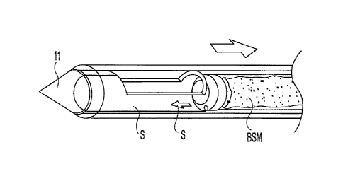
chamber cassette
where it is knocked out. The cannula is then repositioned for another sample.
The vacuum
source is external. A revolving sample cassette is also shown. A vent opening
in each
sample cylinder of the cassette is provided to eject the fluid used to
transport the tissue
sample. A removable disposable needle-bearing cassette interfaces with rotary
and linear
drives by means of long gears and shuttles that cradle the gears. Cutters
operate in rotary and
linear fashion (a counter-rotating cutters embodiment is included) and the
cannula can be
rotated to orient the sample opening.
100101 US Patent No. 6,017,316 shows a transport system similar to US Patent
No. 5,827,822
in which a cutter transports with vacuum assist. Multiple sampling with single
insertion is
described but not automated multiple sample-handling. The details of a drive
system are not
disclosed
[0011] US Patent No. 6,193,673 shows a needle with a durable part and a
disposable part.
An external cutting cannula rotates and advances axially to cut a sample. The
tissue cutter is
driven axially by a rack and pinion drive which are part of a durable
component. A cradle
connects the rack to the cutting cannula.
[0012] US Patent No. 5,944,673 describes a tissue extractor that rotates
within a piercing
needle to align with any one of multiple receiving ports while obstructing the
remaining
ports. The tissue sample is cut by advancing the cutter and removing by
withdrawing the
2
CA 3060814 2019-11-01
CA 02952566 2016-12-21
extractor. A vacuum holds the tissue sample in place during the removal of the
tissue
extractor from the cutter. The cutter rotates as it advances.
[0013] It is known to obtain a single sample with a single insertion. However,
there are
circumstances where there may be a need to obtain more than one samples. While
the known
biopsy needle can be re-inserted multiple times, such technique can cause pain
and scarring
of the body site.
[0014] It is known to leave a marker at the biopsied site. To do so, however,
a physician or
healthcare provider would typically need to withdraw the biopsy needle and
insert a different
device to leave a marker at the biopsied site. The additional step and device
may not allow
the marker to be deposited at the actual biopsied site, which can lead to
inaccurate post-
biopsy diagnosis.
Summary of the Invention
[0015] The present invention provides for exemplary embodiments of a single-
insertion,
multiple sample biopsy device. The present invention also provides for
exemplary
embodiments of a single-insertion, multiple sampling device with integrated
marker release.
[0016] In one aspect, a single-insertion, multiple sample biopsy device is
provided that
includes a stylet, a cannula, a plurality of lumens including flexible and
rigid portions, first
and second bullcheads, and a transport subassembly. The stylet extends along a
longitudinal
axis between a distal end and a proximal end, the stylet having a tip at the
distal end and a
hollow interior volume extending from a biopsy port proximate the distal end
to the proximal
end. The cannula surrounds a portion of the stylet and is movable along the
longitudinal axis.
The plurality of lumens is disposed in the interior volume. The rigid lumen is
coupled to one
of the plurality of lumens. The first bulkhead is disposed near the proximal
end. The first
bulkhead is coupled to the lumens and a second bulkhead disposed near the
distal end. The
second bulkhead is coupled to the rigid lumen, and both bulkheads define a
biopsy sample
volume. The transport subassembly is coupled to the first and second bulkheads
to move a
biopsy sample from the biopsy port to the proximal end of the stylet.
[0017] In yet another aspect, a single-insertion, multiple sample biopsy
device is provided
that includes a stylet, cannula, sleeve, lumen, bulkhead and transport
subassembly. The stylet
extends along a longitudinal axis between a distal end and a proximal end. The
stylet has a
tip at the distal end and a hollow interior volume that extends from a biopsy
port proximate
3
CA 3060814 2019-11-01
CA 02952566 2016-12-21
the distal end to the proximal end. The cannula surrounds a portion of the
stylet and is
movable along the longitudinal axis. The sleeve is disposed between the stylet
and the
cannula. The lumen is disposed in the interior volume of the stylet. The
bulkhead is coupled
to a distal end of the lumen. The transport subassembly is coupled to the
lumen and the
sleeve to move the bulkhead and sleeve relative to each other along the
longitudinal axis
between the proximal and distal ends. Preferably, at least a portion of the
lumen is flexible.
[0018] In yet a further aspect, a method of sampling biological tissue with a
biopsy device is
provided. The device has a tissue trough coupled to at least one lumen
disposed in a needle
that extends along a longitudinal axis between a distal end and a proximal
end. The method
can be achieved by: capturing a biological sample in longitudinal aperture
defined on a
circumference of the needle; and translating said at least one lumen through
the interior of the
needle to transport the biological sample from the distal to the proximal
ends.
[0019] According to an embodiment, the invention is a single-insertion,
multiple sample
biopsy device with a stylet extending along a longitudinal axis between a
distal end and a
proximal end. The stylet can have a tip at the distal end and a hollow
interior volume
extending from a biopsy port proximate the distal end to the proximal end. A
cannula
surrounds a portion of the stylet and is movable along the longitudinal axis.
There are
lumens in the interior volume. A first bulkhead is disposed near the proximal
end and coupled
to the lumens. A second bulkhead is disposed near the distal end and coupled
to one of the
lumens. Both bulkheads defines a biopsy sample volume. A transport subassembly
is
coupled to the first and second bulkheads to move a biopsy sample from the
biopsy port to
the proximal end of the stylet.
[0020] The transport subassembly preferably includes one or both of a vacuum
and
pressurized fluid supply in fluid communication with one of the lumens and a
pulley coupled
to the bulkheads and lumens to move the bulkheads and lumens along the
longitudinal axis as
a single unit. The first bulkhead is preferably configured to confront the
interior surface of
the stylet and the second bulkhead preferably is configured to permit fluid
flow between the
outer perimeter of the bulkhead and the interior surface of the stylet.
[0021] According to another embodiment, the invention is a single-insertion,
multiple sample
biopsy device that includes a stylet extending along a longitudinal axis
between a distal end
and a proximal end. The stylet has a tip at the distal end. A hollow interior
volume extends
from a biopsy port proximate the distal end to the proximal end. A cannula
surrounds a
4
CA 3060814 2019-11-01
CA 02952566 2016-12-21
portion of the stylet and is movable along the longitudinal axis. A sleeve is
disposed between
the stylet and the cannula. A lumen is disposed in the interior volume of the
stylet. A
bulkhead is coupled to a distal end of the lumen. A transport subassembly is
coupled to the
lumen and the sleeve to move the bulkhead and sleeve relative to each other
along the
longitudinal axis between the proximal and distal ends.
[0022] Preferably, the transport subassembly includes a first pulley coupled
to the sleeve via
a member and a second pulley coupled to the bulkhead via the lumen. Also,
preferably, the
member is in fluid communication with a pressurized saline source and the
lumen is in fluid
communication with one or more of a vacuum and pressurized fluid source. The
stylet tip
can have a marker one of the tip and a bulkhead disposed in the stylet. The
marker is ejected
from at least one of the tip and the bulkhead in an operative condition of the
device.
[0023] Preferably, the stylet tip includes a marker mounted on the outer
surface of the tip.
The marker is separated from the tip in an operative condition of the device.
The marker is
one or more of a hooked marker, helical marker and serrated edge marker. The
marker can
also be an annular marker or a split-ring marker.
[0024] According to another embodiment, the invention is a method of sampling
biological
tissue with a biopsy device that has a tissue trough coupled to at least one
lumen disposed in a
needle that extends along a longitudinal axis between a distal end and a
proximal end. The
method can be achieved by: capturing a biological sample in longitudinal
aperture defined on
a circumference of the needle; translating the at least one lumen through the
interior of the
needle to transport the biological sample from the distal to the proximal
ends. The translating
includes filling the trough defined by the interior surface of the needle is
disposed about a
sliding bulkhead with a bio compatible fluid.
[0025] According to another embodiment, the invention is a biopsy device with
a stylet that
extends along a longitudinal axis between a distal end and a proximal end. The
stylet has a
sample opening and an interior volume adjacent its distal end, the opening
providing access
to the interior volume. A longitudinal cutting member with a cutting edge is
movable with
respect to the stylet such that the cutting edge can cross over the sample
opening to cut a
tissue sample from a host. At least one lumen inside the stylet and movable
along the
longitudinal axis has a distal bulkhead at a distal end of the interior
volume. A transport
subassembly coupled to the at least one bulkhead moves a tissue sample from
the sample port
to the proximal end of the stylet. There is a proximal bulkhead at a proximal
end of the
5
CA 3060814 2019-11-01
CA 02952566 2016-12-21
interior volume. The transport subassembly includes a motor-drivable pulley
with the at least
one lumen wrapping at least partly around the motor-drivable pulley. A saline
pump is
connected to the at least one lumen which has an outlet in communication with
the interior
volume.
[0026] According to an embodiment, the invention is a single-insertion,
multiple sample
biopsy device with a stylet extending along a longitudinal axis between a
distal end and a
proximal end. The stylet has a tip at the distal end and a hollow interior
volume extending
from a biopsy port proximate the distal end to the proximal end. A cannula
surrounds a
portion of the stylet and is movable along the longitudinal axis. A plurality
of lumens are
located in the interior volume. A first bulkhead is located near the proximal
end. The first
bulkhead is coupled to the lumens. A second bulkhead is located near the
distal end. The
second bulkhead is coupled to the one of the lumens. Both bulkheads define a
biopsy sample
volume. A transport subassembly is coupled to the first and second bulkheads
to move a
biopsy sample from the biopsy port to the proximal end of the stylet.
[0027] Preferably, the transport subassembly includes one or both of vacuum
and pressurized
fluid supply in fluid communication with one of the lumens and a pulley
coupled to the
bulkheads and lumens to move the bulkheads and lumens along the longitudinal
axis as a
single unit. Also, preferably, the first bulkhead is configured to confront
the interior surface
of the stylet and the second bulkhead is configured to permit fluid flow
between the outer -
perimeter of the bulkhead and the interior surface of the stylet.
[0028] According to another embodiment, the invention is single-insertion,
multiple sample
biopsy device that includes a stylet extending along a longitudinal axis
between a distal end
and a proximal end. The stylet has a tip at the distal end and a hollow
interior volume
extending from a biopsy port proximate the distal end to the proximal end. A
cannula
surrounds a portion of the stylet and movable along the longitudinal axis. A
sleeve is located
between the stylet and the cannula and a lumen is located in the interior
volume of the stylet.
A bulkhead is coupled to a distal end of the lumen. A transport subassembly is
coupled to the
lumen and the sleeve to move the bulkhead and sleeve relative to each other
along the
longitudinal axis between the proximal and distal ends.
[0029] Preferably, the transport subassembly includes a first pulley coupled
to the sleeve via
a member and a second pulley coupled to the bulkhead via the lumen. The member
can be in
fluid communication with a pressurized saline source and the lumen is in fluid
6
CA 3060814 2019-11-01
CA 02952566 2016-12-21
communication with one or more of a vacuum and pressurized fluid source.
Preferably, also,
the stylet tip includes a marker located in one of the tip and a bulkhead
located in the stylet.
The marker is ejected from at least one of the tip and the bulkhead in an
operative condition
of the device.
[0030] In a variation, the stylet tip includes a marker mounted on the outer
surface of the tip,
the marker is separated from the tip in an operative condition of the device.
The marker can
be one or more of a hooked marker, helical marker and serrated edge marker.
The marker
can be an annular marker or a split-ring marker.
[0031] According to another embodiment, the invention is a method of sampling
biological
tissue with a biopsy device that has a tissue trough coupled to at least one
lumen located in a
needle that extends along a longitudinal axis between a distal end and a
proximal end. The
method can be achieved by capturing a biological sample in longitudinal
aperture defined on
a circumference of the needle and translating the at least one lumen through
the interior of the
needle to transport the biological sample from the distal to the proximal
ends. Preferably the
method is such that translating is done by filling the trough defined by the
interior surface of
the needle located about a sliding bulkhead with a bio compatible fluid.
[0032] According to an embodiment, the invention is a biopsy device with a
stylet extending
along a longitudinal axis between a distal end and a proximal end. The stylet
has a sample
opening and an interior volume adjacent its distal end, the opening providing
access to the
interior volume. A longitudinal cutting member has a cutting edge and is
movable with
respect to the stylet such that the cutting edge can cross over the sample
opening to cut a
tissue sample from a host. There is at least one lumen inside the stylet and
movable along the
longitudinal axis. The lumen has a distal bulkhead at a distal end of the
interior volume. A
transport subassembly is coupled to the at least one bulkhead to move a tissue
sample from
the sample port to the proximal end of the stylet. Preferably, a proximal
bulkhead is located
at a proximal end of the interior volume. The transport subassembly includes a
motor-
drivable pulley, the at least one lumen wrapping at least partly around the
motor-drivable
pulley. A saline pump is preferably connected to the at least one lumen, the
lumen having an
outlet in communication with the interior volume.
[0033] According to an embodiment, the invention is a single-insertion,
multiple sample
biopsy device, with a carmula forming at least part of an insertable biopsy
needle. The
cannula has a distal end where samples are received and a proximal end where
samples are
7
CA 3060814 2019-11-01
CA 02952566 2016-12-21
recovered. A shuttle mechanism, includes a distal bulkhead within the cannula.
The distal
bulkhead is connected to a fluid line. A mechanism feeds and retracts
incremental portions of
the fluid line. The fluid line is sufficiently stiff, as well as supported by
the cannula, to allow
the distal bulkhead to be pushed through the cannula, thereby to advance and
withdraw the
distal bulkhead within the cannula, whereby samples placed on a proximal side
of the distal
bulkhead are urged in a proximal direction by the distal bulkhead.
[0034] Preferably, the fluid line is connected to a vacuum pump at its
proximal end.
Preferably, the fluid line is connected to a saline pump at its proximal end.
A proximal
bulkhead is preferably located proximally of the distal bulkhead and connected
attached to
the fluid line. A vacuum line opens to a distal side of the proximal bulkhead.
The fluid line
opens to a distal side of the distal bulkhead. The distal bulkhead has at
least one opening
permitting flow from its distal side to flow backward toward its proximal
side.
[0035] Preferably, there is a sample receiving chamber located at the proximal
end. The
receiving chamber is preferably adapted to receive and separate multiple
samples, by
employing such as a carousel configuration where samples drop into recesses
and the
chamber is rotated. An intermediate sheath is preferably provided in the
cannula. The fluid
line is connected to the distal bulkhead by a manifold that fluidly couples
the fluid line to an
. annular space between the cannula and intermediate sheath.
[0036] According to an embodiment, the invention is a method of sampling
biological tissue
with a biopsy device that has a cutting sheath surrounding an intermediate
sheath which
surrounds a cannula. The cannula has a distal end with a port where tissue
samples are
received and a proximal end where samples are delivered. The cannula carries a
movable
bulkhead within it. The bulkhead is connected to a suction tube. An annular
space is defined
between the intermediate sheath and the cannula. The method of employing this
apparatus
includes: drawing a vacuum in the suction tube to suck a sample into the
cannula distal end
while the bulkhead is in a distal position in the cannula and moving the
bulkhead proximally
while fluid is forced through the annular space toward the cannula distal end
and back
through the cannula to transport the resected sample to the proximal end.
Preferably the
method includes covering the sample with the intermediate sheath. Preferably
the method
includes moving the intermediate sheath progressively with the sample.
Preferably the
method includes moving the bulkhead progressively with the intermediate sheath
and the
sample. Also, preferably, the method includes holding the intermediate sheath
in a retracted
8
CA 3060814 2019-11-01
CA 02952566 2016-12-21
position proximal of the port while drawing the vacuum and extending the
cutting sheath by
extending the cutting sheath over the port. The intermediate sheath is then
extended over the
port to cover the severed sample partly and the bulkhead retracted while
pumping fluid
distally through the annular space and proximally through the cannula to
transport the
sample.
[0037] According to an embodiment, the invention is a single-insertion,
multiple sample
biopsy device with a cutting sheath, an intermediate sheath, and a cannula all
is coaxially
aligned with the cutting sheath surrounding the intermediate sheath and the
intermediate
sheath surrounding the cannula. An annular space is defined between the
intermediate sheath
and the cannula. The cannula has a distal end with a port where tissue samples
are received
and a proximal end where samples are delivered. The intermediate sheath is
movable relative
to the cannula to selectively open and close the port. The cannula carries a
movable bulkhead
within it, the bulkhead being connected to a suction tube. A drive mechanism
forces the tube
along the cannula to move the bulkhead distally and proximally. A fluid
pumping
mechanism pumps fluid into the annular space when the intermediate sheath
partly covers the
port, thereby causing fluid to enter the port at a distal end thereof and flow
along the cannula
in a proximal direction.
[0038] Preferably, the drive mechanism and fluid pumping mechanism are
operable in
concert to move the intermediate sheath to partly cover the port, to move the
bulkhead
proximally, and to convey fluid along the annular space to the port thereby
forcing a sample
toward the proximal direction. Also, preferably, the biopsy device includes a
vacuum pump
connected to the suction tube.
[0039] According to another embodiment, the invention is a biopsy device with
a stylet that
has a sample extraction portion and a sample recovery position. A first
bulkhead engages
with, and is movable along, the stylet. A drive member attaches to the first
bulkhead to move
the first bulkhead between the sample extraction portion and the sample
recovery position. A
fluid conveyance conveys fluid into the stylet as the first bulkhead is moved
from a position
distal of the sample extraction portion to the sample recovery position
sufficient to lubricate a
tissue sample engaged by the first bulkhead as it the sample is moved along
the stylet
[0040] Preferably, the fluid conveyance generates a flow of fluid at a rate,
the rate being
lower than a rate required to force a tissue sample along the stylet by
hydraulic pressure.
Also, preferably, the drive member includes a lumen running along the stylet,
the lumen
9
CA 3060814 2019-11-01
CA 02952566 2016-12-21
forming a portion of the fluid conveyance. Also preferably, the fluid
conveyance includes a
lumen within the drive member. Also preferably, the device includes a
frictional drive
member that engages the drive member and moves it along the stylet. In another
embodiment, the second bulkhead attaches to the drive member and is located
proximal of
the first bulkhead, the first and second bulkheads defining a sample recess
between them.
[0041] According to yet another embodiment, a biopsy device has a stylet
having a sample
extraction portion and a sample recovery position. A drive member is movable
between the
sample extraction portion and the sample recovery position. A fluid conveyance
conveys
fluid into the stylet as the drive member is moved from a position distal of
the sample
extraction portion to the sample recovery position sufficient to lubricate a
tissue sample
engaged by the first bulkhead as it the sample is moved along the stylet.
Preferably, the fluid
conveyance generates a flow of fluid at a rate, the rate being lower than a
rate required to
force a tissue sample along the stylet by hydraulic pressure. Also, the drive
member
preferably includes a lumen running along the stylet, the lumen forming a
portion of the fluid
conveyance. Preferably, the fluid conveyance includes a lumen within the drive
member.
More preferably, a frictional drive member engages the drive member and moves
it along the
stylet.
[0042] According to yet another embodiment, a biopsy device has a stylet
having a sample
extraction portion and a sample recovery position. A drive member is movable
between the
sample extraction portion and the sample recovery position. A fluid conveyance
conveys
fluid into the stylet as the drive member is moved from a position distal of
the sample
extraction portion to the sample recovery position sufficient to fill an
expanding space
remaining distal of the drive member as the drive member moves from the sample
extraction
portion to the sample recovery position. Preferably, the fluid conveyance
generates a flow of
fluid at a rate, the rate being lower than a rate required to force a tissue
sample along the
stylet by hydraulic pressure. Also, the drive member preferably includes a
lumen running
along the stylet, the lumen forming a portion of the fluid conveyance.
Preferably, the fluid
conveyance includes a lumen within the drive member. More preferably, a
frictional drive
member engages the drive member and moves it along the stylet.
[0043] In the above-described embodiments, a vacuum source and a power source
can be
provided in a self-contained hand-held biopsy device. In all of the methods, a
biopsy unit can
CA 3060814 2019-11-01
CA 02952566 2016-12-21
contain a controller programmed to execute the methods automatically or
contingent on
consecutive command being entered through the biopsy device.
[0044] In the above-described embodiments, the one or more lumens extending
through the
needle (e.g., the stylet) can be, and preferably are, rigid along their length
within the needle
and flexible only along portions that are required to bend. This ensures that
the lumens can
be used to push the corresponding transport members (e.g., bulkhead(s)) for
multiple
sampling. In this case, flexible is intended to encompass piece-wise flexible
(i.e., a
combination of rigid portions linked by flexible or hinged joints) such as
fluid conveyances
that are made up with multiple hinged elements as links in a chain. There are
known and
commercially available devices that flex but provide fluid-tight flow
channels.
100451 In addition, the rigidity of the lumens can be derived from a secondary
element that
houses the lumen to give it rigidity, meaning a rigid portion of a lumen does
not need to be a
monolithic structure and the uses of terms such as "rigid lumen" or "rigid
portion of a lumen"
are not intended to limit the identified lumen structures to single-element
structures. For
example, a flexible lumen can be guided by a rigid member (for example it can
slide within a
tube) giving it all the effective rigidity needed to enable the lumen to move
a transport
member distally within a needle. Or a flexible tube can have a moving rigid
guide (tube or
other structure) to which it is fixedly attached, to give it all the effective
rigidity needed to
enable the lumen to move a transport member distally within a needle.
[0046] In addition, also in the above-described embodiments, instead of
winding the
proximal end or ends of the lumen or lumens around a pulley, the lumens can be
folded,
accordion-fashion at their proximal ends and a drive employed to move the
lumens along the
needle (e.g., the stylet). The drive can be a pair of opposing rotating drive
wheels that press
against the proximal portion of the lumen (or a member attached to the lumen)
and
frictionally engage a portion of the lumen or a structure attached to it to
drive the lumen
along the stylet. Alternatively a capstan drive could be used with the lumens
winding
partially around it.
[0047] While in most of the embodiments described, a pair of lumens are
described, one for
vacuum and one for fluid, a single lumen providing vacuum at one time and
fluid at another
time could be employed. A switching mechanism provided at the proximal end
could allow
this alternative. In this case, the drive mechanism for the bulkheads would
function as
described with a single lumen running along the stylet rather than two.
11
CA 3060814 2019-11-01
CA 02952566 2016-12-21
[00481 Although in most of the disclosed embodiments, fluid is provided to the
distal end
of the needle and permitted to flow proximally as the tissue sample is
transported
proximally, the fluid itself need not, and in embodiments, preferably is not,
sufficient in
quantity or velocity to move the tissue sample. That is, preferably, the fluid
rate does not
produce enough drag on the sample, given the seal between the sample and the
stylet, the
fluid flow rate, and the hydrodynamic properties of the sample, to transport
the sample
along the stylet. The fluid is preferably provided to flood the sample chamber
and
lubricate the passageway for transport. In addition the fluid may be only
sufficient to fill
in the space behind the bulkhead or bulkheads so that they, and the tissue,
move more
freely without creating any vacuum, even momentarily, in their wake.
Preferably, the
bulkheads described in the disclosed embodiments to not form a seal with the
stylet or
cannula. In this way fluid can flow around them easily. In fact, the fluid
used to lubricate
movement of the bulkhead(s) and sample may be provided at the middle of the
sample
chamber or proximal of the sample chamber and allowed to flow around the
bulkheads to
aid in transporting and preventing a vacuum.
100491 In addition to the transport function, the fluid also provides a
cleaning function;
clearing bits of tissue sample or aspirated material from the host from the
stylet. In an
embodiment that is a self-contained handheld, as is the preferred embodiment,
the
quantity of fluid should be minimal, but in other embodiments where large
amounts of
fluid can be provided, the fluid flush can be substantial and continue for a
long interval
after the sample is received at the recovery location.
[0049a1 In an aspect, the present invention relates to a single-insertion,
multiple sample
biopsy device, comprising: a stylet extending along a longitudinal axis
between a distal
end and a proximal end, the stylet having a tip at the distal end and a hollow
interior
volume extending from a biopsy port proximate the distal end to the proximal
end; a
cannula that surrounds a portion of the stylet and movable along the
longitudinal axis; a
plurality of lumens disposed in the interior volume; a first lumen coupled to
one of the
plurality of lumens; a first bulkhead disposed near the proximal end, the
first bulkhead
being coupled to the lumens and a second bulkhead disposed near the distal
end, the
second bulkhead being coupled to the first lumen, both bulkheads defining a
biopsy
12
CA 3060814 2019-11-01
CA 02952566 2016-12-21
sample volume; and a transport subassembly coupled to the first and second
bulkheads to
move a biopsy sample from the biopsy port to the proximal end of the stylet.
[0049b] In an aspect, the present invention relates to a single-insertion,
multiple sample
biopsy device that includes: a stylet extending along a longitudinal axis
between a distal end
and a proximal end, the stylet having a tip at the distal end and a hollow
interior volume
extending from a biopsy port proximate the distal end to the proximal end; a
cannula that
surrounds a portion of the stylet and movable along the longitudinal axis; a
sleeve disposed
between the stylet and the cannula; a lumen disposed in the interior volume of
the stylet; a
bulkhead coupled to a distal end of the lumen; and a transport subassembly
coupled to the
lumen and the sleeve to move the bulkhead and sleeve relative to each other
along the
longitudinal axis between the proximal and distal ends.
[0049c1 In an aspect, the present invention relates to the use of a biopsy
device for sampling
biological tissue, wherein the biopsy device has a tissue trough coupled to at
least one lumen
disposed in a needle that extends along a longitudinal axis between a distal
end and a
proximal end, the needle having a longitudinal aperture defined on its
circumference and
configured to capture a biological sample and wherein the biological sample is
transported
from the distal to the proximal ends through translation of the at least one
lumen through the
interior of the needle.
[0049d] In an aspect, the present invention relates to a biopsy device
comprising: a stylet
extending along a longitudinal axis between a distal end and a proximal end,
the stylet having
a sample opening and an interior volume adjacent its distal end, the opening
providing access
to the interior volume; a longitudinal cutting member with a cutting edge, the
cutting member
being movable with respect to the stylet such that the cutting edge can cross
over the sample
opening to cut a tissue sample from a host; at least one lumen inside the
stylet and movable
along the longitudinal axis, the lumen having a distal bulkhead at a distal
end of the interior
volume; and a transport subassembly coupled to the at least one bulkhead to
move a tissue
sample from the sample port to the proximal end of the stylet.
1 2a
CA 3060814 2019-11-01
CA 02952566 2016-12-21
[0049e] In an aspect, the present invention relates to a single-insertion,
multiple sample
biopsy device, comprising: a cannula forming at least part of an insertable
biopsy needle, the
cannula having a distal end where samples are received and a proximal end
where samples
are recovered; a shuttle mechanism including a distal bulkhead within the
cannula, the distal
bulkhead being connected to a fluid line; and a mechanism that feeds and
retracts incremental
portions of the fluid line, the fluid line being sufficiently stiff, as well
as supported by the
cannula, to allow the distal bulkhead to be pushed through the cannula,
thereby to advance
and withdraw the distal bulkhead within the cannula, whereby samples placed on
a proximal
side of the distal bulkhead are urged in a proximal direction by the distal
bulkhead.
[004919 In an aspect, the present invention relates to the use of a biopsy
device for sampling
biological tissue, wherein the biopsy device has a cutting sheath surrounding
an intermediate
sheath which surrounds a cannula, the cannula having a distal end with a port
where tissue
samples are received and a proximal end where samples are delivered, the
cannula carrying a
movable bulkhead within it, the bulkhead being connected to a suction tube, an
annular space
being defined between the intermediate sheath and the cannula, wherein drawing
a vacuum in
the suction tube allows to suck a sample into the cannula distal end while the
bulkhead is in a
distal position in the cannula; and wherein movement of the bulkhead
proximally while fluid
is conveyed through the annular space toward the cannula distal end and back
through the
cannula allows for transportation of a resected sample to the proximal end.
[0049g] In an aspect, the present invention relates to a single-insertion,
multiple sample
biopsy device, comprising: a cutting sheath, an intermediate sheath, and a
cannula, all being
coaxially aligned with the cutting sheath surrounding the intermediate sheath
and the
intermediate sheath surrounding the catmula, an annular space being defined
between the
intermediate sheath and the cannula; the cannula having a distal end with a
port where tissue
samples are received and a proximal end where samples are delivered; the
intermediate
sheath being movable relative to the cannula to selectively open and close the
port; the
cannula carrying a movable bulkhead within it, the bulkhead being connected to
a suction
tube; a drive mechanism that forces the tube along the cannula to move the
bulkhead distally
and proximally; and a fluid pumping mechanism to pump fluid into the annular
space when
12b
CA 3060814 2019-11-01
CA 02952566 2016-12-21
the intermediate sheath partly covers the port, thereby causing fluid to enter
the port at a
distal end thereof and flow along the cannula in a proximal direction.
[0049h] In an aspect, the present invention relates to a biopsy device,
comprising: a stylet
having a sample extraction portion and a sample recovery position; a first
bulkhead engaged
with, and movable along, the stylet; a drive member attached to the first
bulkhead to move
the first bulkhead between the sample extraction portion and the sample
recovery position;
and a fluid conveyance to convey fluid into the stylet as the first bulkhead
is moved from a
position distal of the sample extraction portion to the sample recovery
position sufficient to
lubricate a tissue sample engaged by the first bulkhead as it the sample is
moved along the
stylet.
[0049i] In an aspect, the present invention relates to a biopsy device,
comprising: a stylet
having a sample extraction portion and a sample recovery position; a drive
member movable
between the sample extraction portion and the sample recovery position; and a
fluid
conveyance to convey fluid into the stylet as the drive member is moved from a
position
distal of the sample extraction portion to the sample recovery position
sufficient to lubricate a
tissue sample engaged by the first bulkhead as it the sample is moved along
the stylet.
10049j1 In an aspect, the present invention relates to a biopsy device,
comprising: a stylet
having a sample extraction portion and a sample recovery position; a drive
member movable
between the sample extraction portion and the sample recovery position; and a
fluid
conveyance to convey fluid into the stylet as the drive member is moved from a
position
distal of the sample extraction portion to the sample recovery position
sufficient to fill an
expanding space remaining distal of the drive member as the drive member moves
from the
sample extraction portion to the sample recovery position.
[0049k1 In an aspect, the present invention relates to a single-insertion,
multiple sample
biopsy device, comprising: a stylet extending along a longitudinal axis
between a distal end
and a proximal end, the stylet having a tip at the distal end and a hollow
interior volume
extending from a biopsy port proximate the distal end to the proximal end; a
cannula that
surrounds a portion of the stylet and movable along the longitudinal axis; a
plurality of
12c
CA 3060814 2019-11-01
lumens disposed in the interior volume; a first lumen coupled to one of the
plurality of lumens;
a first bulkhead disposed near the proximal end, the first bulkhead being
coupled to the lumens
and a second bulkhead disposed near the distal end, the second bulkhead being
coupled to the
first lumen, both bulkheads defining a biopsy sample volume; and a transport
subassembly
coupled to the first and second bulkheads to move a biopsy sample from the
biopsy port to the
proximal end of the stylet, wherein the transport subassembly includes one or
both of vacuum
and pressurized fluid supply in fluid communication with one of the lumens and
a pulley
coupled to the bulkheads and lumens to move the bulkheads and lumens along the
longitudinal
axis as a single unit.
[00491] In an aspect, the present invention relates to a single-insertion,
multiple sample biopsy
device, comprising: a stylet extending along a longitudinal axis between a
distal end and a
proximal end, the stylet having a tip at the distal end and a hollow interior
volume extending
from a biopsy port proximate the distal end to the proximal end; a cannula
that surrounds a
portion of the stylet and movable along the longitudinal axis; a plurality of
non-coaxial lumens
disposed in the hollow interior volume, the plurality of non-coaxial lumens
including a first
lumen and a second lumen; a first bulkhead movably disposed in the hollow
interior volume of
the stylet, the first bulkhead being drivably coupled to the plurality of non-
coaxial lumens and
coupled in fluid communication with the first lumen; a second bulkhead movably
disposed in
the hollow interior volume of the stylet, the second bulkhead being spaced
distally from the
first bulkhead to define a biopsy sample volume therebetween; a third lumen
drivably coupled
to the second bulkhead and extending between the first bulkhead and the second
bulkhead, the
third lumen being configured to provide a continuous extension of the second
lumen through
the biopsy sample volume to a location distal the second bulkhead, and wherein
the first
lumen, the second lumen, the third lumen, the first bulkhead and the second
bulkhead are
configured as a single drivable unit; and a transport subassembly configured
to drivably move
the first lumen, the second lumen, the third lumen, the first bulkhead and the
second bulkhead
as a single unit in the hollow volume of the stylet.
[0049m] In another aspect, the present invention relates to a biopsy device,
comprising: a
stylet having a distal end and a proximal end, and a longitudinal axis that
extends between the
distal end and the proximal end, the stylet having a sample opening and an
interior volume
12d
CA 3060814 2019-11-01
adjacent the distal end, the sample opening providing access to the interior
volume; a
longitudinal cutting member with a cutting edge, the cutting member configured
to move with
respect to the stylet such that the cutting edge can cross over the sample
opening to cut a tissue
sample from a host; an elongate flexible member configured to define a fluid
path and
positioned inside the stylet and movable along the longitudinal axis; a distal
bulkhead at a
distal end of the interior volume, the distal bulkhead being coupled to the
elongate flexible
member, the elongate flexible member having a first end and a second end
wherein only the
first end of the elongate flexible member is attached to the distal bulkhead;
and a transport
subassembly having an engaging member configured to wind a portion of the
elongate flexible
member, the transport subassembly being coupled to the at least one bulkhead
via the elongate
flexible member and configured to move a tissue sample received proximal the
distal bulkhead
from the sample opening to the proximal end of the stylet by a rotation of the
engaging
member to wind the portion of the elongate flexible member around the engaging
member to
axially displace the at least one bulkhead along the longitudinal axis within
the stylet.
[0049n] In another aspect, the present invention relates to a single-
insertion, multiple sample
biopsy device, comprising: a cannula forming at least part of an insertable
biopsy needle
having a longitudinal axis, the cannula having a distal end where samples are
received and a
proximal end where samples are recovered; a shuttle mechanism including a
distal bulkhead
configured to be movable within the cannula, the distal bulkhead being
connected to a fluid
line, the fluid line having a flexible portion, the flexible portion of the
fluid line having a first
end and a second end wherein only the first end of the flexible portion is
attached to the distal
bulkhead; and a mechanism having a rotational member configured to engage the
flexible
portion of the fluid line, the mechanism configured to rotate the rotational
member in a first
rotational direction to wind a part of the flexible portion about the
rotational member to cause
an axial displacement of the shuttle mechanism in a proximal direction, and
the mechanism
configured to rotate the rotational member in a second rotational direction to
extend the part of
the flexible portion from the rotational member to cause an axial displacement
of the shuttle
mechanism in a distal direction, thereby to selectively withdraw and advance
the distal
bulkhead within the cannula, and configured such that samples placed on a
proximal side of
12e
CA 3060814 2019-11-01
the distal bulkhead are urged in the proximal direction by the axial
displacement of the shuttle
mechanism in the proximal direction.
[00490] In another aspect, the present invention relates to a single-
insertion, multiple sample
biopsy device, comprising:a cannula forming at least part of an insertable
biopsy needle, the
cannula having a distal end where samples are received and a proximal end
where samples are
recovered; a shuttle mechanism including a distal bulkhead within the cannula,
the distal
bulkhead being connected to a fluid line; and a mechanism that feeds and
retracts incremental
portions of the fluid line, the fluid line being sufficiently stiff, as well
as supported by the
cannula, to allow the distal bulkhead to be pushed through the cannula,
thereby to advance and
withdraw the distal bulkhead within the cannula, whereby samples placed on a
proximal side
of the distal bulkhead are urged in a proximal direction by the distal
bulkhead.
[0049p] In another aspect, the present invention relates to a use of a biopsy
device for
sampling biological tissue, wherein the biopsy device has a cutting sheath
surrounding an
intermediate sheath which surrounds a cannula, the cannula having a distal end
with a port
where tissue samples are received and a proximal end where samples are
delivered, the
cannula carrying a movable bulkhead within it, the bulkhead being connected to
a suction
tube, an annular space being defined between the intermediate sheath and the
cannula, wherein
drawing a vacuum in the suction tube allows to suck a sample into the cannula
distal end while
the bulkhead is in a distal position in the cannula; and wherein movement of
the bulkhead
proximally while fluid is conveyed through the annular space toward the
cannula distal end
and back through the cannula allows for transportation of a resected sample to
the proximal
end.
[0049q] In another aspect, the present invention relates to a a single-
insertion, multiple sample
biopsy device, comprising: a cutting sheath, an intermediate sheath, and a
cannula, all being
coaxially aligned with the cutting sheath surrounding the intermediate sheath
and the
intermediate sheath surrounding the cannula, an annular space being defined
between the
intermediate sheath and the cannula; the cannula having a distal end with a
port where tissue
samples are received and a proximal end where samples are delivered; the
intermediate sheath
being movable relative to the cannula to selectively open and close the port;
the cannula
carrying a movable bulkhead within it, the bulkhead being connected to a
suction tube; a drive
12f
CA 3060814 2019-11-01
mechanism that forces the tube along the cannula to move the bulkhead distally
and
proximally; and a fluid pumping mechanism to pump fluid into the annular space
when the
intermediate sheath partly covers the port, thereby causing fluid to enter the
port at a distal end
thereof and flow along the cannula in a proximal direction.
[0050] Although in most of the disclosed embodiments, the transport mechanism
relies on the
lumen or lumens themselves to transport the bulkheads, the fluid carrying and
bulkhead-
transporting functions can be performed by separate elements.
12g
CA 3060814 2019-11-01
CA 02952566 2016-12-21
[0052] Fig. 1 illustrates a perspective view of a biopsy device and transport
subassembly
according to one exemplary embodiment of the present invention.
[0053] Fig. IA illustrates an exemplary embodiment of ancillary components for
the biopsy
cutter and transport assembly of Fig. I.
[0054] Fig. IB1 illustrates the distal end of the biopsy device embodiment of
Fig. 1 with the
cutting cannula retracted.
[0055] Fig. 1C1 illustrates a cut-away view of Fig. IA with the cutting
cannula and stylet
removed for clarity.
[0056] Figs. ID and lE are a close-up view of a distal end of the transport
mechanism of Fig.
IA and other embodiments.
[0057] Fig. ICI illustrates the mechanism of Fig. 1B with the cutting cannula
or cutter fully
advanced.
[0058] Figs. 1B2, 1C2, 1F2, IF1, 1G, and 1H illustrate a sequence operations
of a biopsy
tissue extraction device.
[0059] Fig. 2A illustrates another preferred embodiment of a biopsy needle and
transport
elements.
[0060] Fig. 2B illustrates a cut-away view of the device of Fig. 2A with the
cutting cannula
or cutter retracted.
[0061] Fig. 2C is a view of the device of Fig. 2B showing cutting cannula.
[0062] Figs. 2D-2H illustrate a sequence of biopsy tissue extraction
operations using the
device of Fig. 2A.
[0063] Figs. 21¨ 2N illustrate saline pumping and recovery plumbing components
which
may be used for tissue transport and other operations such as vacuum suction.
[0064] Figs. 3A-3C and 3E-3G illustrate an integrated biopsy marker system for
each of the
devices of Figs. 1 A and 2A.
[0065] Fig. 3D illustrates various markers usable with the system of Fig. 3A.
[0066] Figs. 4A ¨ 4D illustrate another integrated biopsy marker system for
each of the
devices of Figs. IA and 2A.
[0067] Figs. 5A1, 5A2, 5A3, 5B, and 5C illustrate a further integrated biopsy
marker system
for each of the devices of Figs. lA and 2A.
[0068] Figs. 6A and 6.13 illustrate yet another integrated biopsy marker
system for each of the
devices of Figs. lA and 2A.
13
CA 3060814 2019-11-01
CA 02952566 2016-12-21
[0069] Figs. 7A, 7B, 8A, and 8B illustrate various components of an embodiment
of a
biopsy device with particular emphasis on the drive mechanism, the device
having a
disposable part and a durable part which mate to create an operable device.
[0070] Fig. 9 illustrates an alternative lumen and drive arrangement
applicable to most of the
embodiments.
[0071] Fig. 10 illustrates an alternative another lumen and drive arrangement
applicable to
most of the embodiments.
[0072] Fig. 11 illustrates a controller.
Detailed Description of the Preferred Exemplary embodiments
[0073] Figs. 1-6 illustrate the preferred exemplary embodiments. In
particular, Fig. 1 shows
a perspective view of a stylet 10 coupled to the single-insertion, multiple
samples biopsy
device 100 provided with a transport subassembly 200A. The transport
subassembly 200A
includes the stylet, which has a tip 11 at the distal end and an outer cutting
cannula 20
covering a substantial portion of the stylet 10 and a first port 10A.
Extending through a
hollow portion of the stylet 10 are two flexible lumens 12 and 14 coupled to a
common
pulley 16 proximate a second port 10B. The transport subassembly 200A can be
coupled to
ancillary components of the device 100 such as respective saline 37 reservoir
and pump and
vacuum and air pressure pump 39, a motor drive 200A, and switches and sensors
as shown in
Fig. IA.
[0074] Referring to Fig. 1D, the flexible lumens 12 and 14 are coupled to a
first bulkhead 18.
A second bulkhead 22 is coupled to the first bulkhead via a rigid lumen 24.
One of the
flexible lumens 12 and 14 can be in fluid communication with a pressurized or
negative
pressure (i.e., vacuum) source. The other of the flexible lumens 12 and 14 can
be in fluid
communication with a bio-compatible fluid such as, for example, saline. In the
illustrated
embodiment, preferably lumen 14, which is fluidly continuous with lumen 24,
carries liquid,
such as saline and the lumen 12, which opens on the distal side of the first
bulkhead 18,
carries air under either positive pressure or vacuum.
[0075] The first bulkhead 18 can be configured to be disposed in the hollow
stylet 10 in the
manner of a piston loosely reciprocating in a cylinder arrangement. To avoid a
pressure
being generated, the first bulkhead and the stylet 10 can be configured such
that they do not
form a seal between them, for example, by sizing the first bulkhead 18
accordingly or by
14
CA 3060814 2019-11-01
CA 02952566 2016-12-21
providing ports through it. To allow fluid flow between the second bulkhead 22
a bulkhead,
similar in structure to the first bulkhead 18 is used, except that grooves 22B
are provided (for
example by machining or molding) on the outside surface of the bulkhead 22.
These grooves
22B allow fluid to pass in a proximal direction into the first port 10A from
the distal side of
the second bulkhead 22 after being conveyed there through lumen 24.
Alternatively, a
through-opening 22C can be provided for the second bulkhead 22 instead of, or
in addition
to, the grooves 22B to provide a similar effect. Preferably, the lumens 12 and
14 are
sufficiently flexible to allow them partly wound about a pulley 16 (See, for
example, Fig. 1G)
and that the rigid lumen may be, and preferably is, rigid.
[0076] Referring to Figs. 1B1 and 1B2, the outer cutting cannula 20 is shown
in a retracted
position. This is preferably done after inserting the tip portion TP in a host
where a tissue
sample BSM is be excised and recovered. The retracted cannula 20 exposes the
first port
10A formed by the hollow portion of the stylet 10. A sample of the biological
tissue can be
captured by providing a vacuum via one of the flexible lumens 12, 14;
preferably 12 as
discussed above, so that biological tissues are drawn into the first port 10A
by the suction. In
addition, a user may apply external pressure to the host to assist in moving
tissue into the first
port 10A.
[0077] The first port 10A has an internal volume V defined by the two
bulkheads 18 and 22
and the inside surface of the cutting cannula 20. For a 14 gauge stylet or
needle, the internal
volume is sufficient to capture a mass of at least 50 milligrams of biological
tissues, e.g., test
tissues such as turkey breast tissues. For a 10 gauge stylet 10, the internal
volume is
sufficient to capture a mass of at least 150 milligrams or more of biological
tissues. The
length of the stylet 10 can be of any suitable lengths, such as, for example,
about 250 to about
300 millimeters. The volume V of the housing containing all of the components
of the device
100 is preferably about 0.32 cubic centimeters with particularly preferable
dimensions of
about 40 millimeters by about 40 millimeters and about 200 millimeters.
[0078] As used herein, the term "about" or "approximately" for any numerical
values
indicates a suitable dimensional tolerance that allows the part or collection
of components to
function for its intended purpose as a biopsy cutter, biopsy system or the
combination of both
the system and cutter.
[0079] Details of the lumens 12, 14, and 24 are explained with reference to
Figs. 1D and 1E.
In Fig. 1D, two flexible lumens 12 and 14 are coupled to a proximal or first
bulkhead 18 with
CA 30 60 81 4 2 01 9-1 1 -01
CA 02952566 2016-12-21
one of the flexible lumens 12 or 14 being coupled to a rigid lumen 24, which
is coupled to a
distal or second bullchead 22. Both the proximal bulkhead 18 and the distal
bulkhead 22 are
configured to allow the flow of saline to be dispersed through between the two
bulkheads 18
and 22.
[0080] Referring back to Figs. 1B1 and 1C1 (also Figs. 1B2 and 1C2), once the
tissue sample
BSM is suctioned into the tissue receiving trough or first port 10A via the
flexible lumen 12,
the cannula 20 is advanced to separate the biological tissue BSM from the
larger main mass
of biological tissue. The cutting action by the cannula 20 can be by
translation, rotation,
translation and rotation or a combination of these movements along with back
and forth axial
movements of the cannula 20 as part of the cutting strategy. The cutting
cannula 20 can
form somewhat of a seal with the stylet tip 11 at full extension of the
cutting cannula 20
along the longitudinal axis A. At this point, the pulley 16 (Fig. 10) can be
used to retract
both bulkheads 18 and 22 towards the pulley 16 (i.e., proximally). At the same
time saline S
is delivered through the saline lumen 24 to enter a gap formed between the
distal bulkhead 22
and the stylet 10. The saline flows back out of the gap through the openings
formed by the
grooves 22A and/or the port 22C into the port 10A, while the bulkheads 18 and
22 are
retracted using the pulley 16. The saline wash lubricates the acquired tissue
sample BSM
(and the moving bulkheads 18 and 22) as the sample is retracted through the
hollow portion
of the stylet 10, as shown in Fig. 1F1 and 1F2.
[0081] Once the tissue sample BSM is transported to the second port 10B, the
tissue sample
can be expelled into a collection vial or receptacle (not shown) using a
suitable ejection '
mechanism such as, for example, saline solution S, pressurized fluid P or air
a combination of
both, as shown in Fig. 1H. To accomplish this, fluid and/or air may be forced
through one or
both of lumens 12 and 14.
[0082] In the variation shown in Figs. 2A-211, an alternative transport
subassembly 200B to
transport the tissue sample BSM towards the second port 10B is provided.
Specifically, the
mechanism includes a stylet 10 surrounded for a portion with a cutting cannula
20 and a
sleeve disposed between the stylet 10 and the cannula 20. The stylet 10
includes a tipped
portion 11A and hollowed portion 11B, flexible saline tubing 34 28 coupled to
an
intermediate sleeve 26 via a manifold 32, which is coupled to a secondary
transport pulley
30. The flexible vacuum lumen 12 is coupled to a proximal bulkhead 18 at one
end and a
tissue transport pulley 16 at an intermediate portion of the flexible lumen
12. Referring to
16
CA 3060814 2019-11-01
CA 02952566 2016-12-21
Fig. 2B, the stylet tip 11 can be a substantially solid and generally
symmetric cone tip
coupled to a hollow elongated portion 1113 bounded by the bulkhead 18, which
is connected
to the flexible vacuum lumen 12. With the stylet 10 inserted into a host, the
cutting cannula
20 and intermediate sleeve 26 are retracted, as shown in Fig. 2C. In this
position, the first
port IOA is exposed to allow a tissue sample BSM to be drawn into a trough
defined by the
interior volume of the stylet 10 and the bulkhead 18. The tissue sample BSM
that can be
captured in the first port 10A can be substantially the same mass as that of
the device of Fig.
1A. However, due to the elimination of the distal bulkhead and the rigid
saline lumen, the
mass of biological tissues that can be captured can occupy a greater fraction
of a
corresponding needle axial length in this embodiment.
[0083] The sequence of operations for tissue transport are illustrated in
Figs. 2C-2H. In Fig.
2C, the cutting cannula 20 and intermediate sleeve 26 are retracted proximally
to expose the
first port 10A while the cannula 20 is in the host. Vacuum is applied through
the lumen 12,
thereby creating a vacuum in the first port 10A. This draws the tissue sample
BSM into the
first port 10A. Then the cutting cannula 20 is extended distally, as shown in
Fig. 2D, to sever
the tissue sample BSM from the host. The tissue sample BSM is now contained
and ready
for transport to the second port 1013.
[0084] Referring to Fig. 2E, the intermediate sleeve 26 is extended distally
to cover the first
port 10A. Preferably, the first port 10A is only partly covered so that a gap
is provided
between the outer surface of the intermediate sleeve 26 and the inner surface
of the cannula
20. This gap allows saline fluid to flow through the gap to fill the first
port 10A after being
pumped from the proximal end in the annular space between the outer cannula 20
and the
intermediate sleeve 26. The intermediate sleeve 26 is connected at a proximal
end to a
manifold 32 located between first and second ports, shown here in Fig. 2F. The
manifold 32
is coupled to the flexible saline tubing 34, which is coupled to the secondary
transport pulley
(indicated by the reference numeral in Fig. 2A and visible in Fig. 2F as
well), so that upon
rotation of the secondary transport pulley 30, the manifold 32 is moved
distally or
proximally. As the manifold 32 is moved, an end cap 32A of the intermediate
sleeve 26 is
also movable (Fig. 2F) due to a connection between the end cap 32A and the
manifold 32.
30 The end cap 32A allows for saline to flow from the tubing 3410 the
manifold 32 and through
the gap between the cutting cannula 20 and the sleeve 26 towards the first
port 10A (Fig. 2E)
to provide lubrication for the moving lumen, provide a preservative, and
provide a liquid
17
CA 3060814 2019-11-01
CA 02952566 2016-12-21
flush for any loose remnants of tissue samples. The tissue BSM can be ejected
into the
collection chamber 36 by at least the saline S flowing through the hollow
stylet.
Alternatively, pressurized fluid or liquid can be provided via the lumen 12 to
eject the tissue
sample, alone or in combination with the saline S. The rate of saline flowing
can be, and
preferably is, increased for ejection purposes over the rate used to transport
the tissue sample
BSM.
[0085] Although only one tissue collection chamber 36 is shown, the chamber 36
can be a
plurality of chambers disposed about the stylet 10 in a radial pattern so that
the chambers can
be rotated to accept tissue samples each time the transport 200A or 200B is
activated to
transport a sample to the second port 10B. The vacuum source can be used to
remove excess
fluid from the stylet 10/sheath 26 assembly after the sample BSM is ejected.
The vacuum
may also help to aspirate fluid from the host that was drawn into the stylet
10/sheath 26
assumbly.
[0086] In an alternative embodiment, the intermediate sleeve 26 can be omitted
and fluid
may be pumped between the outer cannula 20 and the stylet 10. In this
embodiment, the
stylet 10 fits into the outer cannula 20 with a close spacing, preferably with
a spacing
(difference between stylet outer diameter and outer cannula inner diameter)
between 1 and 6
thousandths of an inch and more preferably with a spacing between 1 and 3
thousandths of an
inch. In this case, fluid may not be conveyed to the distal end of the sample
recess 10A, but
will still be effective, particular in small gage needles, for example 14 gage
needles, to
adequately facilitate transport of the sample.
[0087] Figures 21¨ 2N describe a saline pumping mechanism that may be used
with the
above and other embodiments. In Fig. 21, a dual-action pump 40 (e.g., a
syringe actuatable
by a drive motor) can be used to generate negative pressure by forcing a
piston 46 to expand
the volume of a chamber 40A, which is in communication with the main passage
1OF of the
stylet 10. A four-way valve 44, with a vent 42 at one branch, is configured to
empty the
chamber 45 to the ambient through the four-way valve and out the air vent 42
as air is sucked
into the chamber 40A. Note that the vent 42 may be fitted with a filter to
prevent
contamination leaking into the biopsy device.
[0088] The vacuuming action draws in a tissue sample 53. To trigger the
cutting of the
sample, sensors (not shown) may be used to detect the movement of the tissue
sample 53 into
the lumen 10G, or the passage of an elapsed time interval or user action may
be used to
18
CA 3060814 2019-11-01
CA 02952566 2016-12-21
determine that a sample 53 has been drawn into the passage 10G. The outer
cannula 20 can
be used to sever the tissue sample from the host. Alternatively, a cannula
disposed internally
of the stylet 10 can also be used.
[0089] At this point, shown here in Fig. 2J, the four-way valve 44, with a
vent 42 at one
branch, is configured to allow the dual-action pump 40 to draw saline into
port 40B. With
the outer cannula 20 covering the port 10A (not shown for clarity), the dual-
action pump 40,
via the four-way valve 44, forces saline to flow through passage 10B, causing
the tissue
sample to be transported proximally towards through-port 10B (e.g., Figs. 1,
2A). As the
sample encounters the mesh material 39B in a collection vial or cartridge, it
remains in place
while residual saline falls into the sump 55. Any remaining saline in the
lumens can be
drawn back into the reservoir 48 by first drawing from the lumens into the
chamber 45 (Fig.
2L) and then pumping into the reservoir 48 (Fig. 2M) for subsequent use by the
dual-action
pump 40.
[0090] Referring to Fig. 2N, in an alternative embodiment, the passage 1OF is
provided with
a flexible tube segment lOR that can be pinch-clamped by means of a valve
actuator 10S. In
this configuration, a pair of inline connectors 10V and lOW provides a smooth
transition
from a lead in part 1013 to a lead out part 10Q to allow fluid and samples to
pass through as in
the earlier embodiment of passage 10F. The reason for adding this capability
to close the
valve is to allow a stronger vacuum to be developed in the sample area 10A by
improving the
volumetric efficiency of the dual action pump 40. To apply a vacuum to sample
port 10A,
the piston valve is configured to draw from the lumen 10B. The clamp IOS is
closed. The
piston 46 is moved to the right to generate the vacuum by expanding the volume
of chamber
45. Because the passage 1013 is closed, the total volume evacuated, relative
to the chamber
volume 45, is markedly decreased. This configuration of passage 10P also has
the advantage
of avoiding the need for vacuum-competent sealing of the collection chamber 56
and sump
55.
[0091] The examples shown in the illustrations and described in detail above
can be
integrated with one or more of four exemplary marking systems. In particular,
each of four
marking systems can be integrated with each of the two examples described to
provide for
eight different integrated biopsy cutter and marker systems. For clarity, only
the four
marking systems will be described and shown below. However, those skilled in
the art can
19
CA 3060814 2019-11-01
CA 02952566 2016-12-21
combine each marker system with each of the biopsy cutter systems as
appropriate to arrive
at a suitable permutation of biopsy sampling device and integrated marker.
[0092] Referring to Figs. 3A-30, a marker system utilizing a hook type marker
41 (i.e., a
"harpoon") to prevent migration of the marker 41 once it has been deployed, is
shown. The
hook type marker 41 can be deployed in sequence or simultaneously with the
sampling of
biopsy tissues with the various technologies described in relation to Figs. 1
and 2 above. As
shown in Figs. 3A and 3E, a rod (e.g., an internal D-Rod 20A or the cutting
amnia 20) can
be used to eject a marker 41 stored in the stylet tip 11. In the exemplary
embodiment of Figs.
3A-3G, a rod 20A is provided with a cut-out portion 20B having a ramp 20C
formed on a
distal end of the rod 20A. The ramp 20C can be used (depending on whether the
cannula 20
or rod 20A is axially translated only, rotated only or a combination of axial
translation and
rotation) to ensure that the marker 41 is deposited sufficiently near the
tissue sampling site.
Various marker configurations can be utilized. For example, marker with wire
like hooks
41A, square sectioned hook 41B, or marker with serrated edges 41C can be used
in this
system. Alternatively, the first and second bulkheads 18 and 22 (Fig. 1B2) can
be provided
with a recess for storage of a marker 41 so that upon actuation of the inner
cannula 20A, a
first marker can be released from the first bulkhead 18, a second marker from
second
bulkhead 22, and a third marker 41 can be released from the tip 11 upon
actuation of an
internal cannula 20A (Fig. 3A) to close port 10A.
[0093] Referring Figs. 4A ¨ 4D, a marker system utilizing a split ring marker
42 can be
utilized with various biopsy techniques described above in relation to Figs. 1
and 2. In Fig.
4A, the split-ring marker 42 can be mounted to the stylet 10 via a suitable
technique such as,
for example, crimping, swaging or semi-permanent bonding. Optionally, an
intermediate
member 38 that forms a seal with the cannula or cutter 20 can be provided to
maintain a
generally constant outer diameter of the cannula 20 without an abrupt
transition to the tip 11.
The split-ring marker 42 can be deployed by itself, simultaneously with the
sampling of the
tissue, prior to sampling or subsequent to the sampling. As shown in Fig. 4B,
the stylet tip 11
can be actuated proximally towards the user to force the split-ring marker 42
to detach from
the tip 11. Alternatively, the cutting cannula 20 can be actuated distally
away from the user
to force the split-ring marker 42 to separate from the stylet tip 11.
[0094] Referring to Figs. 5A1, 5A2, 5A3, 5B and 5C, a marker system using a
blossom-type
marker 44 can be utilized with various biopsy techniques described above in
relation to Figs.
CA 3060814 2019-11-01
CA 02952566 2016-12-21
1 and 2. As shown in Fig. 5A, the blossom marker 44 is mounted on a specially
configured
stylet tip 110 (Fig. 5C), which has grooves 112 and ramps 114 disposed about a
longitudinal
axis of the tip 110. The blossom marker 44 can be mounted by a suitable
technique, such as,
for example, crimping, swaging, or casting onto the specially configured
stylet tip 110. As
shown in Fig. 5B, the cutting cannula 20 can be moved distally away from the
user to force
the blossom marker to be separated from the stylet tip 11. As the marker 44 is
separated from
the tip 110, the ramps 114 on the tip 110 force the sectioned tips 44A to
blossom, thereby
forming hooks 44A. Alternatively, the stylet tip 11 can be actuated proximally
towards the
user so that the marker is deployed via contact against the cutting cannula
20.
[0095] Referring to Figs. 6A and 6B, another marker system is shown which uses
a spiral-
type marker 46 in conjunction with various biopsy systems described above in
relation to
Figs. 1 and 2. As shown in Fig. 6A, a coiled marker wire 46 can be disposed in
a hollow
proximal section 111 of the stylet tip 11. A suitable deployment mechanism can
be used to
eject the coiled marker wire out of its storage space in the stylet tip 11.
The deployment
mechanism can be a suitable mechanism, such as, for example, a linear-to-
rotary motion
converter that converts a linear motion into a rotary motion to rotatably
expel the marker.
[0096] The materials suitable for use as part of each marker can be, for
example, stainless
steel, gold, titanium, platinum, tantalum, barium sulfate, biodegradable iron
or shape memory
polymer or metal alloy such as Nitinol. It is noted that Nitinol is radio-
opaque, ultrasonically
opaque and INAR1 compatible and therefore would be preferred by itself or in
combination
with other materials described herein and as known to those skilled in the
art. Further, the
markers can be of any suitable size so that it can be fitted onto a 7, 8, 9,
10, 11, 12, 14, or 16
gauge needle.
[0097) Although the markers have been shown as a single deployment marker,
some of the
embodiments disclosed herein can be utilized in a multiple deployment aspect.
For example,
the tip 11 can be configured to store a plurality of harpoon markers 41; the
stylet 10 can be
mounted with a longitudinal series of split-ring markers 42; the tip 11 can be
configured with
a cutter so that multiple helical markers can be deployed.
[0098] Referring to Figs. 7A, 713, 8A and 8B, a disposable component 251 mates
with a
durable component 250 to form a biopsy device 201. The disposable component
carries an
cutting cannula 220, which functions as the cutting cannula 20, described
above, for example
with reference to Figs. 1B1 to 1H. The cutting cannula 220 is moved along its
axis in distal
21
CA 3060814 2019-11-01
CA 02952566 2016-12-21
and proximal directions by a worm gear 266 that threads with a nut 274 mounted
in a
disposable chassis 268. When the disposable chassis 268 is mounted in the
durable
component 250, a gear 256 meshes with a pinion 270 of a cutter drive 290
housed in the
durable component 250. The worm gear 266, which is connected to the gear 256
is thus
rotated by the cutter drive 290 advancing and retracting the cutting cannula
220.
[0099] The disposable chassis 268 may be connected to further elements (not
shown) to
support a pulley 216, a motor 288 that drives the pulley 216, and an encoder
280 that is used
to control the position of the pulley 216, The additional elements carried
with the disposable
chassis 268 may include fluid and vacuum circuit 260. The durable component
250 may
carry various motor drives including the drive 290, a pulley drive 292 and a
peristaltic pump
284.
[00100] In the present embodiment, the pulley 216 is a component of the pulley
drive 290.
Its functions are essentially the same as for the pulley 16 described above,
for example with
reference to Fig. I. In the present embodiment, bulkheads 218 and 222, rigid
lumen 224,
flexible lumens 212 and 214, a sampling port 210A, a recovery port 210B, and a
stylet 210
with a tip 211 all function as the bulkheads 18 and 22, rigid lumen 24,
flexible lumens 12 and
14, sampling port 10A, recovery port 10B, and the stylet 10 with tip 11
described above. A
sample chamber 258 may be provided at the recovery port 210B to capture and
protect the
sample once ejected from the recovery port 210B.
[00101] A slack extension 276 of flexible lumens 212 and 214 is stored in an
enclosure 252
which allows the slack extension 276 to unroll and wind up as the flexible
lumens 212 and
214 are extended and withdrawn by the pulley 216. The slack extension 276 is
shown as it
would appear when the slack is used up by extending the lumens as well as as
it would appear
when the slack is stored by retracting the lumens. So though two loops are
shown at 276, it is
only actually one loop shown in both the extended and retracted positions. An
encoder 280 is
used to control the position of the bulkheads 218 and 222 within the cutting
cannula 220.
The pulley 216 may be driven by a motor 288 affixed to the durable component
250.
[00102] A guide tube 278 holds the flexible lumens 212 and 214 as they are
moved along
the axis of the cutting cannula 220. The flexible lumens 212 and 214 may be
relatively stiff
along lengths that do not need to be greatly strained during the movement of
the bulkheads
218 and 222. For example the portions of the flexible lumens 212 and 214 that
run through
guide tubes 278 and cutting cannula 220 may be relatively stiff compared to
the portions that
22
CA 3060814 2019-11-01
CA 02952566 2016-12-21
wrap around the pulley 216. Preferably the flexible tubes 212 and 214 are
inelastic in tensile
and compression modes. Also, preferably, the stiffness and inelasticity are
such that the
tissue shuttle can be moved through the biopsy needle in a predictable and
repeatable way by
pulling and pushing the lumens 212, 214.
[00103] Within the guide tube 278 and cutting cannula 220, there may be one or
more
bulkheads 242 to help maintain a straight trajectory of the flexible lumens
212 and 214. The
spacing may be determined according to the flexibility of the flexible lumens
212 and 214 to
ensure that the movement of the bulkheads 212 and 214 is predictable and
consistent, thereby
enabling control of the latter by means of the encoder 280 located on the
pulley 216. A gap
between the end of the cutting cannula 220 and the guide tube 278 gives the
cutting cannula
220 room to move over its axial range.
[00104] A controller (not shown) may be configured to control the drives 288
and 290 such
that the following operation sequence can be realized to obtain a sample and
deliver the
sample to the port 210B. The procedure may be as follows.
[00105] 1. Upon insertion of the disposable component 251, assert a home
position in which the cutting cannula 220 and the flexible tubes 212 and 214,
along
with the connected bulkheads 222 and 218, are fully extended toward the distal
end.
This may be done by running drives 288 and 290 to registration positions,
where
respective (limit) switches triggered, and counting the pulses of respective
encoders.
The indication of insertion may be by means of switch (not shown) on the
durable
component 250 triggered by a boss (not shown) on the disposable chassis 268.
The
registration may be followed by the retraction of the chassis 268 in
preparation for a
thrusting operation as is known for biopsy needles.
1001061 2. Upon receipt of a command (e.g., a control panel
switch) to obtain a
sample, a vacuum pump (not shown, but preferably a component such as a syringe
is
provided in the disposable component 251 and a mating drive is provided in the
durable component 250) is operated to obtain an initial vacuum.
[00107] 3. As soon an initial vacuum is generated, the cutting
cannula 220 is
retracted by running the drive 288 while counting pulses of the encoder 280 to
a
proximal stop point. Alternatively control signaling can be provided by a
limit
switch.
23
CA 3060814 2019-11-01
CA 02952566 2016-12-21
100108] 4. After a programmed interval, following the
retraction of the cutting
cannula 220, the cutting cannula 220 is driven distally by operating the
motor/transmission drive 290 while counting pulses of an encoder to a distal
stop
point. Alternatively control signaling can be provided by a limit switch.
[00109] 5. The flexible tubes 212 and 214 are retracted by running the
drive
288 to bring the gap between the bulkheads 222 and 218 to the port 210B while
flushing saline in a proximal direction. This may be done by running the
peristaltic
pump 284 and counting pulses of the encoder 280 to a proximal stop point or
according to signals of a limit switch.
[001101 6. After the sample reaches the port 210B, the sample may be
ejected
as described above, for example using a puff of air or saline or both. The
sample may
then be housed in the sample chamber 258 or any of the cartridge embodiments
described above.
[00111] In the above-described embodiments, the one or more lumens extending
through
the needle (e.g., the stylet) can be, and preferably are, rigid along their
length within the
needle and flexible only along portions that are required to bend. This
ensures that the
lumens can be used to push the corresponding transport members (e.g.,
bulkhead(s)) for
multiple sampling. In this case, "flexible" is intended to encompass piece-
wise flexible such
as fluid conveyances that are made up with multiple hinged elements as links
in a chain.
There are known and commercially available devices that flex but provide fluid-
tight flow
channels.
[00112] In addition, the rigidity of the lumens can be derived from a
secondary element that
houses the lumen to give it rigidity, meaning a rigid portion of a lumen does
not need to be a
monolithic structure and the uses of terms such as "rigid lumen" or "rigid
portion of a lumen"
are not intended to limit the identified lumen structures to single-element
structures. For
example, a flexible lumen can be guided by a rigid member (for example it can
slide within a
tube) giving it all the effective rigidity needed to enable the lumen to move
a transport
member distally within a needle. Or a flexible tube can have a moving rigid
guide (tube or
other structure) to which it is fixedly attached, to give it all the effective
rigidity needed to
enable the lumen to move a transport member distally within a needle.
[00113] Referring to Fig. 9, an alternative drive to the above-described
embodiments
employs a folding, rather than winding lumen take-up mechanism. Instead of
winding the
24
CA 3060814 2019-11-01
CA 02952566 2016-12-21
proximal end or ends of the lumen or lumens around a pulley, the lumens 302
can be folded,
accordion-fashion 306 at their proximal ends and a drive 300 employed to move
the lumens
along the needle 310 (e.g., the stylet). The lumen or lumens may be provided
with natural
kinks 305 between rigid portions 307 so that it folds naturally when driven
proximally. Only
a portion of the lumens 302 would need to have the kinks 305. As an example,
the drive 300
can be a pair of opposing rotating drive wheels 312 that press against the
proximal portion of
the lumen 302 (or a member attached to the lumen) and frictionally engage a
portion of the
lumen or a structure attached to it to drive the lumen 302 along the stylet
310. Alternatively a
capstan drive (not shown) could be used with the lumens winding partially
around it. The
bulkheads 304 and 305 are thereby moved as described in the other embodiments
and in other
respects this embodiment conforms to their alternative descriptions.
[00114] While in most of the embodiments described, a pair of lumens are
described, one
for vacuum and one for fluid, a single lumen providing vacuum at one time and
fluid at
another time could be employed. A switching mechanism provided at the proximal
end could
allow this alternative. In this case, the drive mechanism for the bulkheads
would function as
described with a single lumen running along the stylet rather than two.
[00115] Although in most of the disclosed embodiments, fluid is provided to
the distal end
of the needle and permitted to flow proximally as the tissue sample is
transported proximally,
the fluid itself need not, and in embodiments, preferably is not, sufficient
in quantity or
velocity to move the tissue sample. That is, preferably, the fluid rate does
not produce
enough drag on the sample, given the seal between the sample and the stylet,
the fluid flow
rate, and the hydrodynamic properties of the sample, to transport the sample
along the stylet.
The fluid flow rate, in a preferred embodiment where fluid economy is
paramount, such as a
self-contained handheld device, may preferably provide enough fluid to flood
the sample
chamber and lubricate the passageway for transport. Further, in addition, the
fluid may be
only sufficient to fill in the space behind the bulkhead or bulkheads so that
they, and the
tissue, move more freely without creating any vacuum, even momentarily, in
their wake.
That is, the fluid conveyance would convey fluid into the stylet as the sample
is moved to fill
an expanding space remaining distal of the sample and bulkhead as the bulkhead
moves
proximally.
[00116] Preferably, the bulkheads described in the disclosed embodiments to
not form a
seal with the stylet or eannula. In this way fluid can flow around them
easily. In fact, the
CA 3060814 2019-11-01
CA 02952566 2016-12-21
fluid used to lubricate movement of the bulkhead(s) and sample may be provided
at the
middle of the sample chamber or proximal of the sample chamber and allowed to
flow
around the bulkheads to aid in transporting and preventing a vacuum.
[00117] In addition to the transport function, the fluid also provides a
cleaning function;
clearing bits of tissue sample or aspirated material from the host from the
stylet. In an
embodiment that is a self-contained handheld, as is the preferred embodiment,
the quantity of
fluid should be minimal, but in other embodiments where large amounts of fluid
can be
provided, the fluid flush can be substantial and continue for a long interval
after the sample is
received at the recovery location.
[00118] Although in most of the disclosed embodiments, the transport mechanism
relies on
the lumen or lumens themselves to transport the bulkheads, the fluid carrying
and bulkhead-
transporting functions can be performed by separate elements. For example, as
illustrated in
Fig. 10, a stuff but flexible member 334, such as a spring steel band or wire,
wraps around a
take-up drum 328 which is rotated by a motor (not shown). The lumens 332 are
flexible and
passively move with the bulkhead 304. The flexible tubing fold 335 or even
simply coil
since it can be highly flexible in this embodiment.
[00119] Referring to Fig. 11, in all of the above embodiments, various motors,
drives,
valves, and other actuators are variously described along with their
respective operations and
operational sequences. It is clear from the particulars of each embodiment
that a device may
employ a controller 350 such as a programmable microprocessor controller, to
provide the
described functionality.
[00120] While the present invention has been disclosed with reference to
certain preferred
exemplary embodiments, numerous modifications, alterations, and changes to the
described
exemplary embodiments are possible without departing from the sphere and scope
of the
present invention. Accordingly, it is intended that the present invention not
be limited to the
described exemplary embodiments, but that it have the full scope.
26
CA 3060814 2019-11-01